2009 NISSAN LATIO air condition
[x] Cancel search: air conditionPage 1349 of 4331
![NISSAN LATIO 2009 Service Repair Manual DI
N
O P
DATA MONITOR
Display Item List
ACTIVE TEST
Display Item List
SELF-DIAG RESULTS
Display Item List
NOTE:
If “CAN communication [U1000]” is indicated, after prin ting the monitor i NISSAN LATIO 2009 Service Repair Manual DI
N
O P
DATA MONITOR
Display Item List
ACTIVE TEST
Display Item List
SELF-DIAG RESULTS
Display Item List
NOTE:
If “CAN communication [U1000]” is indicated, after prin ting the monitor i](/manual-img/5/57359/w960_57359-1348.png)
DI
N
O P
DATA MONITOR
Display Item List
ACTIVE TEST
Display Item List
SELF-DIAG RESULTS
Display Item List
NOTE:
If “CAN communication [U1000]” is indicated, after prin ting the monitor item, go to “LAN system”. Refer to
LAN-17, " Trouble Diagnosis Flow Chart " .
Trouble Diagnosis INFOID:0000000004307032
HOW TO PERFORM TROUBLE DIAGNOSIS 1. Confirm the symptom and customer complaint.
2. Understand the outline of system. Refer to DI-42, " System Description " .
3. Perform the preliminary inspection. Refer to "PRELIMINARY INSPECTION".
4. According to symptom c hart, repair or replace the cause of the malfunction. Refer to "SYMPTOM
CHART".
5. Does warning chime system operate normally? If it operates normally, GO TO 6. If not, GO TO 4.
6. Inspection End.
PRELIMINARY INSPECTION BCM diagnostic
test item Diagnostic mode Description
Inspection by part WORK SUPPORT
Supports inspections and adjustments. Commands are transmitted to the BCM for
setting the status suitable for required operation, input/output signals are received
from the BCM and received data is displayed.
DATA MONITOR Displays BCM input/output data in real time. ACTIVE TEST Operation of electrical loads can be checked by sending drive signal to them.
SELF-DIAG RESULTS Displays BCM self-diagnosis results.
CAN DIAG SUPPORT MNTR The result of transmit/receive diagnosis of CAN communication can be read. ECU PART NUMBER BCM part number can be read.CONFIGURATION Performs BCM configuration read/write functions. Monitored item ALL SIGNALS
SELECTION
FROM MENU Contents
IGN ON SW X X Indicates [ON/OFF] condition of ignition switch.
KEY ON SW X X Indicates [ON/OFF] condition of key switch.
DOOR SW-DR X X Indicates [ON/OFF] condition of front door switch LH.
LIGHT SW 1ST X X Indicates [ON/OFF] condition of lighting switch.
BUCKLE SW X X Indicates [ON/OFF] condition of seat belt buckle switch LH. Test item Malfunction is detected when···
IGN KEY WARN ALM This test is able to check key warning chime operation.
LIGHT WARN ALM This test is able to check light warning chime operation.
SEAT BELT WARN TEST This test is able to check seat belt warning chime operation. Display item [Code] Malfunction is detected when...
CAN communication [U1000] Malfunction is detected in CAN communication.
Page 1354 of 4331

DI-52< SERVICE INFORMATION >
WARNING CHIME
Check voltage between BCM harness connector and ground.
OK or NG OK >> Key switch and ignition knob switch signal is OK. Return
to DI-47, " Trouble Diagnosis " .
NG >> GO TO 3. 3.
CHECK KEY SWITCH
1. Turn ignition switch OFF.
2. Disconnect key switch and ignition knob switch connector.
3. Check continuity between key switch and ignition knob switch
terminals 1 and 2.
OK or NG OK >> GO TO 4.
NG >> Replace key switch and ignition knob switch. 4.
CHECK KEY SWITCH CIRCUIT
1. Disconnect BCM connector.
2. Check continuity between BCM harness connector (A) and key switch and ignition knob switch harness connector (B).
3. Check continuity between BCM harness connector (A) and ground.
OK or NG OK >> GO TO 5.
NG >> Repair harness or connector. 5.
CHECK KEY SWITCH PO WER SUPPLY CIRCUIT
Terminals
ConditionVoltage
(Approx.)
(+)
(− )
BCM
connector Terminal
M18 37 Ground Key is inserted Battery voltage
Key is removed 0 PKIC0721E
Terminals Condition Continuity
1 2 When key is inserted into ignition key cylinder Yes
When key is removed from ignition key cylinder No WKIA5466E
A B
Continuity
Connector Terminal Connector Terminal
M18 37 M73 1 Yes
A GroundContinuity
Connector Terminal
M18 37 No PKIC0723E
Page 1357 of 4331

EC
N
O P
CONTENTS
ENGINE CONTROL SYSTEM
HR16DE
BASIC INSPECTION ....... ............................
22
DIAGNOSIS AND REPAIR WORK FLOW .... ....22
Work Flow ........................................................... ....22
Diagnostic Work Sheet ........................................ ....25
INSPECTION AND ADJUSTMENT ................ ....26
BASIC INSPECTION ......... ........................................26
BASIC INSPECTION : Spec ial Repair Require-
ment .................................................................... ....
26
ADDITIONAL SERVICE WHEN REPLACING
CONTROL UNIT .................................................... ....
29
ADDITIONAL SERVICE WHEN REPLACING
CONTROL UNIT : Description ............................ ....
29
ADDITIONAL SERVICE WHEN REPLACING
CONTROL UNIT : Special Repair Requirement .....
29
IDLE SPEED .......................................................... ....30
IDLE SPEED : Description ........................ ..............30
IDLE SPEED : Special R epair Requirement ...........30
IGNITION TIMING .................................................. ....30
IGNITION TIMING : Description .......................... ....30
IGNITION TIMING : Special Repair Requirement ....30
VIN REGISTRATION ............................................. ....30
VIN REGISTRATION : Description ..................... ....30
VIN REGISTRATION : Special Repair Require-
ment .................................................................... ....
31
ACCELERATOR PEDAL RE LEASED POSITION
LEARNING ............................................................ ....
31
ACCELERATOR PEDAL RELEASED POSITION
LEARNING : Description ..................................... ....
31
ACCELERATOR PEDAL RELEASED POSITION
LEARNING : Special Repair Requirement .......... ....
31
THROTTLE VALVE CLO SED POSITION LEARN-
ING ......................................................................... ....
31 THROTTLE VALVE CLOSED POSITION
LEARNING : Description ..................................... ....
31
THROTTLE VALVE CLOSED POSITION
LEARNING : Special Repai r Requirement ..............
31
IDLE AIR VOLUME LEARNING ............................ ....31
IDLE AIR VOLUME LEARNI NG : Description .........31
IDLE AIR VOLUME LEARNI NG : Special Repair
Requirement ........................................................ ....
32
MIXTURE RATIO SELF-LEARNING VALUE
CLEAR ................................................................... ....
33
MIXTURE RATIO SELF-LEARNING VALUE
CLEAR : Description ............................................ ....
33
MIXTURE RATIO SELF-LEARNING VALUE
CLEAR : Special Repair Requirement ................. ....
33
FUNCTION DIAGNOSIS .. ............................35
ENGINE CONTRO L SYSTEM .......................... 35
System Diagram ................................................. ....35
System Description .............................................. ....36
Component Parts Location ................................ ....36
Component Description ....................................... ....40
MULTIPORT FUEL INJECTION SYSTEM ....... 42
System Diagram ................................................. ....42
System Description .............................................. ....42
Component Parts Location ................................ ....45
Component Description ....................................... ....49
ELECTRIC IGNITI ON SYSTEM ........................ 51
System Diagram ................................................. ....51
System Description .............................................. ....51
Component Parts Location ................................ ....52
Component Description ....................................... ....56
AIR CONDITIONING CUT CONTROL .............. 58
System Diagram .................................................. ....58
System Description .............................................. ....58
Component Parts Location ................................ ....59
Component Description ....................................... ....63
Page 1363 of 4331

EC
A
N
O P
Inspection ............................................................
..
500
ON-VEHICLE REPAIR .... ...........................502
EVAP CANISTER ........................................... ..502
Exploded View .................................................... ..502
Removal and Installation .......................................502
Inspection ............................................................ ..503
SERVICE DATA AND SPECIFICATIONS
(SDS) ......... ................................. ................504
SERVICE DATA AND SPECIFICATIONS
(SDS) .............................................................. ..504
Idle Speed ........................................................... ..504
Ignition Timing ..................................................... ..504
Calculated Load Value ........................................ ..504
Mass Air Flow Sensor ......................................... ..504
MR TYPE 1
SERVICE INFOMATION .. ..........................505
APPLICATION NOTICE ................................. ..505
How to Check Vehicle Type ................................ ..505
INDEX FOR DTC ............................................ ..506
U1000-U1010 ...................................................... ..506
P0011-P0075 ...................................................... ..506
P0101-P0128 ...................................................... ..506
P0130-P0183 ...................................................... ..507
P0222-P0420 ...................................................... ..507
P0441-P0463 ...................................................... ..508
P0500-P0643 ...................................................... ..508
P0705-P0734 ...................................................... ..508
P0740-P0845 ...................................................... ..509
P0850-P1574 ...................................................... ..509
P1610-P1615 ...................................................... ..510
P1705-P1805 ...................................................... ..510
P2100-P2A00 ...................................................... ..510
PRECAUTIONS .............................................. ..512
Precaution for Supplemental Restraint System
(SRS) "AIR BAG" and "SEAT BELT PRE-TEN-
SIONER" ............................................................. ..
512
Precaution for Procedure without Cowl Top Cover ..512
On Board Diagnosis (OBD) System of Engine and
A/T, CVT ............................................................. ..
512
Precaution ........................................................... ..513
PREPARATION .............................................. ..516
Special Service Tool ........................................... ..516
Commercial Service Tool .................................... ..516
ENGINE CONTROL SYSTEM ........................ ..518
Schematic ........................................................... ..518
Multiport Fuel Injection (MFI) System ................. ..518
Electronic Ignition (EI) System ............................ ..521
Fuel Cut Control (at No Load and High Engine
Speed) ................................................................. ..
521
AIR CONDITIONING CUT CONTROL ........... ..523 Input/Output Signal Chart ....................................
..523
System Description .............................................. ..523
AUTOMATIC SPEED CONTROL DEVICE
(ASCD) ............................................................ 524
System Description .............................................. ..524
Component Description ....................................... ..525
CAN COMMUNICATION ................................. 526
System Description .............................................. ..526
EVAPORATIVE EMISSION SYSTEM ............. 527
Description ........................................................... ..527
Component Inspection ......................................... ..529
Removal and Installation ..................................... ..531
How to Detect Fuel Vapor Leakage ..................... ..531
ON BOARD REFUELING VAPOR RECOV-
ERY (ORVR) .................................................... 533
System Description .............................................. ..533
Diagnosis Procedure ........................................... ..533
Component Inspection ......................................... ..535
POSITIVE CRANKCASE VENTILATION ....... 538
Description ........................................................... ..538
Component Inspection ......................................... ..538
NVIS (NISSAN VEHICLE IMMOBILIZER SYS-
TEM-NATS) ..................................................... 540
Description ........................................................... ..540
ON BOARD DIAGNOSTIC (OBD) SYSTEM .. 541
Introduction .......................................................... ..541
Two Trip Detection Logic ..................................... ..541
Emission-related Diagnostic Information ............. ..542
Malfunction Indicator Lamp (MIL) ..........................557
OBD System Operation Chart ............................. ..560
BASIC SERVICE PROCEDURE ..................... 566
Basic Inspection .................................................. ..566
Idle Speed and Ignition Timing Check ................. ..570
Procedure After Replacing ECM ......................... ..571
VIN Registration .................................................. ..572
Accelerator Pedal Released Position Learning ... ..572
Throttle Valve Closed Position Learning ............. ..572
Idle Air Volume Learning ..................................... ..572
Fuel Pressure Check ........................................... ..574
TROUBLE DIAGNOSIS .................................. 577
Trouble Diagnosis Introduction ............................ ..577
DTC Inspection Priority Chart .............................. ..581
Fail-Safe Chart .................................................... ..582
Symptom Matrix Chart ......................................... ..583
Engine Control Component Parts Location ......... ..588
Vacuum Hose Drawing ........................................ ..594
Circuit Diagram .................................................... ..595
ECM Harness Connector Terminal Layout .......... ..597
ECM Terminal and Reference Value ................... ..597
CONSULT-III Function (ENGINE) ....................... ..604
Generic Scan Tool (GST) Function ..................... ..612
Page 1379 of 4331

EC
NP
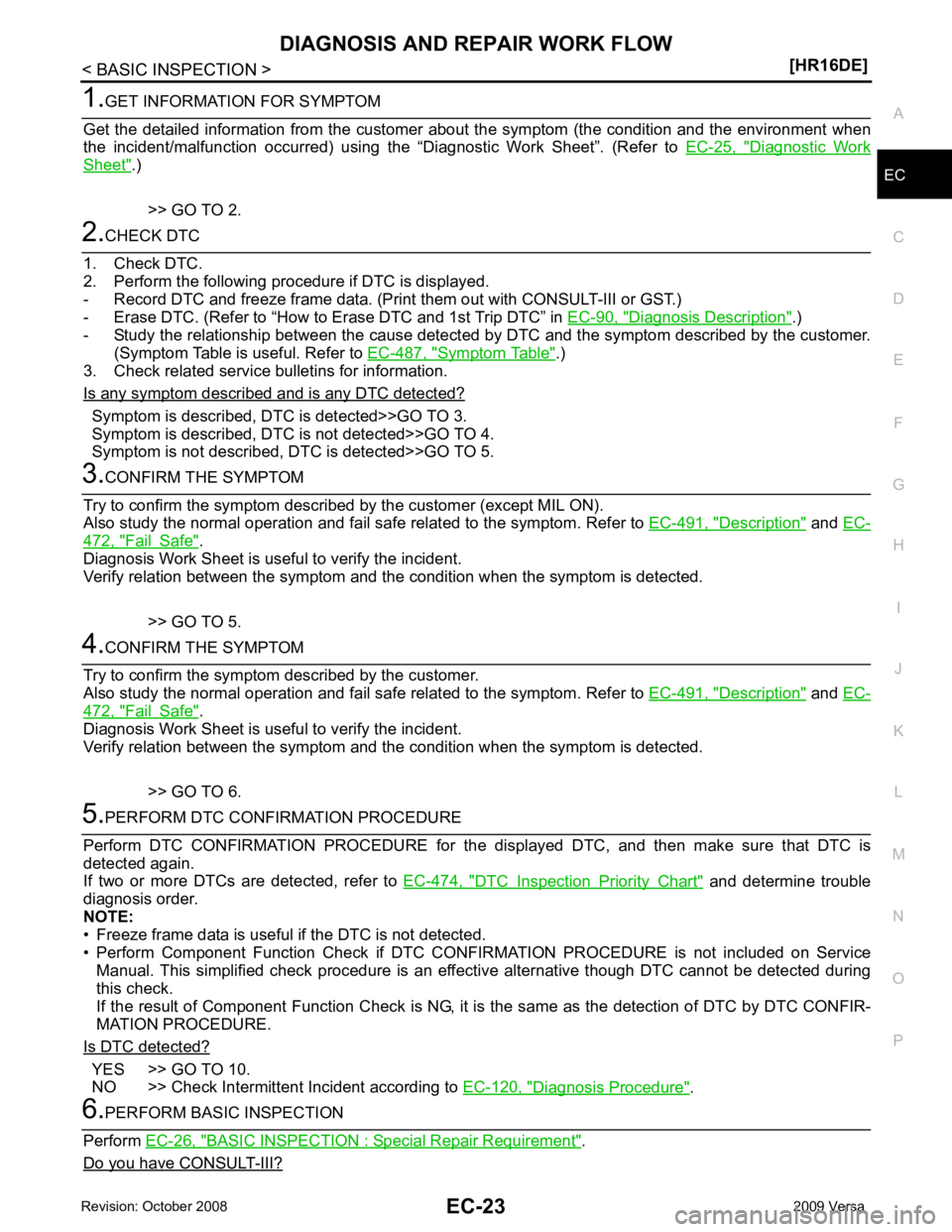
O Diagnostic Work
Sheet " .)
>> GO TO 2. Diagnosis Description " .)
- Study the relationship between the cause detected by DTC and the symptom described by the customer.
(Symptom Table is useful. Refer to EC-487, " Symptom Table " .)
3. Check related service bulletins for information.
Is any symptom described and is any DTC detected? Symptom is described, DTC is detected>>GO TO 3.
Symptom is described, DTC is not detected>>GO TO 4.
Symptom is not described, DTC is detected>>GO TO 5. Description " and
EC- 472, " Fail Safe " .
Diagnosis Work Sheet is useful to verify the incident.
Verify relation between the symptom and t he condition when the symptom is detected.
>> GO TO 5. Description " and
EC- 472, " Fail Safe " .
Diagnosis Work Sheet is useful to verify the incident.
Verify relation between the symptom and t he condition when the symptom is detected.
>> GO TO 6. DTC Inspection Priority Chart " and determine trouble
diagnosis order.
NOTE:
• Freeze frame data is useful if the DTC is not detected.
• Perform Component Function Check if DTC CONF IRMATION PROCEDURE is not included on Service
Manual. This simplified check procedure is an effect ive alternative though DTC cannot be detected during
this check.
If the result of Component Function Check is NG, it is the same as the detection of DTC by DTC CONFIR-
MATION PROCEDURE.
Is DTC detected? YES >> GO TO 10.
NO >> Check Intermittent Incident according to EC-120, " Diagnosis Procedure " .
BASIC INSPECTION : Special Repair Requirement " .
Do you have CONSULT-III?
Page 1389 of 4331

EC
NP
O
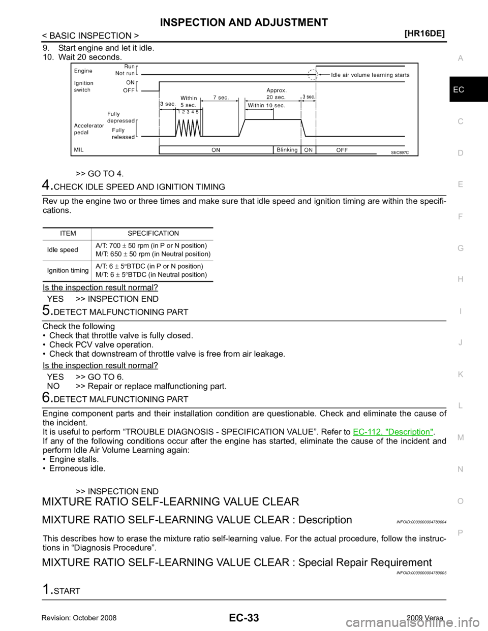
9. Start engine and let it idle.
10. Wait 20 seconds.
>> GO TO 4. YES >> INSPECTION END
YES >> GO TO 6.
NO >> Repair or replace malfunctioning part. Description " .
If any of the following conditions occur after the engi ne has started, eliminate the cause of the incident and
perform Idle Air Volume Learning again:
• Engine stalls.
• Erroneous idle.
>> INSPECTION END
MIXTURE RATIO SELF-LEARNING VALUE CLEAR
MIXTURE RATIO SELF-LEARNING VALUE CLEAR : Description INFOID:0000000004780004
This describes how to erase the mixture ratio self-lear ning value. For the actual procedure, follow the instruc-
tions in “Diagnosis Procedure”.
MIXTURE RATIO SELF-LEARNING VALUE CLEAR : Special Repair Requirement
INFOID:0000000004780005
Page 1399 of 4331

EC
NP
O
*3: ECM determines the start signal status by the signals of engine speed and battery voltage.
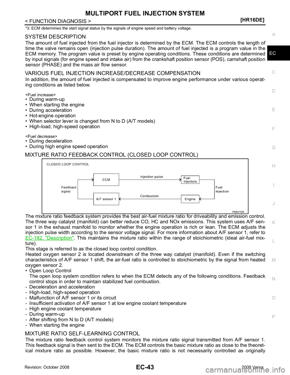
SYSTEM DESCRIPTION The amount of fuel injected from the fuel injector is determined by the ECM. The ECM controls the length of
time the valve remains open (injection pulse duration). T he amount of fuel injected is a program value in the
ECM memory. The program value is preset by engi ne operating conditions. These conditions are determined
by input signals (for engine speed and intake air) from t he crankshaft position sensor (POS), camshaft position
sensor (PHASE) and the mass air flow sensor.
VARIOUS FUEL INJECTION INCREASE/DECREASE COMPENSATION In addition, the amount of fuel injected is compens ated to improve engine performance under various operat-
ing conditions as listed below.
• During warm-up
• When starting the engine
• During acceleration
• Hot-engine operation
• When selector lever is changed from N to D (A/T models)
• High-load, high-speed operation
• During deceleration
• During high engine speed operation
MIXTURE RATIO FEEDBACK CONTROL (CLOSED LOOP CONTROL)
The mixture ratio feedback system prov ides the best air-fuel mixture ratio for driveability and emission control.
The three way catalyst (manifold) can better reduce CO, HC and NOx emissions. This system uses A/F sen-
sor 1 in the exhaust manifold to monitor whether the engine operation is rich or lean. The ECM adjusts the
injection pulse width according to the sensor voltage si gnal. For more information about A/F sensor 1, refer to
EC-182, " Description " . This maintains the mixture ratio within t
he range of stoichiometric (ideal air-fuel mix-
ture).
This stage is referred to as the closed loop control condition.
Heated oxygen sensor 2 is located downstream of the th ree way catalyst (manifold). Even if the switching
characteristics of A/F sensor 1 shift, the air-fuel rati o is controlled to stoichiometric by the signal from heated
oxygen sensor 2.
• Open Loop Control
The open loop system condition refers to when the EC M detects any of the following conditions. Feedback
control stops in order to maintain stabilized fuel combustion.
- Deceleration and acceleration
- High-load, high-speed operation
- Malfunction of A/F sensor 1 or its circuit
- Insufficient activation of A/F sensor 1 at low engine coolant temperature
- High engine coolant temperature
- During warm-up
- After shifting from N to D (A/T models)
- When starting the engine
MIXTURE RATIO SELF-LEARNING CONTROL The mixture ratio feedback control system monitors the mixture ratio signal transmitted from A/F sensor 1.
This feedback signal is then sent to the ECM. The ECM cont rols the basic mixture ratio as close to the theoret-
ical mixture ratio as possible. However, the basic mi xture ratio is not necessarily controlled as originally
Page 1407 of 4331

EC
NP
O
ELECTRIC IGNITION SYSTEM
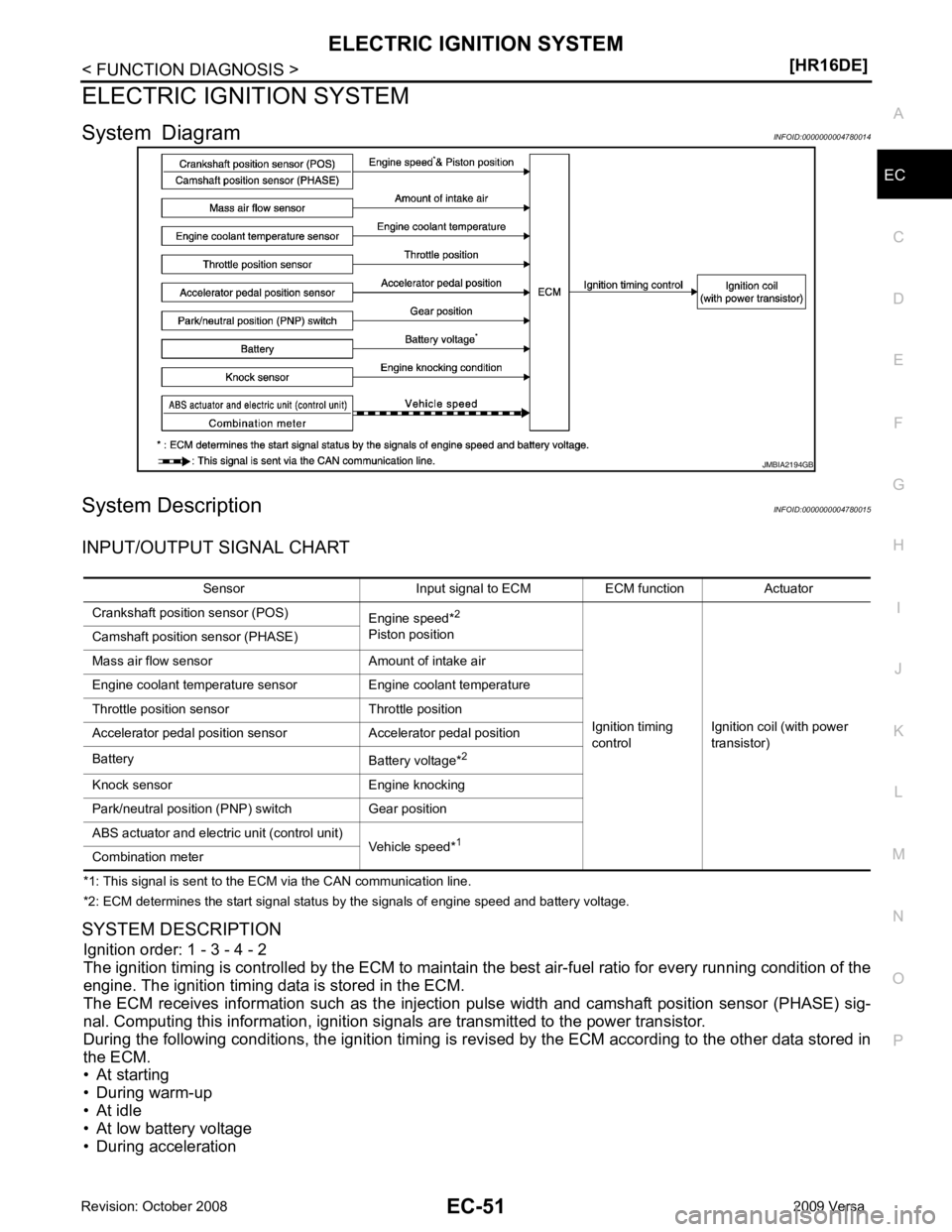
System Diagram INFOID:0000000004780014
System Description INFOID:0000000004780015
INPUT/OUTPUT SIGNAL CHART
*1: This signal is sent to the ECM via the CAN communication line.
*2: ECM determines the start signal status by the signals of engine speed and battery voltage.
SYSTEM DESCRIPTION Ignition order: 1 - 3 - 4 - 2
The ignition timing is controlled by the ECM to maintain the best air-fuel ratio for every running condition of the
engine. The ignition timing data is stored in the ECM.
The ECM receives information such as the injecti on pulse width and camshaft position sensor (PHASE) sig-
nal. Computing this information, ignition si gnals are transmitted to the power transistor.
During the following conditions, the ignition timing is revi sed by the ECM according to the other data stored in
the ECM.
• At starting
• During warm-up
• At idle
• At low battery voltage
• During acceleration