2009 NISSAN LATIO checking oil
[x] Cancel search: checking oilPage 3145 of 4331
Com-
ponent " .
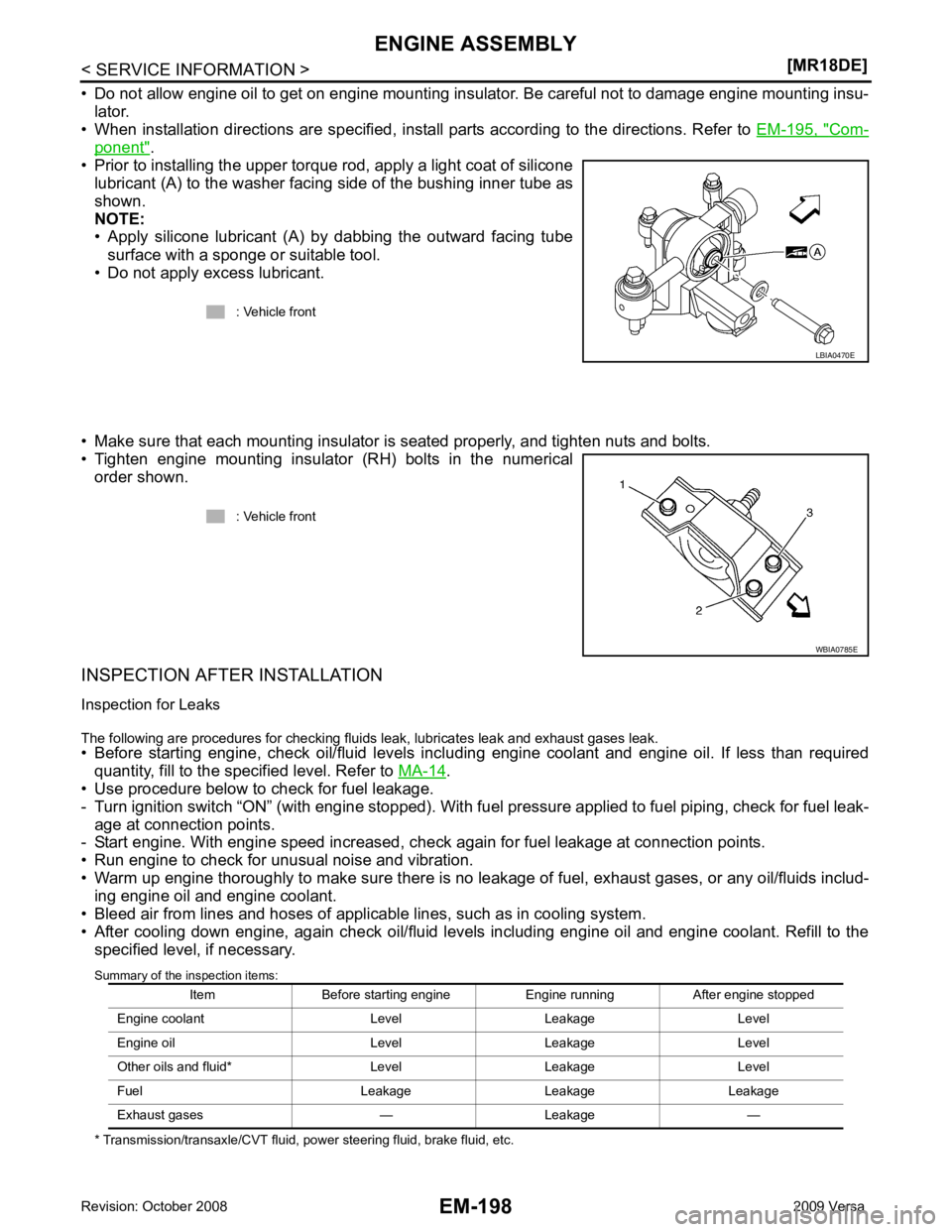
• Prior to installing the upper torque rod, apply a light coat of silicone lubricant (A) to the washer facing side of the bushing inner tube as
shown.
NOTE:
• Apply silicone lubricant (A) by dabbing the outward facing tube
surface with a sponge or suitable tool.
• Do not apply excess lubricant.
• Make sure that each mounting insulator is seated properly, and tighten nuts and bolts.
• Tighten engine mounting insulator (RH) bolts in the numerical order shown.
INSPECTION AFTER INSTALLATION
Inspection for Leaks
The following are procedures for checking fluids leak, lubricates leak and exhaust gases leak.
• Before starting engine, check oil/fluid levels incl uding engine coolant and engine oil. If less than required
quantity, fill to the specified level. Refer to MA-14 .
• Use procedure below to check for fuel leakage.
- Turn ignition switch “ON” (with engine stopped). With fuel pressure applied to fuel piping, check for fuel leak-
age at connection points.
- Start engine. With engine speed increased, che ck again for fuel leakage at connection points.
• Run engine to check for unusual noise and vibration.
• Warm up engine thoroughly to make sure there is no leak age of fuel, exhaust gases, or any oil/fluids includ-
ing engine oil and engine coolant.
• Bleed air from lines and hoses of applicable lines, such as in cooling system.
• After cooling down engine, again check oil/fluid levels including engine oil and engine coolant. Refill to the specified level, if necessary.
Summary of the inspection items:
* Transmission/transaxle/CVT fluid, power steering fluid, brake fluid, etc. : Vehicle front
Page 3254 of 4331
GI
SECTION GI
N
O P
CONTENTS
GENERAL INFORMATION
SERVICE INFORMATION .. ..........................2
PRECAUTIONS .............................................. .....2
Description .......................................................... ......2
Precaution for Supplemental Restraint System
(SRS) "AIR BAG" and "SEAT BELT PRE-TEN-
SIONER" ............................................................. ......
2
Precaution Necessary fo r Steering Wheel Rota-
tion After Battery Disconnect ............................... ......
2
General Precaution ............................................. ......3
Precaution for Three Way Catalyst ..................... ......4
Precaution for Fuel (Unleaded Regular Gasoline
Recommended) ................................................... ......
4
Precaution for Multiport Fuel Injection System or
Engine Control System ....................................... ......
5
Precaution for Hoses ........................................... ......5
Precaution for Engine Oils .................................. ......6
Precaution for Air Conditioning ........................... ......6
HOW TO USE THIS MANUAL ....................... .....7
Description .......................................................... ......7
Terms .................................................................. ......7
Units .................................................................... ......7
Contents .............................................................. ......7
Relation between Illustrations and Descriptions . ......8
Component .......................................................... ......8
How to Follow Trouble Diagnosis ........................ ......9
How to Read Wiring Diagr am ..................................13
Abbreviations ...................................................... ....20
SERVICE INFORMATION FOR ELECTRICAL
INCIDENT ....................................................... ....
22
How to Check Terminal ...........................................22 How to Perform Efficient Diagnosis for an Electri-
cal Incident .......................................................... ....
25
Control Units and Electrical Parts ........................ ....32
CONSULT-III CHECKING SYSTEM ................. 35
Description ........................................................... ....35
Function and System Application ........................ ....35
CONSULT-III Data Link Connector (DLC) Circuit ....36
LIFTING POINT ................................................. 38
Special Service Tool ............................................ ....38
Garage Jack and Safety Stand and 2-Pole Lift ... ....38
Board-On Lift ....................................................... ....39
TOW TRUCK TOWING ..................................... 40
Tow Truck Towing ............................................... ....40
Vehicle Recovery (Freeing a Stuck Vehicle) ....... ....40
TIGHTENING TORQUE OF STANDARD
BOLTS ............................................................... 41
Tightening Torque Table ..................................... ....41
RECOMMENDED CHEMICAL PRODUCTS
AND SEALANTS ............................................... 42
Recommended Chemical Product and Sealant ... ....42
IDENTIFICATION INFORMATION .................... 43
Model Variation .................................................... ....43
Dimensions .......................................................... ....46
Wheels & Tires .................................................... ....46
TERMINOLOGY ................................................ 47
SAE J1930 Terminology List ............................... ....47
Page 3257 of 4331
GI-4< SERVICE INFORMATION >
PRECAUTIONS
• Replace oil seals, gaskets, packings, O-rings, locking wa shers, cotter pins, self-locking nuts, etc. with new
ones.
• Replace inner and outer races of tapered roller bearings and needle bearings as a set.
• Arrange the disassembled parts in accordance with their assembled locations and sequence.
• Do not touch the terminals of electrical com ponents which use microcomputers (such as ECM).
Static electricity may damage internal electronic components.
• After disconnecting vacuum or air hoses, atta ch a tag to indicate the proper connection.
• Use only the fluids and lubricants specified in this manual.
• Use approved bonding agent, sealants or their equivalents when required.
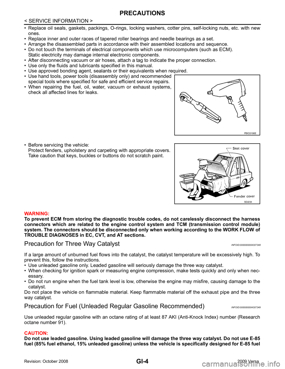
• Use hand tools, power tools (disassembly only) and recommended
special tools where specified for safe and efficient service repairs.
• When repairing the fuel, oil, water, vacuum or exhaust systems, check all affected lines for leaks.
• Before servicing the vehicle: Protect fenders, upholstery and carpeting with appropriate covers.
Take caution that keys, buckles or buttons do not scratch paint.
WARNING:
To prevent ECM from storing the diagnostic tro uble codes, do not carelessly disconnect the harness
connectors which are related to the engine cont rol system and TCM (transmission control module)
system. The connectors should be disconnected on ly when working according to the WORK FLOW of
TROUBLE DIAGNOSES in EC, CVT, and AT sections.
Precaution for Three Way Catalyst INFOID:0000000004307348
If a large amount of unburned fuel flows into the catalyst , the catalyst temperature will be excessively high. To
prevent this, follow the instructions.
• Use unleaded gasoline only. Leaded gasoline will seriously damage the three way catalyst.
• When checking for ignition spark or measuring engine compression, make tests quickly and only when nec-
essary.
• Do not run engine when the fuel tank level is low, otherwise the engine may misfire, causing damage to the
catalyst.
Do not place the vehicle on flammable material. Keep flammable material off the exhaust pipe and the three
way catalyst.
Precaution for Fuel (Unleade d Regular Gasoline Recommended) INFOID:0000000004307349
Use unleaded regular gasoline with an octane rating of at least 87 AKI (Anti-Knock Index) number (Research
octane number 91).
CAUTION:
Do not use leaded gasoline. Using leaded gasoline will damage the three way catalyst. Do not use E-85
fuel (85% fuel ethanol, 15% unl eaded gasoline) unless the vehicle is specifically designed for E-85 fuel PBIC0190E
SGI234
Page 3744 of 4331
MA
N
O P
CONTENTS
MAINTENANCE
SERVICE INFORMATION .. ..........................3
PRECAUTIONS .............................................. .....3
Precaution for Supplemental Restraint System
(SRS) "AIR BAG" and "SEAT BELT PRE-TEN-
SIONER" ............................................................. ......
3
Precaution Necessary fo r Steering Wheel Rota-
tion After Battery Disconnect ............................... ......
3
PREPARATION .............................................. .....5
Special Service Tool ........................................... ......5
Commercial Service Tool .................................... ......5
GENERAL MAINTE NANCE ........................... .....6
Explanation of General Maintenance .................. ......6
General Maintenance .......................................... ......6
PERIODIC MAINTENANCE ........................... .....9
Introduction of Periodic Maintenance .................. ......9
Schedule 1 .......................................................... ......9
Schedule 2 .......................................................... ....11
RECOMMENDED FLUIDS AND LUBRI-
CANTS ............................................................ ....
14
Fluids and Lubricants .......................................... ....14
SAE Viscosity Number ........................................ ....14
Anti-freeze Coolant Mixture Ratio ....................... ....15
ENGINE MAINTENANCE (HR16DE) ............. ....16
DRIVE BELT .......................................................... ....16
DRIVE BELT : Checking ..................................... ....16
DRIVE BELT : Tension Adjustment .................... ....16
ENGINE COOLANT ............................................... ....17
ENGINE COOLANT : Inspection ......................... ....17
ENGINE COOLANT : Changing Engine Coolant .... 17
FUEL LINES .......................................................... ....19
FUEL LINES : Checking Fuel Line ...................... ....19
AIR CLEANER FILTER ......................................... ....19 AIR CLEANER FILTER : Re
moval and Installation
....20
ENGINE OIL ........................................................... ....20
ENGINE OIL : Inspection ..................................... ....20
ENGINE OIL : Draining ........................................ ....22
ENGINE OIL : Refilling ........................................ ....22
OIL FILTER ............................................................ ....22
OIL FILTER : Removal and Installation ...................23
SPARK PLUG (HR16DE) ...................................... ....23
SPARK PLUG (HR16DE) : Exploded View ......... ....24
SPARK PLUG (HR16DE) : Removal and Installa-
tion ....................................................................... ....
24
EVAP VAPOR LINES ............................................ ....25
EVAP VAPOR LINES : Checking EVAP Vapor
Line ...................................................................... ....
25
ENGINE MAINTENANCE (MR18DE) ............... 26
DRIVE BELT .......................................................... ....26
DRIVE BELT : Component .................................. ....26
DRIVE BELT : Checking Drive Belts ................... ....26
DRIVE BELT : Tension Adjustment ..................... ....26
ENGINE COOLANT ............................................... ....26
ENGINE COOLANT : Inspection ......................... ....26
ENGINE COOLANT : Changing Engine Coolant .... 27
FUEL LINES ........................................................... ....29
FUEL LINES : Checking Fuel Line ...................... ....29
AIR CLEANER FILTER ......................................... ....29
AIR CLEANER FILTER : Component .................. ....29
AIR CLEANER FILTER : Changing Air Cleaner
Filter ..................................................................... ....
30
ENGINE OIL ........................................................... ....30
ENGINE OIL : Inspection ..................................... ....30
ENGINE OIL : Changing Engine Oil .................... ....32
OIL FILTER ............................................................ ....33
Page 3748 of 4331

PREPARATION
MA-5
< SERVICE INFORMATION >
C
D E
F
G H
I
J
K
M A
B MA
N
O P
PREPARATION
Special Service Tool INFOID:0000000004305180
The actual shapes of Kent-Moore tools may differ fr om those of special service tools illustrated here.
Commercial Service Tool INFOID:0000000004305181
Tool number
(Kent-Moore No.)
Tool name Description
KV10115801
(J-38956)
Oil filter wrench Removing and installing oil filter
a: 64.3 mm (2.531 in)
KV991J0010
(J-23688)
Engine coolant refractometer Checking concentration of ethylene glycol in
engine coolant
KV991J0070
(J-45695)
Coolant Refill Tool Refilling engine cooling system S-NT375
WBIA0539E
LMA053
(Kent-Moore No.)
Tool name Description
Power tool Loosening bolts and nuts
Spark plug wrench Removing and installing spark plug PBIC0190E
PBIC2982E
Page 3750 of 4331
MA
N
O P
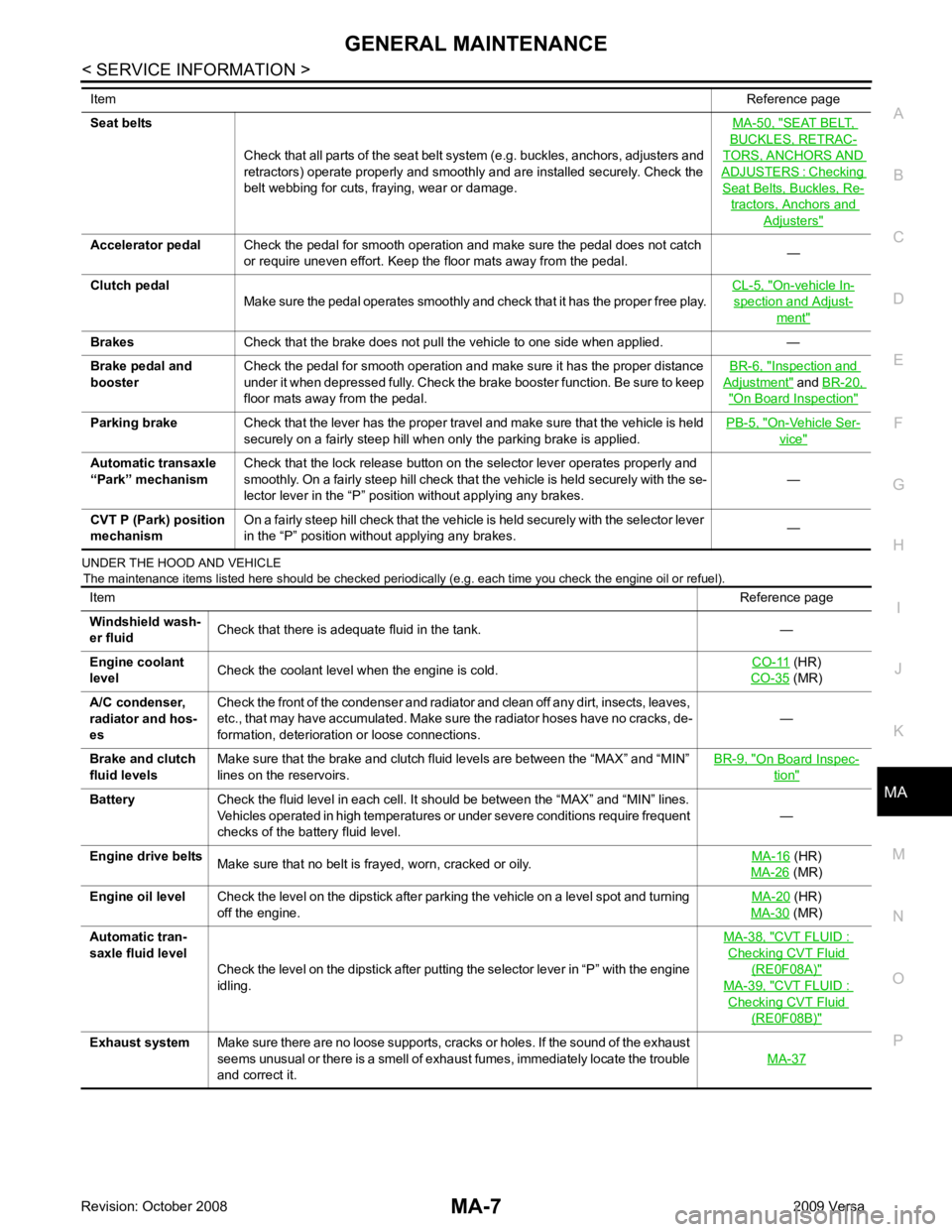
UNDER THE HOOD AND VEHICLE
The maintenance items listed here should be checked periodically (e.g. each time you check the engine oil or refuel).
Seat belts
Check that all parts of the seat belt system (e.g. buckles, anchors, adjusters and
retractors) operate properly and smoothly and are installed securely. Check the
belt webbing for cuts, fraying, wear or damage. MA-50, " SEAT BELT,
BUCKLES, RETRAC-
TORS, ANCHORS AND
ADJUSTERS : Checking
Seat Belts, Buckles, Re-
tractors, Anchors and
Adjusters "
On-vehicle In-
spection and Adjust-
ment "
Inspection and
Adjustment " and
BR-20, " On Board Inspection "
On-Vehicle Ser-
vice "
Item
Reference page
Windshield wash-
er fluid Check that there is adequate fluid in the tank. —
Engine coolant
level Check the coolant level when the engine is cold. CO-11 (HR)
CO-35 (MR)
A/C condenser,
radiator and hos-
es Check the front of the condenser and radiator and clean off any dirt, insects, leaves,
etc., that may have accumulated. Make sure the radiator hoses have no cracks, de-
formation, deterioration or loose connections. —
Brake and clutch
fluid levels Make sure that the brake and clutch fluid levels are between the “MAX” and “MIN”
lines on the reservoirs. BR-9, " On Board Inspec-
tion "
(HR)
MA-26 (MR)
Engine oil level Check the level on the dipstick after parking the vehicle on a level spot and turning
off the engine. MA-20 (HR)
MA-30 (MR)
Automatic tran-
saxle fluid level Check the level on the dipstick after putting the selector lever in “P” with the engine
idling. MA-38, " CVT FLUID :
Checking CVT Fluid
(RE0F08A) "
MA-39, " CVT FLUID :
Checking CVT Fluid
(RE0F08B) "
Page 3759 of 4331
MA-16< SERVICE INFORMATION >
ENGINE MAINTENANCE (HR16DE)
ENGINE MAINTENANCE (HR16DE)
DRIVE BELT
DRIVE BELT : Checking INFOID:0000000004806005
• Inspection should be done only when engine is cold or over 30 minutes after the engine is stopped.
• Visually check belts for wear, damage, and cracks on inside and edges.
• Turn crankshaft pulley two time clockwise, and make sure tension on all pulleys is equal before doing the test.
• When measuring deflection, apply 98 N (10 kg, 22 lb) at the ( ) marked point.
• Measure the belt tension and frequency with acous tic tension gauge at the ( ) marked point.
CAUTION:
• When the tension and frequency are measured, the acoustic tension gauge should be used.
• When checking immediately after installation, first ad just it to the specified value. Then, after turning
crankshaft two turns or more, re-adjust to the sp ecified value to avoid variation in deflection
between pulleys.
DRIVE BELT : Tension Adjustment INFOID:0000000004806006
CAUTION:
• When belt is replaced with new one, adjust belt tension to the value for “New belt”, because new belt
will not fully seat in the pulley groove.
• When tension of the belt being used exceeds “Limit”, adjust it to the value for “After adjusted”.
• When installing a belt, make sure it is correctly engaged with the pulley groove.
• Never allow oil or engine coolant to get on the belt.
• Never twist or bend the belt strongly.
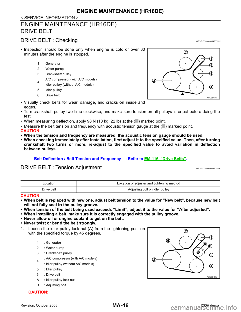
1. Loosen the idler pulley lock nut (A) from the tightening position with the specified torque by 45 degrees.
CAUTION: 1 : Generator
2 : Water pump
3 : Crankshaft pulley
4 : A/C compressor (with A/C models)
: Idler pulley (without A/C models)
5 : Idler pulley
6 : Drive belt
Belt Deflection / Belt Tension and Frequency : Refer to EM-116, " Drive Belts " . PBIC3642E
Location Location of adjuster and tightening method
Drive belt Adjusting bolt on idler pulley
1 : Generator
2 : Water pump
3 : Crankshaft pulley
4 : A/C compressor
(with A/C models)
: Idler pulley (without A/C models)
5 : Idler pulley
6 : Drive belt
A : Idler pulley lock nut
B : Adjusting bolt PBIC3643E
Page 3779 of 4331

MA-36< SERVICE INFORMATION >
ENGINE MAINTENANCE (MR18DE)
2. Install rocker cover. • Tighten bolts in two steps separately in numerical order asshown.
• Engine front
CAUTION:
Check if rocker cover gasket is not dropped from the instal-
lation groove of rocker cover.
3. Install spark plug using suitable tool.
CAUTION:
Never drop or shock it.
4. Install ignition coil. CAUTION:
• Handle it carefully and avoid impacts.
• Never disassemble.
5. Install intake manifold. Refer to EM-141 .
EVAP VAPOR LINES
EVAP VAPOR LINES : Checking EVAP Vapor Line INFOID:0000000004305200
1. Visually inspect EVAP vapor lines for improper attachment and for cracks, damage, loose connections,
chafing and deterioration.
2. Inspect fuel tank filler cap vacuum relief valve for clogging, sticking, etc. Refer to EC-529, " Component Inspection " .
1st step : 1.96 N·m (0.20 kg-m, 17 in-lb)
2nd step : 8.33 N·m (0.85 kg-m, 73 in-lb) PBIC3151J
Make : DENSO
Part number : FXE20HR11
Gap (nominal) : 1.1 mm (0.043 in) PBIC3871E