2009 NISSAN LATIO checking oil
[x] Cancel search: checking oilPage 3936 of 4331
MTC
N
O P
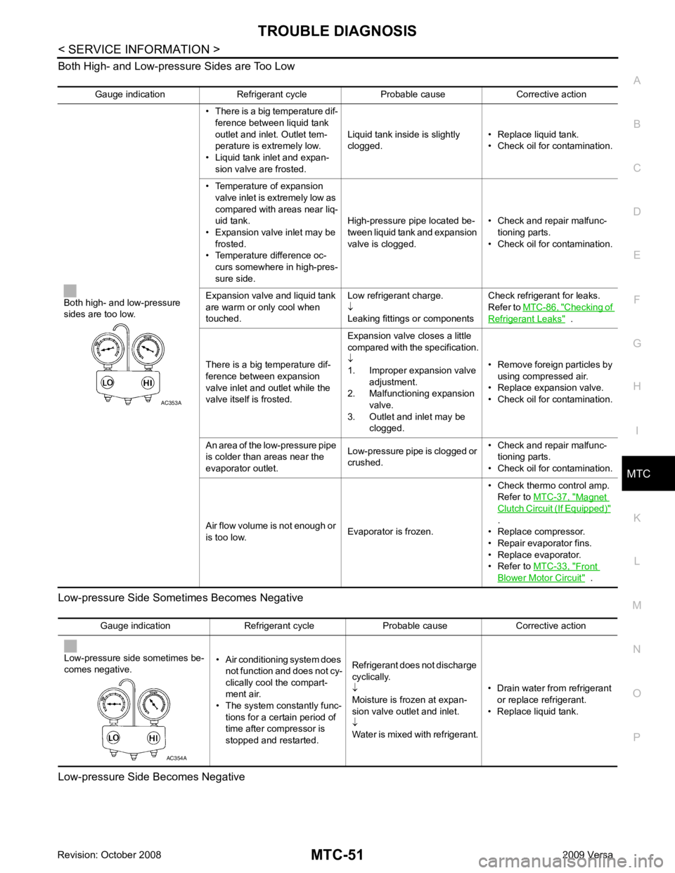
Both High- and Low-pressure Sides are Too Low
Low-pressure Side Some times Becomes Negative
Low-pressure Side Becomes Negative Gauge indication Refrigerant cycle Probable cause Corrective action
Both high- and low-pressure
sides are too low. • There is a big temperature dif-
ference between liquid tank
outlet and inlet. Outlet tem-
perature is extremely low.
• Liquid tank inlet and expan- sion valve are frosted. Liquid tank inside is slightly
clogged. • Replace liquid tank.
• Check oil for contamination.
• Temperature of expansion valve inlet is extremely low as
compared with areas near liq-
uid tank.
• Expansion valve inlet may be
frosted.
• Temperature difference oc- curs somewhere in high-pres-
sure side. High-pressure pipe located be-
tween liquid tank and expansion
valve is clogged. • Check and repair malfunc-
tioning parts.
• Check oil for contamination.
Expansion valve and liquid tank
are warm or only cool when
touched. Low refrigerant charge.
↓
Leaking fittings or components Check refrigerant for leaks.
Refer to MTC-86, " Checking of
Refrigerant Leaks " .
There is a big temperature dif-
ference between expansion
valve inlet and outlet while the
valve itself is frosted. Expansion valve closes a little
compared with the specification.
↓
1. Improper expansion valve
adjustment.
2. Malfunctioning expansion valve.
3. Outlet and inlet may be clogged. • Remove foreign particles by
using compressed air.
• Replace expansion valve.
• Check oil for contamination.
An area of the low-pressure pipe
is colder than areas near the
evaporator outlet. Low-pressure pipe is clogged or
crushed. • Check and repair malfunc-
tioning parts.
• Check oil for contamination.
Air flow volume is not enough or
is too low. Evaporator is frozen.• Check thermo control amp.
Refer to MTC-37, " Magnet
Clutch Circuit (If Equipped) "
.
• Replace compressor.
• Repair evaporator fins.
• Replace evaporator.
• Refer to MTC-33, " Front
Blower Motor Circuit " .
Page 3939 of 4331

Operational Check " *2.
EM-14, " Checking " (HR16DE) or
EM- 136, " Checking Drive Belts "
(MR18DE) *3.
MTC-45, " Insufficient Cooling "
*4.
MTC-86, " Removal and Installation of
Expansion Valve " *5.
MTC-78, " Removal and Installation of
Compressor - HR16DE " or
MTC-80, " Removal and Installation of Com-
pressor - MR18DE " *6
MTC-78, " Removal and Installation of
Compressor - HR16DE " or
MTC-80, " Removal and Installation of Com-
pressor - MR18DE "
*7.
MTC-78, " Removal and Installation of
Compressor - HR16DE " or
MTC-80, " Removal and Installation of Com-
pressor - MR18DE " *8.
MTC-17, " Maintenance of Oil Quanti-
ty in Compressor " *9
MTC-84, " Removal and Installation of
Liquid Tank "
Page 3960 of 4331

MTC
N
O P
7. Manifold gauge set (J-39183) A. Prefe
rred (best) method B. Alternative method
C. For charging
*1 MTC-17, " Maintenance of Oil Quanti-
ty in Compressor " *2
MTC-86, " Checking of Refrigerant
Leaks " *3
MTC-87, " Electronic Refrigerant
Leak Detector "
*4
MTC-45, " Insufficient Cooling "
Page 3964 of 4331
MTC
N
O P
1. Use the recovery/recycling equipment
to evacuate the refrigerant. Refer to MTC-74, " HFC-134a (R-134a)
Service Procedure " .
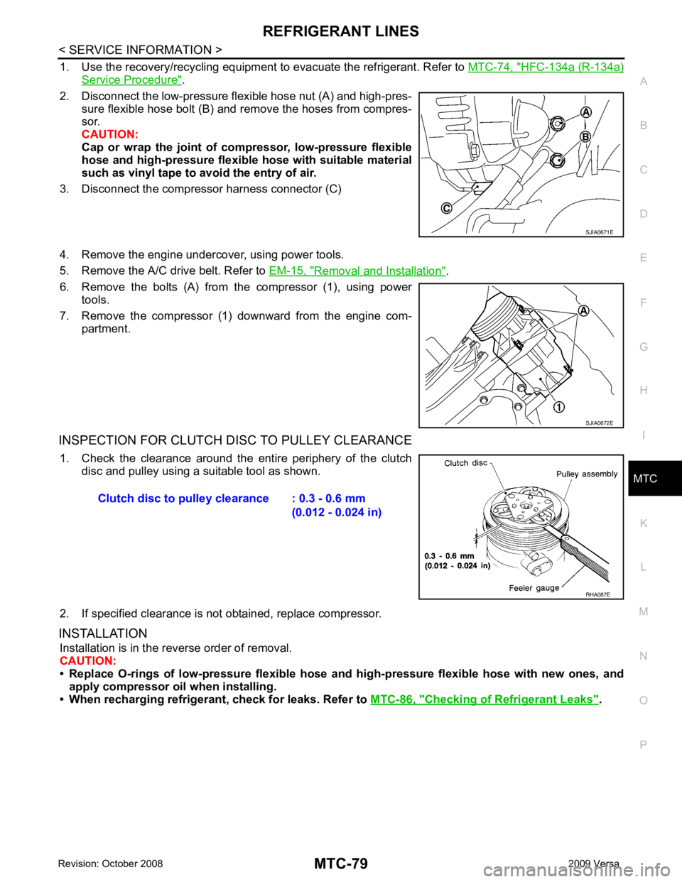
2. Disconnect the low-pressure flexible hose nut (A) and high-pres- sure flexible hose bolt (B) and remove the hoses from compres-
sor.
CAUTION:
Cap or wrap the joint of co mpressor, low-pressure flexible
hose and high-pressure flexible hose with suitable material
such as vinyl tape to avoid the entry of air.
3. Disconnect the compressor harness connector (C)
4. Remove the engine undercover, using power tools.
5. Remove the A/C drive belt. Refer to EM-15, " Removal and Installation " .
6. Remove the bolts (A) from the compressor (1), using power tools.
7. Remove the compressor (1) downward from the engine com- partment.
INSPECTION FOR CLUTCH DISC TO PULLEY CLEARANCE 1. Check the clearance around the entire periphery of the clutch disc and pulley using a suitable tool as shown.
2. If specified clearance is not obtained, replace compressor.
INSTALLATION Installation is in the reverse order of removal.
CAUTION:
• Replace O-rings of low-pressure flexible hose and high-pressure flexible hose with new ones, and
apply compressor oil when installing.
• When recharging refrigeran t, check for leaks. Refer to MTC-86, " Checking of Refrigerant Leaks " .
Page 3966 of 4331
MTC
N
O P
INSPECTION FOR CLUTCH DISC TO PULLEY CLEARANCE
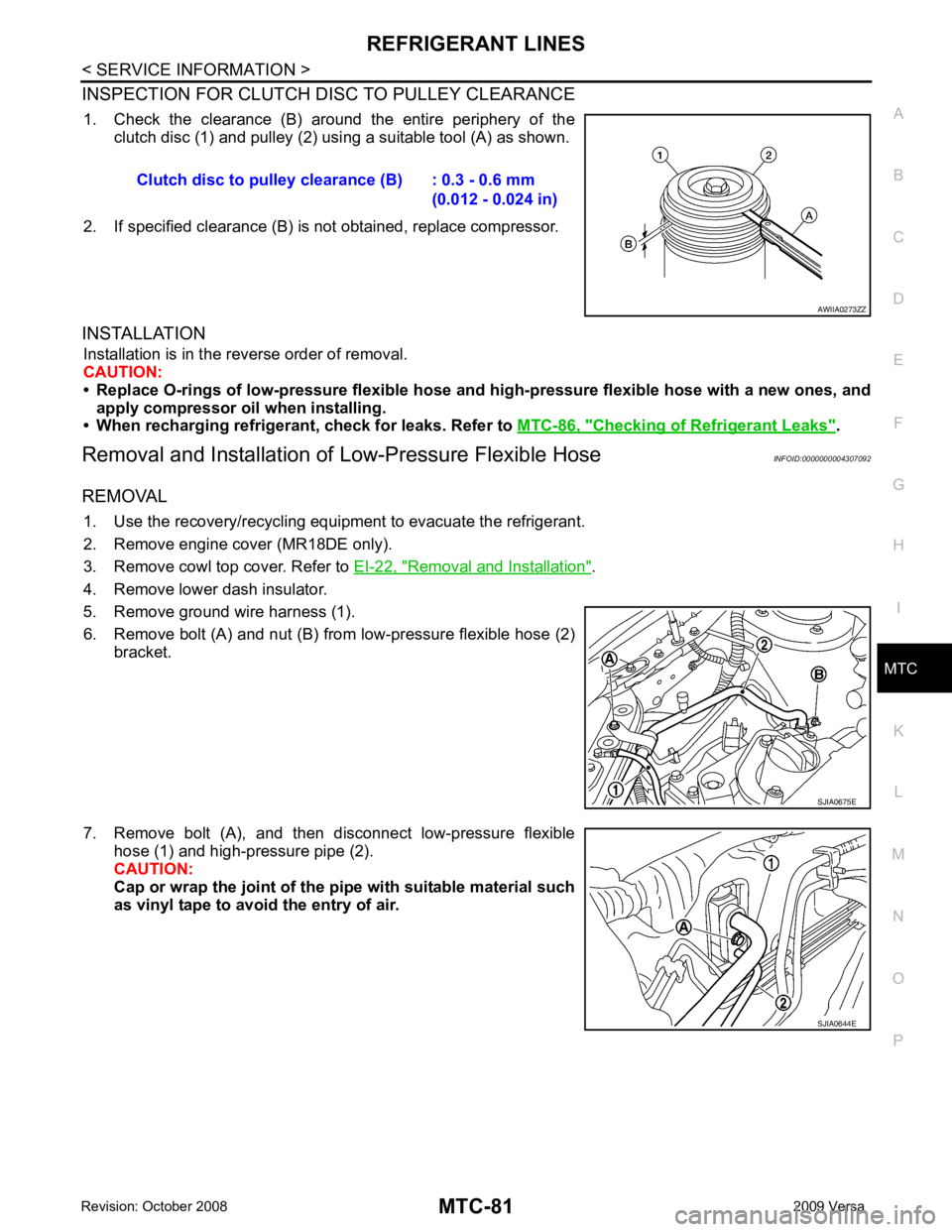
1. Check the clearance (B) around the entire periphery of the clutch disc (1) and pulley (2) usi ng a suitable tool (A) as shown.
2. If specified clearance (B) is not obtained, replace compressor.
INSTALLATION Installation is in the reverse order of removal.
CAUTION:
• Replace O-rings of low-pressure flexible hose and high-pressure flexible hose with a new ones, and
apply compressor oil when installing.
• When recharging refrigeran t, check for leaks. Refer to MTC-86, " Checking of Refrigerant Leaks " .
Removal and Installation of Low-Pressure Flexible Hose INFOID:0000000004307092
REMOVAL 1. Use the recovery/recycling equipment to evacuate the refrigerant.
2. Remove engine cover (MR18DE only).
3. Remove cowl top cover. Refer to EI-22, " Removal and Installation " .
4. Remove lower dash insulator.
5. Remove ground wire harness (1).
6. Remove bolt (A) and nut (B) from low-pressure flexible hose (2) bracket.
7. Remove bolt (A), and then disconnect low-pressure flexible hose (1) and high-pressure pipe (2).
CAUTION:
Cap or wrap the joint of the pi pe with suitable material such
as vinyl tape to avoid the entry of air. Clutch disc to pulley clearance (B) : 0.3 - 0.6 mm
(0.012 - 0.024 in)
Page 3970 of 4331
MTC
N
O P
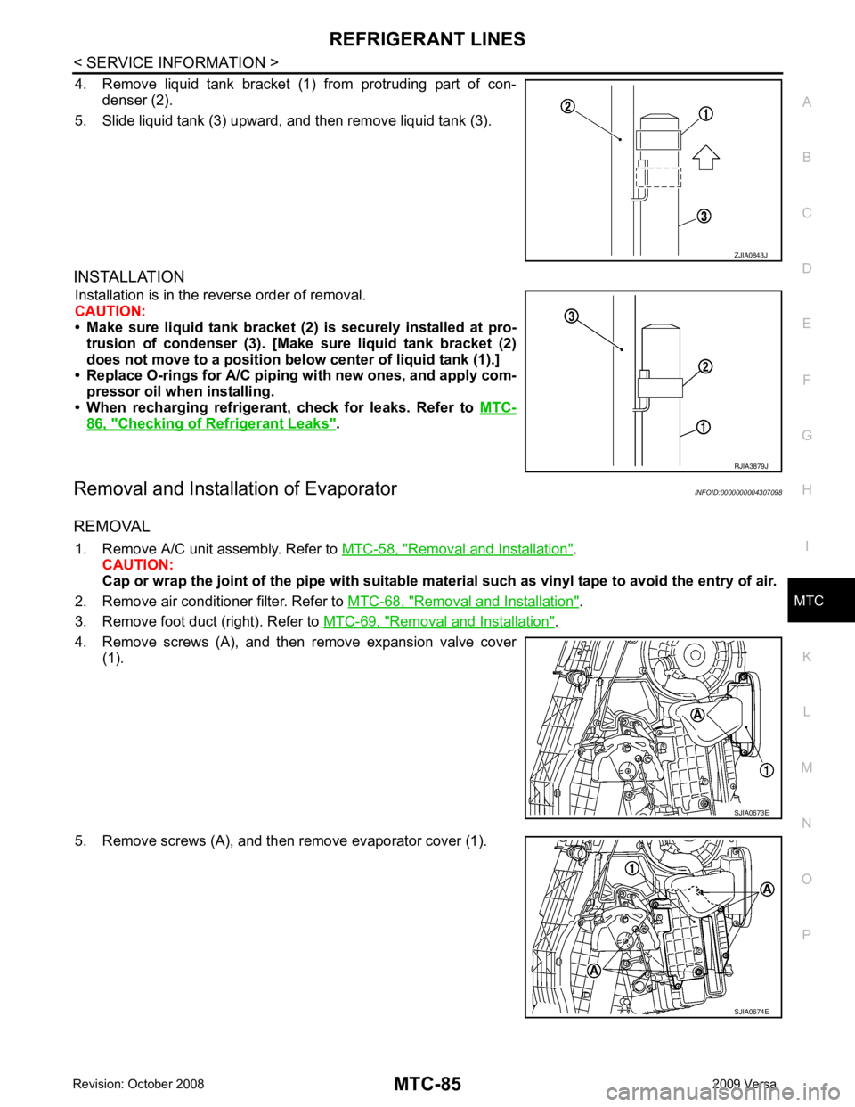
4. Remove liquid tank bracket (1
) from protruding part of con-
denser (2).
5. Slide liquid tank (3) upward, and then remove liquid tank (3).
INSTALLATION Installation is in the reverse order of removal.
CAUTION:
• Make sure liquid tank bracket (2) is securely installed at pro-
trusion of condenser (3). [Make sure liquid tank bracket (2)
does not move to a position belo w center of liquid tank (1).]
• Replace O-rings for A/C piping with new ones, and apply com-
pressor oil when installing.
• When recharging refrigerant, check for leaks. Refer to MTC-86, " Checking of Refrigerant Leaks " .
Removal and Installation of Evaporator INFOID:0000000004307098
REMOVAL 1. Remove A/C unit assembly. Refer to MTC-58, " Removal and Installation " .
CAUTION:
Cap or wrap the joint of the pipe with suitable ma terial such as vinyl tape to avoid the entry of air.
2. Remove air conditioner filter. Refer to MTC-68, " Removal and Installation " .
3. Remove foot duct (right). Refer to MTC-69, " Removal and Installation " .
4. Remove screws (A), and then remove expansion valve cover (1).
5. Remove screws (A), and then remove evaporator cover (1). RJIA3879J
Page 3971 of 4331

Removal and Installation " .
3. Remove lower dash insulator.
4. Disconnect low-pressure flexible hose and high-pressure pipe from evaporator. Refer to MTC-58," Removal and Installation " .
5. Remove expansion valve bolts (A), and then remove expansion valve (1).
CAUTION:
Cap or wrap the joint of the pi pe with suitable material such
as vinyl tape to avoid the entry of air.
INSTALLATION
Installation is in the reverse order of removal.
CAUTION:
• Replace O-rings of evaporator with new ones, and apply compressor oil when installing.
• When recharging refrigerant, check for leaks.
Checking of Refrigerant Leaks INFOID:0000000004307100
Perform a visual inspection of all refrigeration parts, fittings, hoses and components for signs of A/C oil leak-
age, damage and corrosion. A/C oil leakage may indicate an area of refrigerant leakage. Allow extra inspec-
tion time in these areas when using either an electroni c refrigerant leak detector or fluorescent dye leak
detector.
If dye is observed, confirm the leak with an electronic refrigerant leak detector. It is possible a prior leak was
repaired and not properly cleaned.
When searching for leaks, do not stop when one leak is found but continue to check for additional leaks at all
system components and connections.
When searching for refrigerant leaks using an electroni c leak detector, move the probe along the suspected
leak area at 25 to 50 mm (1 to 2 in) per sec ond and no further than 1/4 inch from the component.
CAUTION:
Page 3972 of 4331
REFRIGERANT LINES
MTC-87
< SERVICE INFORMATION >
C
D E
F
G H
I
K L
M A
B MTC
N
O P
Moving the electronic leak detector probe slower
and closer to the suspected leak area will improve
the chances of finding a leak.
Checking System for Leaks Using the Fluorescent Leak Detector INFOID:0000000004307101
1. Check A/C system for leaks using the UV lamp and safety goggles J-42220 in a low sunlight area (area
without windows preferable). Illuminate all components, fittings and lines. The dye will appear as a bright
green/yellow area at the point of leakage. Fluoresc ent dye observed at the evaporator drain opening indi-
cates an evaporator core assembly (tubes , core or expansion valve) leak.
2. If the suspected area is difficult to see, use an adjustable mirror or wipe the area with a clean shop rag or
cloth, with the UV lamp for dye residue.
3. After the leak is repaired, remove any residual dye using dye cleaner J-43872 to prevent future misdiag- nosis.
4. Perform a system performance check and verify the leak repair with an approved electronic refrigerant leak detector.
NOTE:
Other gases in the work area or substances on the A/C components, for example, anti-freeze, windshield
washer fluid, solvents and oils, may falsely trigger the l eak detector. Make sure the surfaces to be checked are
clean.
Clean with a dry cloth or blow off with shop air.
Do not allow the sensor tip of the detector to contact with any substance. This can also cause false readings
and may damage the detector.
Dye Injection INFOID:0000000004307102
(This procedure is only necessary when recharging t he system or when the compressor has seized and was
replaced.)
1. Check A/C system static (at rest) pressure. Pres sure must be at least 345 kPa (3.45 bar, 3.52 kg/cm2
, 50
psi).
2. Pour one bottle (1/4 ounce / 7.4 cc) of the A/C refrigerant dye into the injector tool J-41459.
3. Connect the injector tool to the A/C low-pressure side service fitting.
4. Start engine and switch A/C ON.
5. When the A/C operating (compressor running), inject one bottle (1/4 ounce / 7.4 cc) of fluorescent dye
through the low-pressure service valve using dye inje ctor tool J-41459 (refer to the manufacture’s operat-
ing instructions).
6. With the engine still running, disconnect the injector tool from the service fitting.
CAUTION:
Be careful the A/C system or replacing a componen t, pour the dye directly into the open system
connection and proceed wi th the service procedures.
7. Operate the A/C system for a minimum of 20 minutes to mix the dye with the system oil. Depending on the
leak size, operating conditions and location of the leak , it may take from minutes to days for the dye to
penetrate a leak and become visible.
Electronic Refrigerant Leak Detector INFOID:0000000004307103
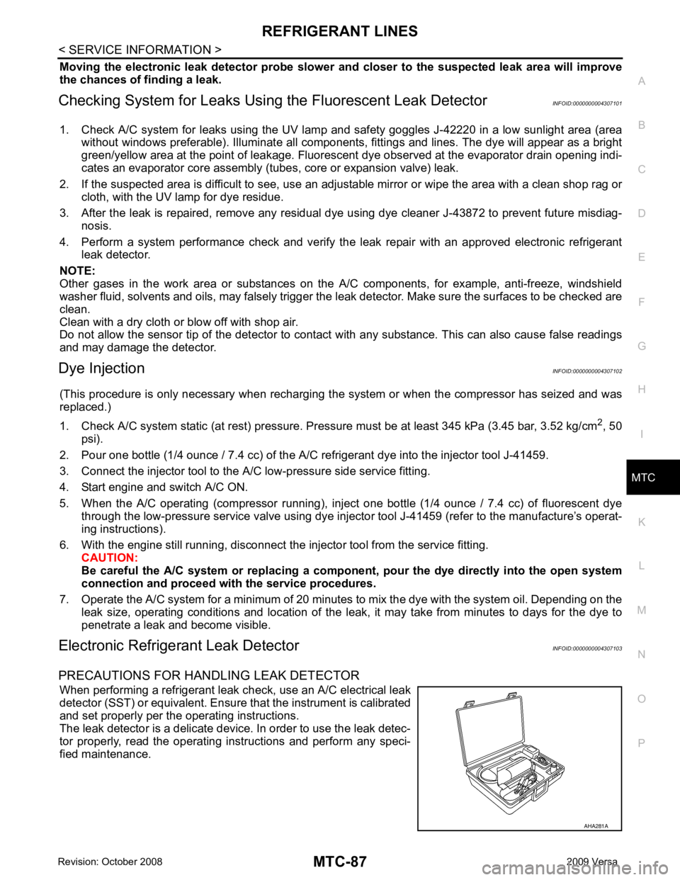
PRECAUTIONS FOR HANDLING LEAK DETECTOR When performing a refrigerant leak c heck, use an A/C electrical leak
detector (SST) or equivalent. Ensure that the instrument is calibrated
and set properly per the operating instructions.
The leak detector is a delicate device. In order to use the leak detec-
tor properly, read the operating instructions and perform any speci-
fied maintenance. AHA281A