2009 NISSAN LATIO checking oil
[x] Cancel search: checking oilPage 3786 of 4331
MA
N
O P
M/T OIL : Refilling (RS5F91R)
INFOID:0000000004803422
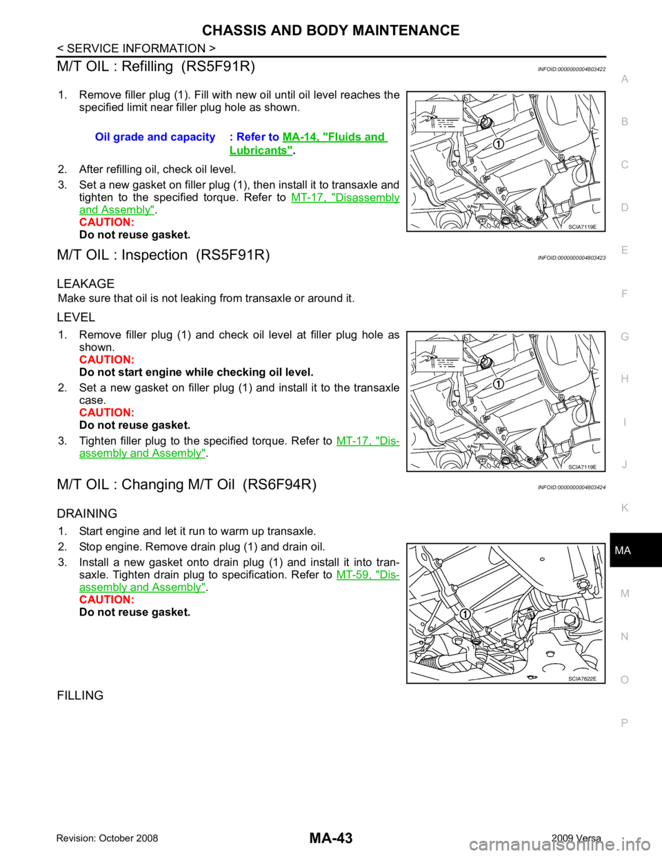
1. Remove filler plug (1). Fill with new oil until oil level reaches the specified limit near filler plug hole as shown.
2. After refilling oil, check oil level.
3. Set a new gasket on filler plug (1), then install it to transaxle and tighten to the specified torque. Refer to MT-17, " Disassembly
and Assembly " .
CAUTION:
Do not reuse gasket.
M/T OIL : Inspection (RS5F91R) INFOID:0000000004803423
LEAKAGE Make sure that oil is not leaking from transaxle or around it.
LEVEL 1. Remove filler plug (1) and check oil level at filler plug hole as shown.
CAUTION:
Do not start engine while checking oil level.
2. Set a new gasket on filler plug (1) and install it to the transaxle case.
CAUTION:
Do not reuse gasket.
3. Tighten filler plug to the specified torque. Refer to MT-17, " Dis-
assembly and Assembly " .
M/T OIL : Changing M/T Oil (RS6F94R) INFOID:0000000004803424
DRAINING 1. Start engine and let it run to warm up transaxle.
2. Stop engine. Remove drain plug (1) and drain oil.
3. Install a new gasket onto drain plug (1) and install it into tran- saxle. Tighten drain plug to specification. Refer to MT-59, " Dis-
assembly and Assembly " .
CAUTION:
Do not reuse gasket.
FILLING Oil grade and capacity : Refer to
MA-14, " Fluids and
Lubricants " .
SCIA7622E
Page 3787 of 4331
Disassembly and Assembly " .
CAUTION:
Do not reuse gasket.
M/T OIL : Checking M/T Oil (RS6F94R) INFOID:0000000004803425
OIL LEAKAGE AND OIL LEVEL
1. Make sure that oil is not leaking from transaxle or around it.
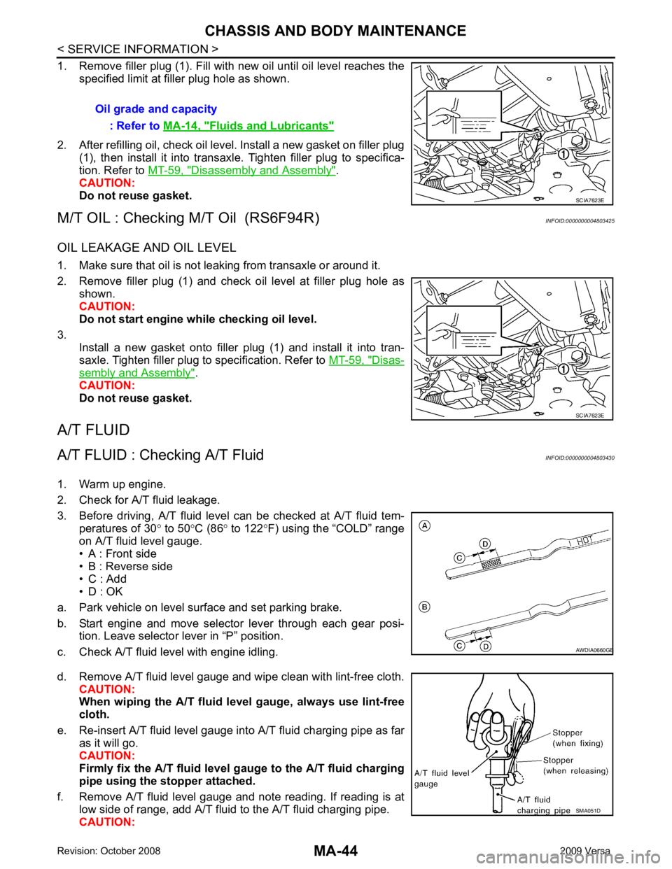
2. Remove filler plug (1) and check oil level at filler plug hole as shown.
CAUTION:
Do not start engine wh ile checking oil level.
3. Install a new gasket onto filler plug (1) and install it into tran-
saxle. Tighten filler plug to specification. Refer to MT-59, " Disas-
sembly and Assembly " .
CAUTION:
Do not reuse gasket.
A/T FLUID
A/T FLUID : Checking A/T Fluid INFOID:0000000004803430
1. Warm up engine.
2. Check for A/T fluid leakage.
3. Before driving, A/T fluid level can be checked at A/T fluid tem- peratures of 30 ° to 50 °C (86 ° to 122 °F) using the “COLD” range
on A/T fluid level gauge.
• A : Front side
• B : Reverse side
• C : Add
• D : OK
a. Park vehicle on level surface and set parking brake.
b. Start engine and move selector lever through each gear posi- tion. Leave selector lever in “P” position.
c. Check A/T fluid level with engine idling.
d. Remove A/T fluid level gauge and wipe clean with lint-free cloth. CAUTION:
When wiping the A/T fluid level gauge, always use lint-free
cloth.
e. Re-insert A/T fluid level gauge into A/T fluid charging pipe as far as it will go.
CAUTION:
Firmly fix the A/T fluid level ga uge to the A/T fluid charging
pipe using the stopper attached.
f. Remove A/T fluid level gauge and note reading. If reading is at low side of range, add A/T fluid to the A/T fluid charging pipe.
CAUTION: Oil grade and capacity
: Refer to MA-14, " Fluids and Lubricants "
SCIA7623E
B
Page 3795 of 4331
MT
N
O P
CONTENTS
MANUAL TRANSAXLE
RS5F91R
SERVICE INFORMATION .. ..........................
3
PRECAUTIONS .............................................. .....3
Precaution for Supplemental Restraint System
(SRS) "AIR BAG" and "SEAT BELT PRE-TEN-
SIONER" ............................................................. ......
3
PREPARATION .............................................. .....4
Special Service Tools ........................................ ......4
Commercial Service Tools ................................. ......5
NOISE, VIBRATION AND HARSHNESS
(NVH) TROUBLESHOOTING ........................ .....
7
NVH Troubleshooting Chart ................................ ......7
DESCRIPTION ............................................... .....8
System Diagram .................................................. ......8
System Description ............................................. ......8
M/T OIL ........................................................... ....10
Draining ............................................................... ....10
Refilling ............................................................... ....10
Inspection ............................................................ ....10
SIDE OIL SEAL .............................................. ....11
Removal and Installation .........................................11
POSITION SWITCH ........................................ ....12
Checking ............................................................. ....12
CONTROL LINKAGE ..................................... ....13
Exploded View .................................................... ....13
Removal and Installation .........................................13
Inspection ............................................................ ....14
AIR BREATHER HOSE .................................. ....15
Exploded View .................................................... ....15
Removal and Installation .........................................15
TRANSAXLE ASSEMBLY ............................. ....16
Exploded View .................................................... ....16 Removal and Installation .....................................
....16
Disassembly and Assembly ................................. ....17
INPUT SHAFT AND GEAR ............................... 36
Disassembly and Assembly ................................. ....36
MAINSHAFT AND GEAR ................................. 37
Disassembly and Assembly ................................. ....37
FINAL DRIVE .................................................... 41
Disassembly and Assembly ................................. ....41
SHIFT CONTROL .............................................. 42
Inspection ............................................................ ....42
SERVICE DATA AND SPECIFICATIONS
(SDS) ................................................................. 43
General Specification .......................................... ....43
RS6F94R
SERVICE INFORMATION .. .........................44
PRECAUTIONS ................................................. 44
Precaution for Supplemental Restraint System
(SRS) "AIR BAG" and "SEAT BELT PRE-TEN-
SIONER" ............................................................. ....
44
Precaution for Procedure without Cowl Top Cover ....44
Precaution ........................................................... ....44
PREPARATION ................................................. 45
Special Service Tool ............................................ ....45
Commercial Service Tool .................................... ....47
NOISE, VIBRATION AND HARSHNESS
(NVH) TROUBLESHOOTING ........................... 49
NVH Troubleshooting Chart ................................ ....49
DESCRIPTION .................................................. 50
Cross-Sectional View ...... ........................................50
M/T OIL .............................................................. 52
Changing M/T Oil ................................................. ....52
Checking M/T Oil ................................................. ....52
Page 3804 of 4331

MT-10< SERVICE INFORMATION >
[RS5F91R]
M/T OIL
M/T OIL
Draining INFOID:0000000004784220
1. Start engine and let it run to warm up transaxle.
2. Stop engine. Remove drain plug (1) and drain oil.
3. Set a new gasket on drain plug (1) and install it to transaxle and tighten drain plug to the specified torque. Refer to MT-17, " Dis-
assembly and Assembly " .
CAUTION:
Do not reuse gasket.
Refilling INFOID:0000000004784221
1. Remove filler plug (1). Fill with new oil until oil level reaches the specified limit near filler plug hole as shown.
2. After refilling oil, check oil level.
3. Set a new gasket on filler plug (1), then install it to transaxle and tighten to the specified torque. Refer to MT-17, " Disassembly
and Assembly " .
CAUTION:
Do not reuse gasket.
Inspection INFOID:0000000004784222
LEAKAGE
Make sure that oil is not leaking from transaxle or around it.
LEVEL
1. Remove filler plug (1) and check oil level at filler plug hole as shown.
CAUTION:
Do not start engine wh ile checking oil level.
2. Set a new gasket on filler plug (1) and install it to the transaxle case.
CAUTION:
Do not reuse gasket.
3. Tighten filler plug to the specified torque. Refer to MT-17, " Dis-
assembly and Assembly " . PCIB1504E
Oil grade and capacity : Refer to
MA-14, " Fluids and
Lubricants " .
SCIA7119E
SCIA7119E
Page 3846 of 4331
Dis-
assembly and Assembly " .
CAUTION:
Do not reuse gasket.
FILLING
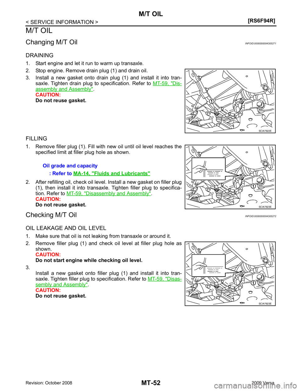
1. Remove filler plug (1). Fill with new oil until oil level reaches the specified limit at filler plug hole as shown.
2. After refilling oil, check oil level. Install a new gasket on filler plug (1), then install it into transaxle. Tighten filler plug to specifica-
tion. Refer to MT-59, " Disassembly and Assembly " .
CAUTION:
Do not reuse gasket.
Checking M/T Oil INFOID:0000000004305272
OIL LEAKAGE AND OIL LEVEL
1. Make sure that oil is not leaking from transaxle or around it.
2. Remove filler plug (1) and check oil level at filler plug hole as shown.
CAUTION:
Do not start engine wh ile checking oil level.
3. Install a new gasket onto filler plug (1) and install it into tran-
saxle. Tighten filler plug to specification. Refer to MT-59, " Disas-
sembly and Assembly " .
CAUTION:
Do not reuse gasket. Fluids and Lubricants "
Page 3847 of 4331

MT
N
O P
SIDE OIL SEAL
Removal and Installation INFOID:0000000004305273
REMOVAL 1. Remove front drive shafts from transaxle assembly. Refer to FAX-9, " Removal and Installation (Left
Side) " .
2. Remove differential side oil seal (1) using a suitable tool.
CAUTION:
Be careful not to damage transaxle case and clutch housing.
INSTALLATION Installation is in the reverse order of removal.
• Install differential side oil seals (1) to clutch housing and transaxle case using Tool (A).
• B: Transaxle case side
• C: Clutch housing side
CAUTION:
• Never reuse differential side oil seal.
• When installing, never inclin e differential side oil seal.
• Never damage clutch housing and transaxle case.
Check oil level and oil leakage after installation. Refer to MT-52," Checking M/T Oil " .
Page 3853 of 4331
MT
N
O P
Installation is in the reverse order of removal.
CAUTION:
When installing transaxle assembly, be careful not to bring transaxle input shaft into contact with
clutch cover.
• If transaxle is removed from the v ehicle, always replace CSC. Refer to CL-12, " Removal and Installation " .
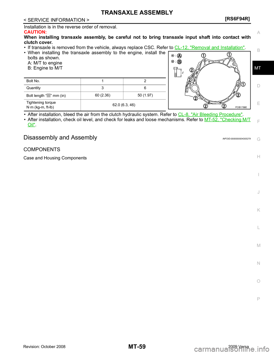
• When installing the transaxle assembly to the engine, install the
bolts as shown.
A: M/T to engine
B: Engine to M/T
• After installation, bleed the air from the clutch hydraulic system. Refer to CL-8, " Air Bleeding Procedure " .
• After installation, check oil level, and check for leaks and loose mechanisms. Refer to MT-52, " Checking M/T
Oil " .
Disassembly and Assembly INFOID:0000000004305279
COMPONENTS
Case and Housing Components Bolt No. 1 2
Quantity 3 6
Bolt length “ ” mm (in) 60 (2.36) 50 (1.97)
Tightening torque
N·m (kg-m, ft-lb) 62.0 (6.3, 46)
Page 3896 of 4331
MTC
N
O P
PREPARATION
HFC-134a (R-134a) Servic e Tool and Equipment INFOID:0000000004307051
Never mix HFC-134a refrigerant and/or its specified oil with CFC-12 (R-12) refrigerant and/or its oil.
Separate and non-interchangeable service equipment must be used for handling each type of refrigerant/oil.
Refrigerant container fittings, service hose fittings and service equipment fittings (equipment which handles
refrigerant and/or oil) are different between CFC-12 (R-12) and HFC-134a (R-134a). This is to avoid mixed
use of the refrigerants/oil.
Adapters that convert one size fitting to another must never be used refrigerant/oil contamination will occur
and compressor failure will result.
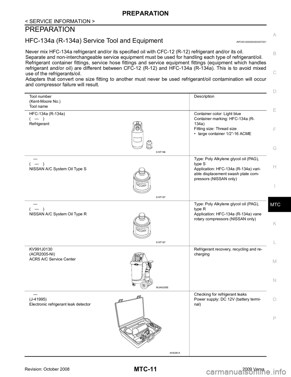
Tool number
(Kent-Moore No.)
Tool name Description
HFC-134a (R-134a)
( — )
Refrigerant Container color: Light blue
Container marking: HFC-134a (R-
134a)
Fitting size: Thread size
• large container 1/2”-16 ACME
—
( — )
NISSAN A/C System Oil Type S Type: Poly Alkylene glycol oil (PAG),
type S
Application: HFC-134a (R-134a) vari-
able displacement swash plate com-
pressors (NISSAN only)
—
( — )
NISSAN A/C System Oil Type R Type: Poly Alkylene glycol oil (PAG),
type R
Application: HFC-134a (R-134a) vane
rotary compressors (NISSAN only)
KV991J0130
(ACR2005-NI)
ACR5 A/C Se rvice Center Refrigerant recovery, recycling and re-
charging
—
(J-41995)
Electronic refrigerant leak detector Checking for refrigerant leaks
Power supply: DC 12V (battery termi-
nal) S-NT197
WJIA0293E
AHA281A