2009 NISSAN LATIO checking oil
[x] Cancel search: checking oilPage 2443 of 4331

BASIC SERVICE PROCEDURE
EC-1087
< SERVICE INFOMATION >
[MR TYPE 2] C
D E
F
G H
I
J
K L
M A EC
NP
O
1. Remove fuel pump fuse (1) located in IPDM E/R (2).
• : Vehicle front
2. Start engine.
3. After engine stalls, crank it two or three times to release all fuel pressure.
4. Turn ignition switch OFF.
5. Reinstall fuel pump fuse after servicing fuel system.
FUEL PRESSURE CHECK CAUTION:
Before disconnecting fuel line, release fuel pressure from fuel line to eliminate danger.
NOTE:
• Prepare pans or saucers under the disconnected fuel line because the fuel may spill out. The fuel
pressure cannot be completely released because C11 models do not have fuel return system.
• The fuel hose connection method u sed when taking fuel pressure check must not be used for other
purposes.
• Be careful not to scratch or put debris around connection area when servicing, so that the quick
connector maintains seal abil ity with O-rings inside.
• Do not perform fuel pressure check with electrical syst ems operating (i.e. lights, rear defogger, A/C,
etc.) Fuel pressure gauge may indicate false readin gs due to varying engine load and changes in
manifold vacuum.
1. Release fuel pressure to zero. Refer to "FUEL PRESSURE RELEASE".
2. Prepare fuel hose for fuel pressure check B and fuel tube adapter (KV10118400) D, then connect fuel pressure gauge A.
• : To quick connector
• : To fuel tube (engine side)
• C: Clamp
• Use suitable fuel hose for fuel pressure check (genuine
NISSAN fuel hose without quick connector).
• To avoid unnecessary force or tension to hose, use moder- ately long fuel hose for fuel pressure check.
• Do not use the fuel hose for checking fuel pressure with dam- age or cracks on it.
• Use Pressure Gauge to check fuel pressure.
3. Remove fuel hose. Refer to EM-156, " Removal and Installation " .
• Do not twist or kink fuel hose because it is plastic hose.
4. Connect fuel hose for fuel pressure check (1) to fuel tube (engine side) with clamp (2) as shown in the figure.
• No.2 spool (5)
• Wipe off oil or dirt from hose insertion part using cloth moist-
ened with gasoline.
• Apply proper amount of gasoline between top of the fuel tube (3) and No.1 spool (4).
• Insert fuel hose for fuel pressure check until it touches the No.1 spool on fuel tube.
• Use NISSAN genuine hose clamp (part number: 16439 N4710
or 16439 40U00).
• When reconnecting fuel line, always use new clamps.
• Use a torque driver to tighten clamps.
• Install hose clamp to the positi on within 1 - 2 mm (0.04 - 0.08 in).
• Make sure that clamp screw does not contact adjacent parts. PBIB2958E
Tightening torque: 1 - 1.5 N·m
(0.1 - 0.15 kg-m, 9 - 13 in-lb) PBIB2982E
PBIB2983E
Page 2641 of 4331

DTC P0300 - P0304 MULTIPLE CYLINDER
MISFIRE, NO. 1 - 4 CYLINDER MIS-
FIRE
EC-1285
< SERVICE INFOMATION >
[MR TYPE 2] C
D E
F
G H
I
J
K L
M A EC
NP
O
Yes >> GO TO 4.
No >> GO TO 9. 4.
CHECK FUEL INJECTOR
Does each fuel injector make an operating sound at idle?
Yes or No Yes >> GO TO 5.
No >> Check fuel injector(s) and circuit(s). Refer to EC-1508 .
5.
CHECK FUNCTION OF IGNITION COIL-I
CAUTION:
Do the following procedure in the place where ventilation is good without the combustible.
1. Turn ignition switch OFF.
2. Remove fuel pump fuse (1) in IPDM E/R (2) to release fuel pres- sure.
NOTE:
Do not use CONSULT-III to release fuel pressure, or fuel pres-
sure applies again during the following procedure.
- : Vehicle front
3. Start engine.
4. After engine stalls, crank it two or three times to release all fuel
pressure.
5. Turn ignition switch OFF.
6. Remove all ignition coil harness connectors to avoid the electri-
cal discharge from the ignition coils.
7. Remove ignition coil and spark plug of the cylinder to be checked.
8. Crank engine for 5 seconds or more to remove combustion gas in the cylinder.
9. Connect spark plug and harness connector to ignition coil.
10. Fix ignition coil using a rope etc. with gap of 13 - 17 mm (0.52 - 0.66 in) between the edge of the spark plug and grounded metal
portion as shown in the figure.
11. Crank engine for about 3 seconds, and check whether spark is generated between the spark plug and the grounded metal por-
tion.
CAUTION:
• Do not approach to the spar k plug and the ignition coil
within 50cm. Be careful not to get an electrical shock
while checking, because the el ectrical discharge voltage
becomes 20kV or more.
• It might cause to damage the igni tion coil if the gap of more than 17 mm (0.66 in) is taken.
NOTE:
When the gap is less than 13 mm (0.52 in), the sp ark might be generated even if the coil is mal-
functioning.
OK or NG OK >> GO TO 9.
NG >> GO TO 6. 6.
CHECK FUNCTION OF IGNITION COIL-II
1. Turn ignition switch OFF.
2. Disconnect spark plug and connect a known-good spark plug. PBIB3332E
Spark should be generated. PBIB2958E
PBIB2325E
Page 2642 of 4331

EC-1286< SERVICE INFOMATION >
[MR TYPE 2]
DTC P0300 - P0304 MULTIPLE CYLINDER
MISFIRE, NO. 1 - 4 CYLINDER MIS-
FIRE
3. Crank engine for about 3 seconds, and recheck whether spark is generated between the spark plug and the grounded metal portion.
OK or NG OK >> GO TO 7.
NG >> Check ignition coil, power transistor and their circuits. Refer to EC-1518 .
7.
CHECK SPARK PLUG
Check the initial spark plug for fouling, etc.
OK or NG OK >> Replace spark plug(s) with standard type one(s). For
spark plug type, refer to EM-227, " Standard and Limit " .
NG >> 1. Repair or clean spark plug. 2. GO TO 8. 8.
CHECK FUNCTION OF IGNITION COIL-III
1. Reconnect the initial spark plugs.
2. Crank engine for about three seconds, and recheck whether spark is generated between the spark plug
and the grounded portion.
OK or NG OK >>
INSPECTION END
NG >> Replace spark plug(s) with standard type one(s). For spark plug type, refer to EM-227, " Standard
and Limit " .
9.
CHECK COMPRESSION PRESSURE
Check compression pressure. Refer to EM-185, " On-Vehicle Service " .
OK or NG OK >> GO TO 10.
NG >> Check pistons, piston rings, valves, valve seats and cylinder head gaskets. 10.
CHECK FUEL PRESSURE
1. Install all removed parts.
2. Release fuel pressure to zero. Refer to EC-1086, " Fuel Pressure Check " .
3. Install fuel pressure gauge and check fuel pressure. Refer to EC-1086, " Fuel Pressure Check " .
OK or NG OK >> GO TO 12.
NG >> GO TO 11. 11.
DETECT MALFUNCTIONING PART
Check the following.
• Fuel pump and circuit (Refer to EC-1513 .)
• Fuel pressure regulator (Refer to EC-1086, " Fuel Pressure Check " .)
• Fuel lines (Refer to FL-4, " Checking Fuel Line " .)
• Fuel filter for clogging
>> Repair or replace.
Spark should be generated.
SEF156I
Spark should be generated.
At idling: Approximately 350 kPa (3.57 kg/cm 2
, 51 psi)
Page 2663 of 4331

DTC P0420 THREE WAY CATALYST FUNCTION
EC-1307
< SERVICE INFOMATION >
[MR TYPE 2] C
D E
F
G H
I
J
K L
M A EC
NP
O
OK or NG OK >> GO TO 5.
NG >> Follow the EC-1078, " Basic Inspection " .
5.
CHECK FUEL INJECTOR
1. Stop engine and turn ignition switch OFF.
2. Disconnect ECM harness connector.
3. Turn ignition switch ON.
4. Check voltage between ECM terminals 25, 29, 30, 31 and ground with CONSULT-III or tester.
Refer to Wiring Diagram for fuel injectors, EC-1509, " Wiring Diagram " .
OK or NG OK >> GO TO 6.
NG >> Perform EC-1510, " Diagnosis Procedure " .
6.
CHECK FUNCTION OF IGNITION COIL-I
CAUTION:
Do the following procedure in the place where ventilation is good without the combustible.
1. Turn ignition switch OFF.
2. Remove fuel pump (1) fuse in IPDM E/R (2) to release fuel pres-
sure.
NOTE:
Do not use CONSULT-III to release fuel pressure, or fuel pres-
sure applies again during the following procedure.
- : Vehicle front
3. Start engine.
4. After engine stalls, crank it two or three times to release all fuel pressure.
5. Turn ignition switch OFF.
6. Remove all ignition coil harness connectors to avoid the electri- cal discharge from the ignition coils.
7. Remove ignition coil and spark plug of the cylinder to be checked.
8. Crank engine for 5 seconds or more to remove combustion gas in the cylinder.
9. Connect spark plug and harness connector to ignition coil.
10. Fix ignition coil using a rope etc. with gap of 13 - 17 mm (0.52 - 0.66 in) between the edge of the spark plug and grounded metal
portion as shown in the figure.
11. Crank engine for about 3 seconds, and check whether spark is
generated between the spark plug and the grounded metal por-
tion.
CAUTION:
• Do not approach to the spar k plug and the ignition coil
within 50cm. Be careful not to get an electrical shock
while checking, because the el ectrical discharge voltage
becomes 20kV or more. Items Specifications
Target idle speed A/T: 700
± 50 rpm (in P or N position)
CVT: 700 ± 50 rpm (in P or N position)
M/T: 700 ± 50 rpm (in Neutral position)
Ignition timing A/T: 13
± 5 ° BTDC (in P or N position)
CVT: 13 ± 5 ° BTDC (in P or N position)
M/T: 13 ± 5 ° BTDC (in Neutral position) Voltage: Battery voltage
Spark should be generated. PBIB2958E
PBIB2325E
Page 2882 of 4331

EC-1526< SERVICE INFOMATION >
[MR TYPE 2]
IGNITION SIGNAL
7. Remove fuel pump fuse (1) in IPDM E/R (2) to release fuel pres- sure.
NOTE:
Do not use CONSULT-III to releas e fuel pressure, or fuel pres-
sure applies again during the following procedure.
- : Vehicle front
8. Start engine.
9. After engine stalls, crank it two or three times to release all fuel
pressure.
10. Turn ignition switch OFF.
11. Remove all ignition coil harness connectors to avoid the electri-
cal discharge from the ignition coils.
12. Remove ignition coil and spark plug of the cylinder to be checked.
13. Crank engine for 5 seconds or more to remove combustion gas in the cylinder.
14. Connect spark plug and harness connector to ignition coil.
15. Fix ignition coil using a rope etc. with gap of 13 - 17 mm (0.52 - 0.66 in) between the edge of the spark plug and grounded metal
portion as shown in the figure.
16. Crank engine for about 3 seconds, and check whether spark is generated between the spark plug and the grounded metal por-
tion.
CAUTION:
• Do not approach to the spar k plug and the ignition coil
within 50cm. Be careful not to get an electrical shock
while checking, because the el ectrical discharge voltage
becomes 20kV or more.
• It might cause to damage the igni tion coil if the gap of more than 17 mm (0.66 in) is taken.
NOTE:
When the gap is less than 13 mm (0.52 in), the sp ark might be generated even if the coil is mal-
functioning.
17. If NG, replace ignition coil with power transistor.
CONDENSER-2
1. Turn ignition switch OFF.
2. Disconnect condenser-2 harness connector.
3. Check resistance between condenser-2 terminals 1 and 2.
4. If NG, replace condenser-2.
Removal and Installation INFOID:0000000004500425
IGNITION COIL WITH POWER TRANSISTOR
Refer to EM-153 .
Spark should be generated. PBIB2958E
PBIB2325E
Resistance: Above 1 M
Ω [at 25 °C (77 °F)] PBIB0794E
Page 2948 of 4331
EM
N
O P
CONTENTS
ENGINE MECHANICAL
HR16DE
PRECAUTION ....... ........................................
4
PRECAUTIONS .............................................. .....4
Precaution for Supplemental Restraint System
(SRS) "AIR BAG" and "SEAT BELT PRE-TEN-
SIONER" ............................................................. ......
4
Precaution Necessary fo r Steering Wheel Rota-
tion After Battery Disconnect ............................... ......
4
Precaution for Procedure without Cowl Top Cover ......5
Precaution for Drain Cool ant .....................................5
Precaution for Disconnecting Fuel Piping ........... ......5
Precaution for Removal and Disassembly ................5
Precaution for Inspection, Repair and Replace-
ment .................................................................... ......
5
Precaution for Assembly and Installation ..................5
Parts Requiring Angular Tightening ..........................6
Precaution for Liquid Gasket ............................... ......6
PREPARATION .... ........................................8
PREPARATION .............................................. .....8
Special Service Tools .......................................... ......8
Commercial Service Tools .................................. ......9
SYMPTOM DIAGNOSIS ..... .........................12
NOISE, VIBRATION AND HARSHNESS
(NVH) TROUBLESHOOTING ........................ ....
12
NVH Troubleshooting - Engine Noise ................. ....12
Use the Chart Below to Help You Find the Cause
of the Symptom ................................................... ....
13
ON-VEHICLE MAINTENA NCE ....................14
DRIVE BELTS ................................................ ....14
Checking ............................................................. ....14
Tension Adjustment ............................................ ....14
Removal and Installation .........................................15
AIR CLEANER FILTER .................................. ....17 Removal and Installation .....................................
....17
SPARK PLUG ................................................... 18
Exploded View ..................................................... ....18
Removal and Installation ..................................... ....18
CAMSHAFT VALVE CLEARANCE .................. 20
Inspection and Adjustment .................................. ....20
COMPRESSION PRESSURE ........................... 23
Inspection ............................................................ ....23
ON-VEHICLE REPAIR ..... ............................24
DRIVE BELT IDLER PULLEY .......................... 24
Exploded View ..................................................... ....24
Removal and Installation ..................................... ....24
AIR CLEANER AND AIR DUCT ....................... 26
Exploded View ..................................................... ....26
Removal and Installation ..................................... ....26
Inspection ............................................................ ....27
INTAKE MANIFOLD ......................................... 28
Exploded View ..................................................... ....28
Removal and Installation ..................................... ....28
EXHAUST MANIFOLD ...................................... 31
Exploded View ..................................................... ....31
Removal and Installation ..................................... ....31
FUEL INJECTOR AND FUEL TUBE ................ 34
Exploded View ..................................................... ....34
Removal and Installation ..................................... ....34
Inspection ............................................................ ....38
OIL PAN (LOWER) ........................................... 39
Exploded View ..................................................... ....39
Removal and Installation ..................................... ....39
Inspection ............................................................ ....41
OIL PAN (UPPER) AND OIL STRAINER ......... 42
Component .......................................................... ....42
Page 2962 of 4331

DRIVE BELTS
EM-15
< ON-VEHICLE MAINTENANCE >
[HR16DE] C
D E
F
G H
I
J
K L
M A EM
NP
O
• When the lock nut is loosened excessively, the idle
r pulley tilts and the correct tension adjust-
ment cannot be performed. Never loo sen it excessively (more than 45 degrees).
• Put a matching mark on the lock nut, and check turning angle with a protractor. Never visually
check the tightening angle.
2. Adjust the belt tension by turning the adjusting bolt. CAUTION:
• When checking immediately after in stallation, first adjust it to the specified value. Then, after
turning crankshaft two turns or more, re-adjust to the specified value to avoid variation in deflec-
tion between pulleys.
• When the tension adjustment is performed, the lo ck nut should be in the condition at step“2”. If
the tension adjustment is performed when the lo ck nut is loosened more than the standard, the
idler pulley tilts and the correct tens ion adjustment cannot be performed.
3. Tighten the idler pulley lock nut.
Removal and Installation INFOID:0000000004784271
REMOVAL 1. Loosen the idler pulley lock nut (A), and then adjust the belt ten- sion by turning the adjusting bolt (B).
2. Remove drive belt.
INSTALLATION 1. Pull the idler pulley in the loosening direction, and then tempo- rarily tighten the idler pulley lock nut (A) to the following torque.
NOTE:
Do not move the lock nut from the tightened position. Proceed to step “2”.
2. Install the drive belt to each pulley. CAUTION:
• Make sure that there is no oil, grease, or coolant, etc. in pulley grooves.
• Make sure that the belt is securely inside the groove on each pulley.
3. Adjust drive belt tension by turning the adjusting bolt. Refer to EM-14, " Tension Adjustment " .
CAUTION: Idler pulley lock nut : 34.8 N·m (3.5 kg-m, 26 ft-lb)
1 : Generator
2 : Water pump
3 : Crankshaft pulley
4 : A/C compressor (with A/C models)
: Idler pulley (without A/C models)
5 : Idler pulley
6 : Drive belt PBIC3643E
1 : Generator
2 : Water pump
3 : Crankshaft pulley
4 : A/C compressor (with A/C models)
: Idler pulley (without A/C models)
5 : Idler pulley
6 : Drive belt
B : Adjusting bolt
Idler pulley lock nut : 4.4 N·m (0.45 kg-m, 39 in-lb)
(temporary tightening) PBIC3643E
Page 2970 of 4331
EM
NP
O
COMPRESSION PRESSURE
Inspection INFOID:0000000004784276
1. Warm up engine thoroughly. Then, stop it.
2. Release fuel pressure. Refer to EC-498, " Inspection " .
3. Remove ignition coil and spark plug from each cylinder. Refer to EM-46, " Exploded View " .
4. Connect an engine tachometer (not required in use of CONSULT-III).
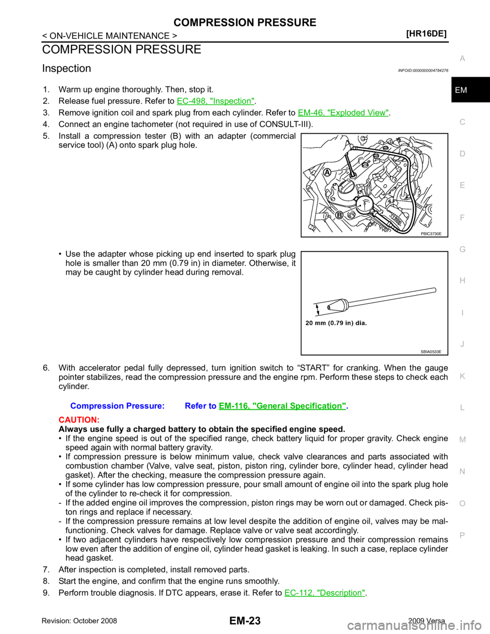
5. Install a compression tester (B) with an adapter (commercial service tool) (A) onto spark plug hole.
• Use the adapter whose picking up end inserted to spark plug hole is smaller than 20 mm (0.79 in) in diameter. Otherwise, it
may be caught by cylinder head during removal.
6. With accelerator pedal fully depressed, turn ignition switch to “START” for cranking. When the gauge pointer stabilizes, read the compression pressure and the engine rpm. Perform these steps to check each
cylinder.
CAUTION:
Always use fully a charged battery to obtain the specified engine speed.
• If the engine speed is out of the specified range, c heck battery liquid for proper gravity. Check engine
speed again with normal battery gravity.
• If compression pressure is below minimum value, check valve clearances and parts associated with combustion chamber (Valve, valve seat, piston, pi ston ring, cylinder bore, cylinder head, cylinder head
gasket). After the checking, measure the compression pressure again.
• If some cylinder has low compression pressure, pour small amount of engine oil into the spark plug hole
of the cylinder to re-check it for compression.
- If the added engine oil improves the compression, piston rings may be worn out or damaged. Check pis-
ton rings and replace if necessary.
- If the compression pressure remains at low level despite the addition of engine oil, valves may be mal- functioning. Check valves for damage. Replace valve or valve seat accordingly.
• If two adjacent cylinders have respectively low compression pressure and their compression remains low even after the addition of engine oil, cylinder head gasket is leaking. In such a case, replace cylinder
head gasket.
7. After inspection is completed, install removed parts.
8. Start the engine, and confirm that the engine runs smoothly.
9. Perform trouble diagnosis. If DTC appears, erase it. Refer to EC-112, " Description " . SBIA0533E
General Specification " .