Page 208 of 4331

TROUBLE DIAGNOSIS FOR SYMPTOMS
AT-203
< SERVICE INFORMATION >
D
E
F
G H
I
J
K L
M A
B AT
N
O P
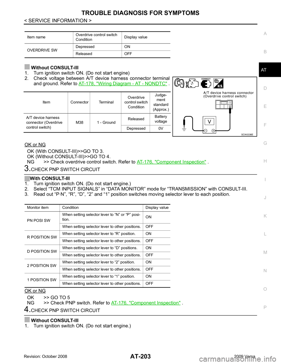
Without CONSULT-III
1. Turn ignition switch ON. (Do not start engine)
2. Check voltage between A/T device harness connector terminal and ground. Refer to AT-178, " Wiring Diagram - AT - NONDTC " .
OK or NG OK (With CONSULT-III)>>GO TO 3.
OK (Without CONSULT-III)>>GO TO 4.
NG >> Check overdrive control switch. Refer to AT-176, " Component Inspection " .
3.
CHECK PNP SWITCH CIRCUIT
With CONSULT-III
1. Turn ignition switch ON. (Do not start engine.)
2. Select “TCM INPUT SIGNALS” in “DATA MONI TOR” mode for “TRANSMISSION” with CONSULT-III.
3. Read out “P·N”, “R”, “D”, “2” and “1” position switches moving selector lever to each position.
OK or NG OK >> GO TO 5
NG >> Check PNP switch. Refer to AT-176, " Component Inspection " .
4.
CHECK PNP SWITCH CIRCUIT
Without CONSULT-III
1. Turn ignition switch ON. (Do not start engine.) Item name
Overdrive control switch
Condition Display value
OVERDRIVE SW Depressed ON
Released OFF Item Connector Terminal
Overdrive
control switch Condition Judge-
ment
standard
(Approx.)
A/T device harness
connector (Overdrive
control switch) M38 1 - Ground
Released
Battery
voltage
Depressed 0V SCIA5336E
Monitor item Condition Display value
PN POSI SW When setting selector le
ver to “N” or “P” posi-
tion. ON
When setting selector lever to other positions. OFF
R POSITION SW When setting selector lever to “R” position. ON
When setting selector lever to other positions. OFF
D POSITION SW When setting selector lever to “D” positions. ON
When setting selector lever to other positions. OFF
2 POSITION SW When setting selector lever to “2” position. ON
When setting selector lever to other positions. OFF
1 POSITION SW When setting selector lever to “1” position. ON
When setting selector lever to other positions. OFF
Page 212 of 4331
AT
N
O P
A/T SHIFT LOCK SYSTEM
Description INFOID:0000000004305498
• The mechanical key interlock mechanism also operates as a shift lock: With the ignition switch turned to ON, selector lever cannot be shifted from “P” position to any other position
unless brake pedal is depressed.
With the key removed, selector lever cannot be shifted from “P” position to any other position.
The key cannot be removed unless selector lever is placed in “P” position.
• The shift lock and key interlock mechanisms are controlled by the ON-OFF operation of the shift lock sole-
noid and by the operation of the rotator and sli der located inside key cylinder, respectively.
Shift Lock System Parts Location INFOID:0000000004305499
1. Key interlock cable 2. Key cylinder 3. Stop lamp switch
4. Brake pedal 5. Shift lock release button 6. Key interlock cable
7. Shift lock solenoid 8. Park position switch
Page 214 of 4331
AT
N
O P
•
Selector lever can be moved fr om “P” position with ignition key in ON position and brake pedal
released.
• Selector lever can be moved from “P” position when ignition switch is removed from key cylinder.
SYMPTOM 2:
• Ignition key cannot be removed when sel ector lever is set to “P” position.
• Ignition key can be removed wh en selector lever is set to any position except “P” position.OK >> GO TO 2.
NG >> Repair key interlock cable. Refer to AT-218, " Removal and Installation " .
Checking of A/T Position " .
OK or NG OK >> GO TO 3.
NG >> Adjust control cable. Refer to AT-216, " Adjustment of A/T Position " .
OK >>
INSPECTION END
NG >> GO TO 4. OK >> GO TO 7.
NG >> GO TO 5.
Page 221 of 4331

.
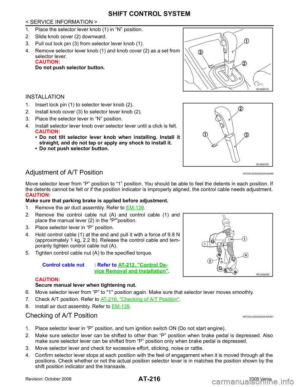
2. Remove the control cable nut (A) and control cable (1) and place the manual lever (2) in the "P'"position.
3. Place selector lever in “P” position.
4. Hold control cable (1) at the end and pull it with a force of 9.8 N (approximately 1 kg, 2.2 lb). Release the control cable and tem-
porarily tighten control cable nut (A).
5. Tighten control cable nut (A) to the specified torque.
CAUTION:
Secure manual lever when tightening nut.
6. Move selector lever from “P” to "1" position again. Make sure that selector lever moves smoothly.
7. Check A/T position. Refer to AT-216, " Checking of A/T Position " .
8. Install air duct assembly. Refer to EM-139 .
Checking of A/T Position INFOID:0000000004305497
1. Place selector lever in “P” position, and tu rn ignition switch ON (Do not start engine).
2. Make sure selector lever can be shifted to other than “P” position when brake pedal is depressed. Also
make sure selector lever can be shifted from “P” position only when brake pedal is depressed.
3. Move selector lever and check for excessive effort, sticking, noise or rattle.
4. Confirm selector lever stops at each position with the feel of engagement when it is moved through all the
positions. Check whether or not the actual position sele ctor lever is in matches the position shown by the
shift position indicator and the transaxle. SCIA6972E
Control De-
vice Removal and Installation " .
Page 224 of 4331

AT
N
O P
7. Remove steering column cover (upper and lower) and instru-
ment lower finisher. Refer to IP-11 .
8. Pull out the lock plate (A) from the holder (B).
9. Remove the key interlock cable (1) from the key cylinder (2).
10. Remove the clip (A), and then remove the key interlock cable (1).
INSTALLATION CAUTION:
• Install key interlock cable in such a way that it will not be damaged by sharp bends, twists or interfer-
ence with adjacent parts.
• After installing key interlock cable to contro l device assembly, make sure that casing cap and
bracket are firmly secured in their positions.
1. Place the selector lever in the “P” position.
2. Turn ignition switch to “ACC” or “ON” position.
3. Set the key interlock cable (1) to the key cylinder (2).
4. Install the lock plate (A) to the holder (B).
5. Turn ignition switch to “LOCK” position.
6. Temporarily install the adjust holder (A) to the key interlock rod (B).
7. Install the casing cap (C) to the cable bracket (D) on the control device assembly.
CAUTION:
• Do not bend or twist key interlock cable excessively when
installing.
• After installing key interlo ck cable to cable bracket (D) on
control device assembly, make sure casing cap (C) is
firmly secured in cable bracket (D) on control device
assembly.
• If casing cap (C) is loose [less than 39.2 N (4.0 kg, 8.8 lb)
removing force], replace key interlock cable.
Page 389 of 4331

AV
N
O P
• to audio unit terminal 21 (with premium system)
• through body grounds M57 and M61 and
• to subwoofer terminal 3 (with premium system)
• through body grounds B7 and B19.
Then audio signals are supplied
• through audio unit terminals 2, 3, 4, 5, 11, 12, 13, and 14
• to terminals + and - of front door speaker LH and RH and
• to terminals + and - of tweeter LH and RH and
• to terminals + and - of rear door speaker LH and RH and
• to terminals 2 and 6 of subwoofer (with premium system).
Steering Wheel Audio Contro l Switches (with Bluetooth)
When one of steering wheel audio control switches is pus hed, the resistance in steering switch circuit changes
depending on which button is pushed.
Satellite Radio Tuner (Pre-wiring) The satellite radio tuner pre-wiring allows connection of a satellite radio tuner.
Power is supplied at all times
• through 20A fuse (No. 27, located in the fuse and fusible link box)
• to satellite radio tuner pre-wiring terminal 32.
With the ignition switch in the ACC or ON position, power is supplied
• through 10A fuse (No. 20, located in the fuse and fusible link box)
• to satellite radio tuner pre-wiring terminal 36.
Then audio signals are supplied
• through satellite radio tuner pre-wiring terminals 21, 22, 23 and 24
• to audio unit terminals 41, 42, 43 and 44.
Satellite Radio Tuner (Factory Installed)
Power is supplied at all times
• through 20A fuse (No. 27, located in the fuse and fusible link box)
• to satellite radio tuner terminal 32.
With the ignition switch in the ACC or ON position, power is supplied
• through 10A fuse (No. 20, located in the fuse and fusible link box)
• to satellite radio tuner terminal 36.
Ground is supplied through the case of the satellite radio tuner.
Then audio signals are supplied
• through satellite radio tuner terminals 21, 22, 23 and 24
• to audio unit terminals 41, 42, 43 and 44.
Ground is supplied through the case of the satellite radio tuner.
SPEED SENSITIVE VOLUME SYSTEM (MID LEVEL AND PREMIUM SYSTEM) Volume level of this system goes up and down automatica lly in proportion to the vehicle speed. The control
level can be selected by the customer. Refer to Owner's Manual for operating instructions.
Page 403 of 4331

AUDIO
AV-19
< SERVICE INFORMATION >
C
D E
F
G H
I
J
L
M A
B AV
N
O P
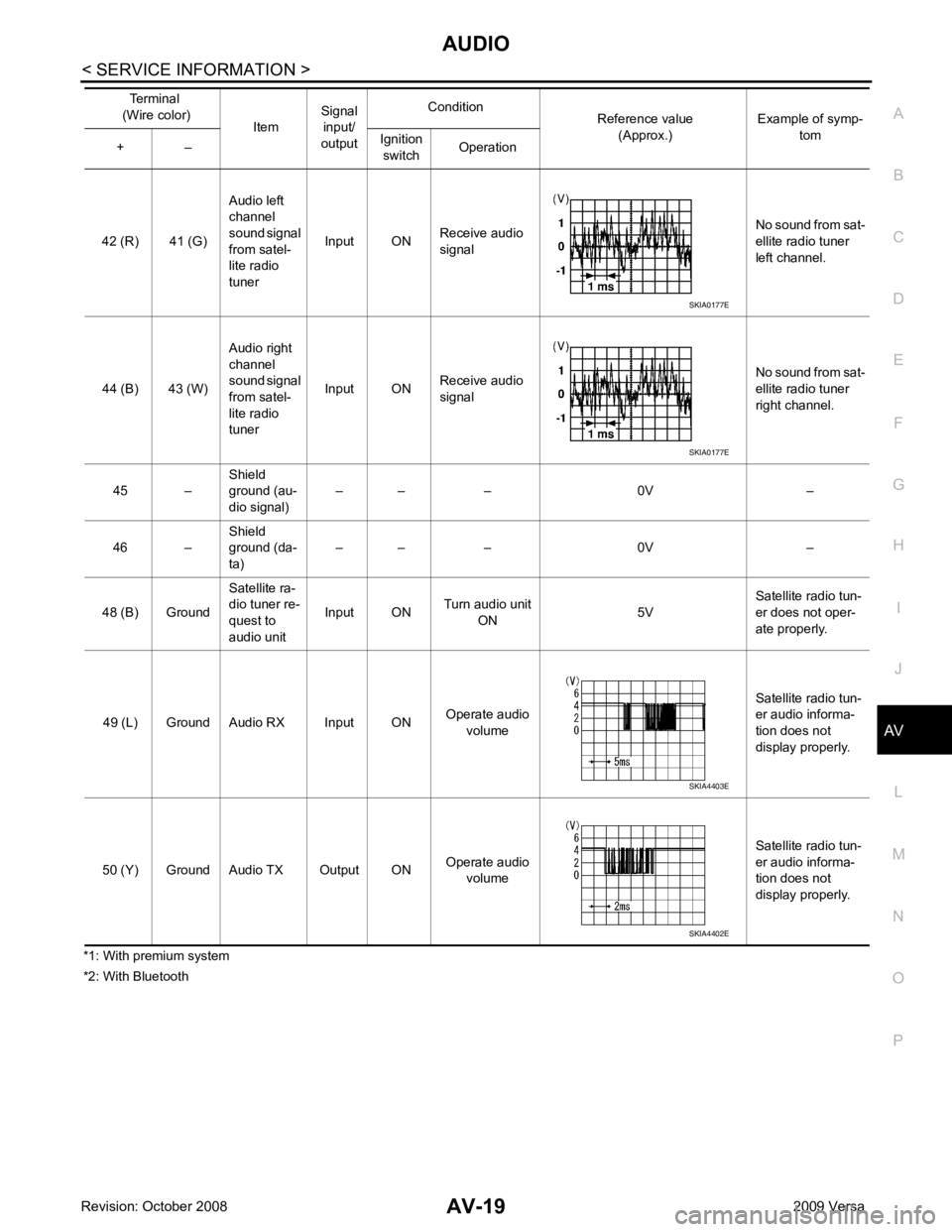
*1: With premium system
*2: With Bluetooth 42 (R) 41 (G)
Audio left
channel
sound signal
from satel-
lite radio
tuner Input ON
Receive audio
signal No sound from sat-
ellite radio tuner
left channel.
44 (B) 43 (W) Audio right
channel
sound signal
from satel-
lite radio
tuner Input ON
Receive audio
signal No sound from sat-
ellite radio tuner
right channel.
45 – Shield
ground (au-
dio signal) – – – 0V –
46 – Shield
ground (da-
ta) – – – 0V –
48 (B) Ground Satellite ra-
dio tuner re-
quest to
audio unit Input ON
Turn audio unit
ON 5VSatellite radio tun-
er does not oper-
ate properly.
49 (L) Ground Audio RX Input ON Operate audio
volume Satellite radio tun-
er audio informa-
tion does not
display properly.
50 (Y) Ground Audio TX Output ON Operate audio
volume Satellite radio tun-
er audio informa-
tion does not
display properly.
Terminal
(Wire color) ItemSignal
input/
output Condition
Reference value
(Approx.) Example of symp-
tom
+ – Ignition
switch Operation SKIA0177E
SKIA0177E
SKIA4403E
SKIA4402E
Page 405 of 4331

AUDIO
AV-21
< SERVICE INFORMATION >
C
D E
F
G H
I
J
L
M A
B AV
N
O P
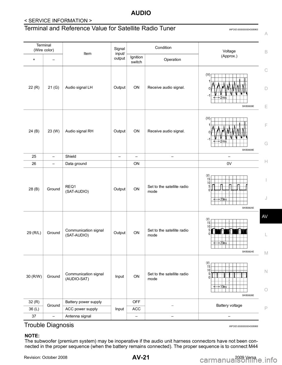
Terminal and Reference Valu
e for Satellite Radio Tuner INFOID:0000000004306965
Trouble Diagnosis INFOID:0000000004306966
NOTE:
The subwoofer (premium system) may be inoperative if the audio unit harness connectors have not been con-
nected in the proper sequence (when the battery remain s connected). The proper sequence is to connect M44
Terminal
(Wire color) ItemSignal
input/
output Condition
Voltage
(Approx.)
+ – Ignition
switch Operation
22 (R) 21 (G) Audio signal LH Output ON Receive audio signal.
24 (B) 23 (W) Audio signal RH Output ON Receive audio signal. 25 – Shield – – – –
26 – Data ground ON 0V
28 (B) Ground REQ1
(SAT-AUDIO) Output ONSet to the satellite radio
mode
29 (R/L) Ground Communication signal
(SAT-AUDIO) Output ONSet to the satellite radio
mode
30 (R/W) Ground Communication signal
(AUDIO-SAT) Input ON
Set to the satellite radio
mode
32 (R) GroundBattery power supply
InputOFF
− Battery voltage
36 (L) ACC power supply ACC
37 – Antenna signal – – – SKIB3609E
SKIB3609E
SKIB3825E
SKIB3824E
SKIB3826E