2009 NISSAN LATIO display
[x] Cancel search: displayPage 3617 of 4331
LT
N
O P
How to Perform Trouble Diagnosis
INFOID:0000000004306527
1. Confirm the symptom or customer complaint.
2. Understand operation, description and function description. Refer to LT-4, " System Description " .
3. Perform the Preliminary Check. Refer to LT-11, " Preliminary Check " .
4. Check symptom and repair or replace the cause of the malfunction.
5. Do the headlamps operate normally? If YES, GO TO 6. If NO, GO TO 4.
6. INSPECTION END
Preliminary Check INFOID:0000000004306528
CHECK POWER SUPPLY AND GROUND CIRCUIT FOR BCM Refer to BCS-15, " BCM Power Supply and Ground Circuit Inspection " .
CHECK POWER SUPPLY AND GROUND CIRCUIT FOR IPDM E/R Refer to PG-26, " IPDM E/R Power/Ground Circuit Inspection " .
CONSULT-III Function (BCM) INFOID:0000000004306529
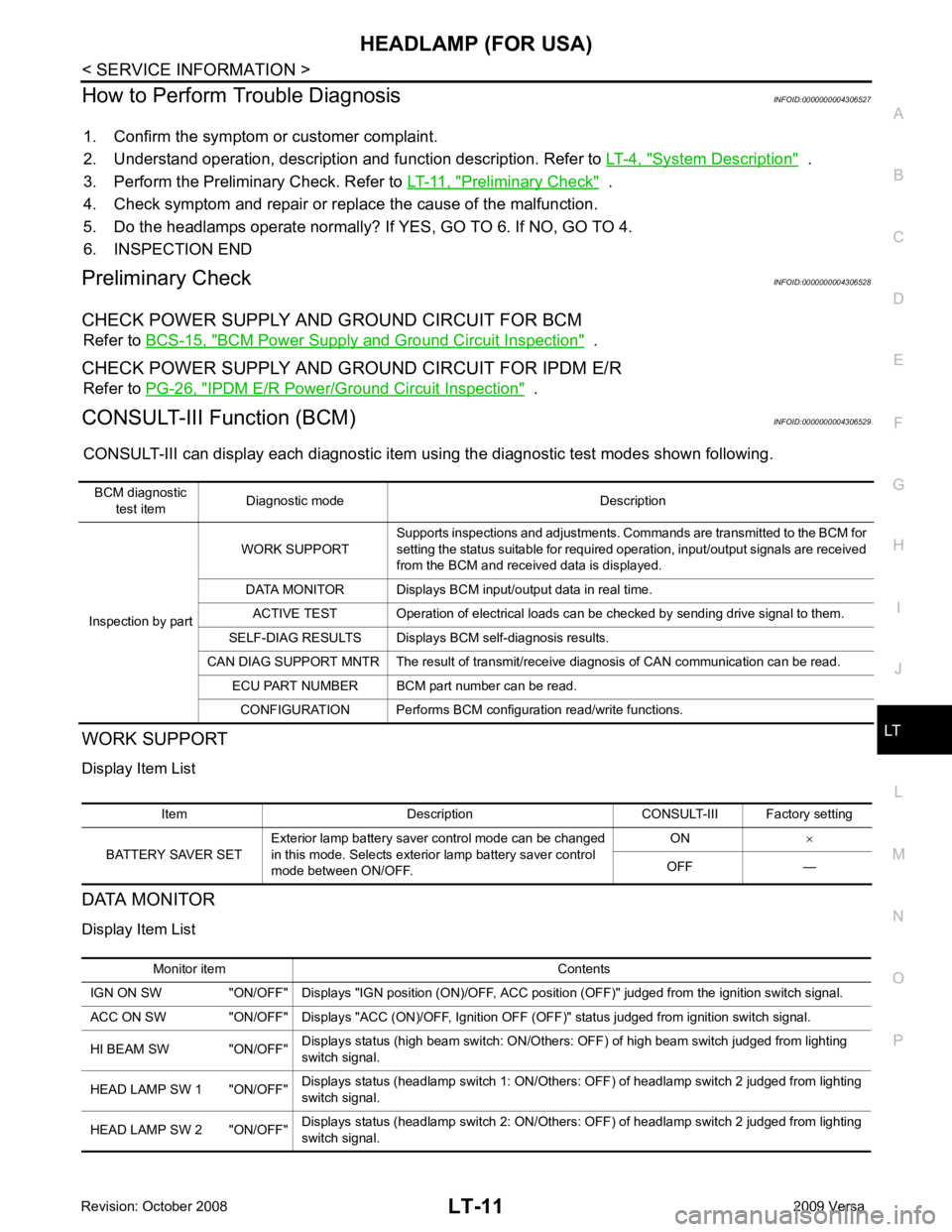
CONSULT-III can display each diagnostic item using the diagnostic test modes shown following.
WORK SUPPORT
Display Item List
DATA MONITOR
Display Item List BCM diagnostic
test item Diagnostic mode Description
Inspection by part WORK SUPPORT
Supports inspections and adjustments. Commands are transmitted to the BCM for
setting the status suitable for required operation, input/output signals are received
from the BCM and received data is displayed.
DATA MONITOR Displays BCM input/output data in real time. ACTIVE TEST Operation of electrical loads can be checked by sending drive signal to them.
SELF-DIAG RESULTS Displays BCM self-diagnosis results.
CAN DIAG SUPPORT MNTR The result of transmit/receive diagnosis of CAN communication can be read. ECU PART NUMBER BCM part number can be read.
CONFIGURATION Performs BCM configuration read/write functions. Item Description CONSULT-III Factory setting
BATTERY SAVER SET Exterior lamp battery saver control mode can be changed
in this mode. Selects exterior lamp battery saver control
mode between ON/OFF. ON
×
OFF — Monitor item Contents
IGN ON SW "ON/OFF" Displays "IGN position (ON)/OFF, ACC position (OFF)" judged from the ignition switch signal.
ACC ON SW "ON/OFF" Displays "ACC (ON)/OFF, Ignition OFF (OFF)" status judged from ignition switch signal.
HI BEAM SW "ON/OFF" Displays status (high beam switch: ON/Others: OFF) of high beam switch judged from lighting
switch signal.
HEAD LAMP SW 1 "ON/OFF" Displays status (headlamp switch 1: ON/Others: OFF) of headlamp switch 2 judged from lighting
switch signal.
HEAD LAMP SW 2 "ON/OFF" Displays status (headlamp switch 2: ON/Others: OFF) of headlamp switch 2 judged from lighting
switch signal.
Page 3618 of 4331

Test item Description
TAIL LAMP Allows tail lamp relay to operate by switching ON-OFF.
HEAD LAMP Allows headlamp relay (HI, LO) to operate by switching ON-OFF.
FR FOG LAMP Allows fog lamp relay to operate by switching ON-OFF. Monitored item CONSULT-llI display Description
CAN communication CAN communication [U1000] Malfunction is detected in CAN communication.
CAN communication system CAN communication system 1 to 6 [U1000] Malfunction is detected in CAN system. IPDM E/R diagnostic Mode Description
SELF-DIAG RESULTS Displays IPDM E/R self-diagnosis results. DATA MONITOR Displays IPDM E/R in put/output data in real time.
CAN DIAG SUPPORT MNTR The result of transmit/receive diagnosis of CAN communication can be read. ACTIVE TEST Operation of electrical loads can be checked by sending drive signal to them.
Page 3619 of 4331
LT
N
O P
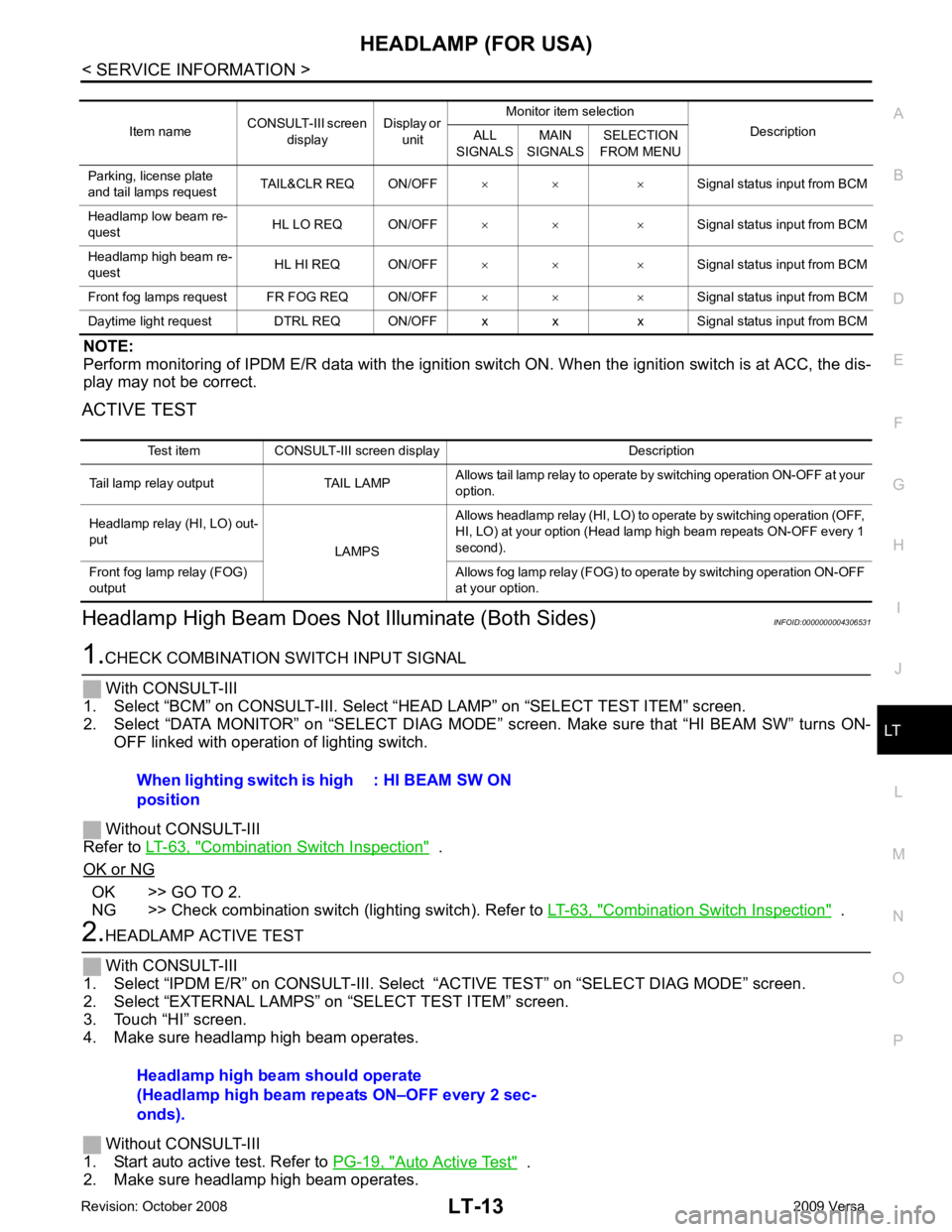
NOTE:
Perform monitoring of IPDM E/R data with the ignition swit ch ON. When the ignition switch is at ACC, the dis-
play may not be correct.
ACTIVE TEST
Headlamp High Beam Does No t Illuminate (Both Sides) INFOID:0000000004306531Combination Switch Inspection " .
OK or NG OK >> GO TO 2.
NG >> Check combination switch (lighting switch). Refer to LT-63, " Combination Switch Inspection " .
Auto Active Test " .
2. Make sure headlamp high beam operates. Item name
CONSULT-III screen
display Display or
unit Monitor item selection
Description
ALL
SIGNALS MAIN
SIGNALS SELECTION
FROM MENU
Parking, license plate
and tail lamps request TAIL&CLR REQ ON/OFF
× × ×Signal status input from BCM
Headlamp low beam re-
quest HL LO REQ ON/OFF
× × × Signal status input from BCM
Headlamp high beam re-
quest HL HI REQ ON/OFF
× × × Signal status input from BCM
Front fog lamps request FR FOG REQ ON/OFF × × ×Signal status input from BCM
Daytime light request DTRL REQ ON/OFF x x x Signal status input from BCM Test item CONSULT-III screen display Description
Tail lamp relay output TAIL LAMP Allows tail lamp relay to operate by switching operation ON-OFF at your
option.
Headlamp relay (HI, LO) out-
put LAMPSAllows headlamp relay (HI, LO) to operate by switching operation (OFF,
HI, LO) at your option (Head lamp high beam repeats ON-OFF every 1
second).
Front fog lamp relay (FOG)
output Allows fog lamp relay (FOG) to operate by switching operation ON-OFF
at your option. Headlamp high beam should operate
(Headlamp high beam repeats ON–OFF every 2 sec-
onds).
Page 3626 of 4331
LT-20< SERVICE INFORMATION >
HEADLAMP (FOR USA)
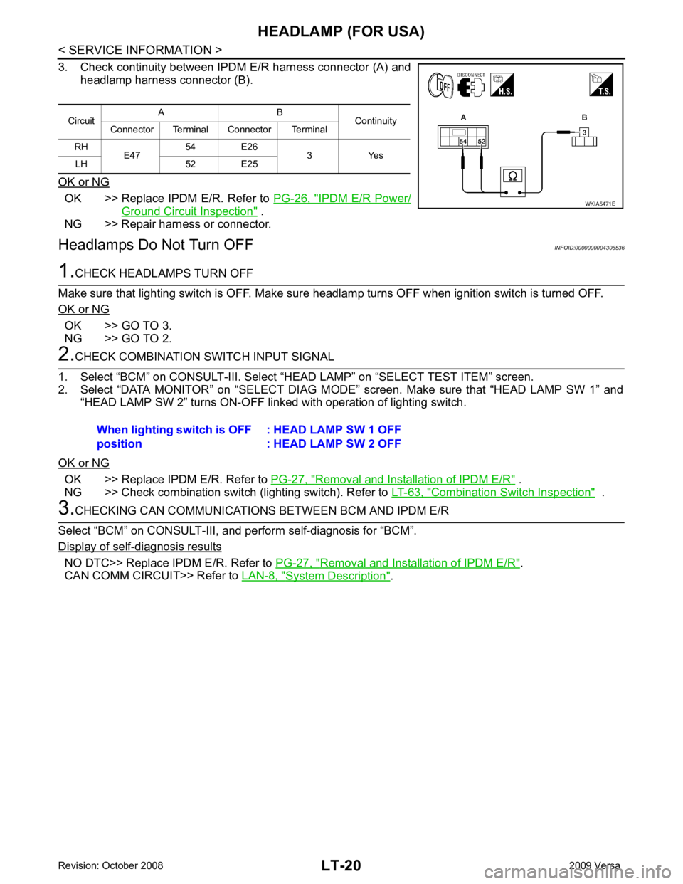
3. Check continuity between IPDM E/R harness connector (A) and
headlamp harness connector (B).
OK or NG OK >> Replace IPDM E/R. Refer to
PG-26, " IPDM E/R Power/
Ground Circuit Inspection " .
NG >> Repair harness or connector.
Headlamps Do Not Turn OFF INFOID:00000000043065361.
CHECK HEADLAMPS TURN OFF
Make sure that lighting switch is OFF. Make sure headlamp turns OFF when ignition switch is turned OFF.
OK or NG OK >> GO TO 3.
NG >> GO TO 2. 2.
CHECK COMBINATION SWITCH INPUT SIGNAL
1. Select “BCM” on CONSULT-III. Select “HEAD LAMP” on “SELECT TEST ITEM” screen.
2. Select “DATA MONITOR” on “SELECT DIAG MODE” screen. Make sure that “HEAD LAMP SW 1” and
“HEAD LAMP SW 2” turns ON-OFF linked with operation of lighting switch.
OK or NG OK >> Replace IPDM E/R. Refer to
PG-27, " Removal and Installation of IPDM E/R " .
NG >> Check combination switch (lighting switch). Refer to LT-63, " Combination Switch Inspection " .
3.
CHECKING CAN COMMUNICATIONS BETWEEN BCM AND IPDM E/R
Select “BCM” on CONSULT-III, and perform self-diagnosis for “BCM”.
Display of self - diagnosis results
NO DTC>> Replace IPDM E/R. Refer to
PG-27, " Removal and Installation of IPDM E/R " .
CAN COMM CIRCUIT>> Refer to LAN-8, " System Description " .
Circuit
A B
Continuity
Connector Terminal Connector Terminal
RH E47 54 E26
3 Yes
LH 52 E25 WKIA5471E
When lighting switch is OFF
position : HEAD LAMP SW 1 OFF
: HEAD LAMP SW 2 OFF
Page 3707 of 4331
LT
N
O P
3. Perform the preliminary check. Refer to
LT-101, " Preliminary Check " .
4. Check symptom and repair or replace the cause of the malfunction.
5. Does the interior room lamp operate norma lly? If YES, GO TO 6. If NO, GO TO 4.
6. Inspection End
Preliminary Check INFOID:0000000004306634
CHECK POWER SUPPLY AND GROUND CIRCUIT FOR BCM Refer to BCS-15, " BCM Power Supply and Ground Circuit Inspection " .
CHECK POWER SUPPLY AND GROUND CIRCUIT FOR IPDM E/R Refer to LT-11, " Preliminary Check " .
CONSULT-III Function (BCM) INFOID:0000000004306635
Refer to LT-11, " CONSULT-III Function (BCM) " .
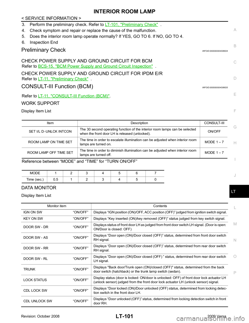
WORK SUPPORT
Display Item List
Reference between “MODE” and “TIME” for “TURN ON/OFF”
DATA MONITOR
Display Item List Item Description CONSULT-III
SET I/L D −UNLCK INTCON The 30 second operating function of the interior room lamps can be selected
when the front door LH is released (unlocked). ON/OFF
ROOM LAMP ON TIME SET The time in order to escalate illumination can be adjusted when interior room
lamps are turned on. MODE 1 – 7
ROOM LAMP OFF TIME SET The time in order to diminish illumination can be adjusted when interior room
lamps are turned off. MODE 1 – 7
MODE 1 2 3 4 5 6 7
Time (sec.) 0.5 1 2 3 4 5 0 Monitor item Contents
IGN ON SW “ON/OFF” Displays “IGN position (ON)/OFF, ACC position (OFF)” judged from ignition switch signal.
KEY ON SW “ON/OFF” Displays “Key inse rted (ON)/key removed (OFF)” status judged from key switch signal.
DOOR SW - DR “ON/OFF” Displays status of front door LH as judged from front door switch LH signal. (Door is open:
ON/Door is closed: OFF)
DOOR SW - AS “ON/OFF” Displays “Door open (ON)/Door closed (OFF)” status, determined from front door switch
RH signal.
DOOR SW - RR “ON/OFF” Displays “Door open (ON)/Door closed (OFF)” status, determined from rear door switch
RH signal.
DOOR SW - RL “ON/OFF” Displays “Door open (ON)/Door closed (OFF) ” status, determined from rear door switch
LH signal.
TRUNK “ON/OFF” Displays "Back door/Trunk open (ON)/closed (OFF)" status, determined from the back
door switch (hatchback) or the trunk lamp switch (sedan).
LOCK STATUS “ON/OFF” Display status (door is locked: ON/door is unlocked: OFF) of front door lock actuator LH
(unlock sensor) judged from the front door lock actuator LH (unlock sensor) signal.
CDL LOCK SW “ON/OFF” Displays “Door locked (ON)/Door unlocked (OFF) status, determined from locking detec-
tion switch in the front door LH.
CDL UNLOCK SW “ON/OFF” Displays “Door unlocked (OFF)” status, determined from locking detection switch in front
door RH.
Page 3894 of 4331
MTC
N
O P
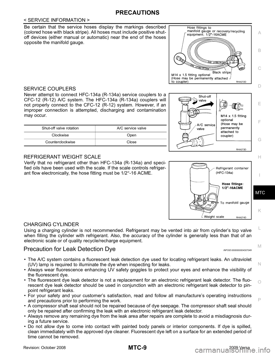
Be certain that the service hoses display the markings described
(colored hose with black stripe). All hoses must include positive shut-
off devices (either manual or aut omatic) near the end of the hoses
opposite the manifold gauge.
SERVICE COUPLERS Never attempt to connect HFC-134a (R-134a) service couplers to a
CFC-12 (R-12) A/C system. T he HFC-134a (R-134a) couplers will
not properly connect to the CFC-12 (R-12) system. However, if an
improper connection is attempted, discharging and contamination
may occur.
REFRIGERANT WEIGHT SCALE Verify that no refrigerant other than HFC-134a (R-134a) and speci-
fied oils have been used with the scale. If the scale controls refriger-
ant flow electronically, the hose fitting must be 1/2 ″-16 ACME.
CHARGING CYLINDER Using a charging cylinder is not re commended. Refrigerant may be vented into air from cylinder’s top valve
when filling the cylinder with refrigerant. Also, the accura cy of the cylinder is generally less than that of an
electronic scale or of quality recycle/recharge equipment.
Precaution for Leak Detection Dye INFOID:0000000004307049
• The A/C system contains a fluorescent leak detection dy e used for locating refrigerant leaks. An ultraviolet
(UV) lamp is required to illuminate the dye when inspecting for leaks.
• Always wear fluorescence enhancing UV safety goggles to protect your eyes and enhance the visibility of
the fluorescent dye.
• The fluorescent dye leak detector is not a replacement for an electronic refrigerant leak detector. The fluo-
rescent dye leak detector should be used in conjunction with an electronic refrigerant leak detector to pin-
point refrigerant leaks.
• For your safety and your customer’s satisfaction, read and follow all manufacture’s operating instructions
and precautions prior to performing the work.
• A compressor shaft seal should not be repaired because of dye seepage. The compressor shaft seal should
only be repaired after confirming the leak with an electronic refrigerant leak detector.
• Always remove any remaining dye from the leak area after repairs are complete to avoid a misdiagnosis dur- ing a future service.
• Do not allow dye to come into contact with paint ed body panels or interior components. If dye is spilled,
clean immediately with the approved dye cleaner. Fluores cent dye left on a surface for an extended period of
time cannot be removed. RHA274D
Page 3907 of 4331
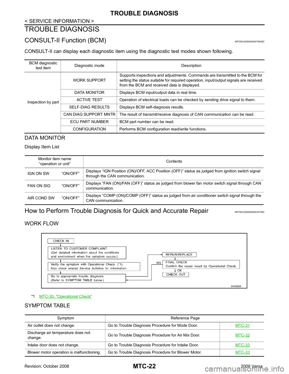
Monitor item name
“operation or unit” Contents
IGN ON SW “ON/OFF” Displays “IGN Position (ON)/OFF, ACC Position (OFF)” status as judged from ignition switch signal
through the CAN communication.
FAN ON SIG “ON/OFF” Displays “FAN (ON)/FAN (OFF)” status as judged from blower fan motor switch signal through CAN
communication.
AIR COND SW “ON/OFF” Displays “COMP (ON)/COMP (OFF)” status as judged from air conditioner switch signal through the
CAN communication. *1
MTC-30, " Operational Check "
Discharge air temperature does not
change. Go to Trouble Diagnosis Procedure for Air Mix Door.
MTC-32Intake door does not change. Go to Trouble Diagnosis Procedure for Intake Door.
MTC-33Blower motor operation is malfunctioning. Go to Trouble Diagnosis Procedure for Blower Motor.
MTC-33
Page 3974 of 4331
MTC
N
O P
Check all around the service valves. Ensure service valve caps are secured on the service valves (to
prevent leaks).
NOTE:
After removing A/C manifold gauge set from service va lves, wipe any residue from valves to prevent any
false readings by leak detector.
• Cooling unit (Evaporator)
With engine OFF, turn blower fan on “High” for at least 15 seconds to dissipate any refrigerant trace in
the cooling unit. Wait a minimum of 10 minutes ac cumulation time (refer to the manufacturer’s recom-
mended procedure for actual wait time) before inserting the leak detector probe into the drain hose.
Keep the probe inserted for at least 10 seconds. Use c aution not to contaminate the probe tip with water
or dirt that may be in the drain hose.
5. If a leak detector detects a leak, verify at least once by blowing compressed air into area of suspected
leak, then repeat check as outlined above.
6. Do not stop when one leak is found. Continue to check for additional leaks at all system components.
If no leaks are found, perform steps 7-10.
7. Start engine.
8. Set the heater A/C control as follows;
a. A/C switch: ON
b. Mode control dial position: VENT (Ventilation)
c. Intake door lever position: Recirculation
d. Max. cold temperature
e. Fan speed: High
9. Run engine at 1,500 rpm for at least 2 minutes.
10. Turn engine off and perform leak check again following steps 4 through 6 above.
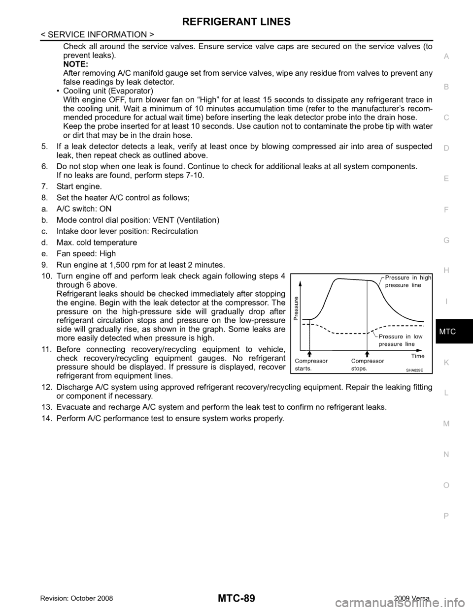
Refrigerant leaks should be chec ked immediately after stopping
the engine. Begin with the leak detector at the compressor. The
pressure on the high-pressure side will gradually drop after
refrigerant circulation stops and pressure on the low-pressure
side will gradually rise, as shown in the graph. Some leaks are
more easily detected when pressure is high.
11. Before connecting recovery/recycling equipment to vehicle, check recovery/recycling equipment gauges. No refrigerant
pressure should be displayed. If pressure is displayed, recover
refrigerant from equipment lines.
12. Discharge A/C system using approved refrigerant reco very/recycling equipment. Repair the leaking fitting
or component if necessary.
13. Evacuate and recharge A/C system and perform the l eak test to confirm no refrigerant leaks.
14. Perform A/C performance test to ensure system works properly.