Page 4000 of 4331

PG
N
O P
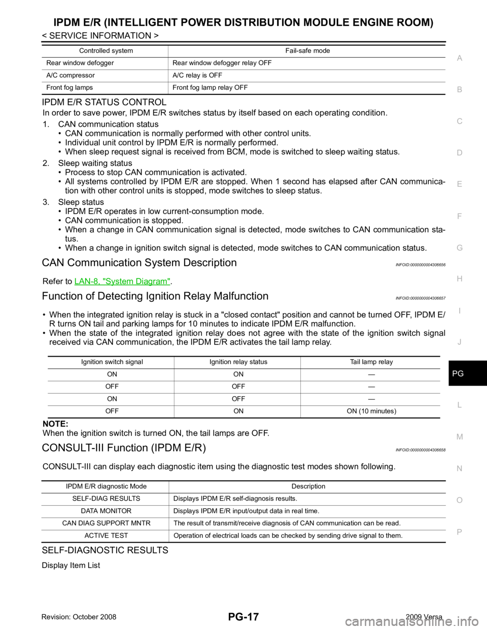
IPDM E/R STATUS CONTROL
In order to save power, IPDM E/R switches status by itself based on each operating condition.
1. CAN communication status • CAN communication is normally performed with other control units.
• Individual unit control by IPDM E/R is normally performed.
• When sleep request signal is received from BCM, mode is switched to sleep waiting status.
2. Sleep waiting status • Process to stop CAN communication is activated.
• All systems controlled by IPDM E/R are stopped. When 1 second has elapsed after CAN communica-
tion with other control units is st opped, mode switches to sleep status.
3. Sleep status • IPDM E/R operates in low current-consumption mode.
• CAN communication is stopped.
• When a change in CAN communication signal is detec ted, mode switches to CAN communication sta-
tus.
• When a change in ignition switch signal is detect ed, mode switches to CAN communication status.
CAN Communication System Description INFOID:0000000004306656
Refer to LAN-8, " System Diagram " .
Function of Detecting Ig nition Relay Malfunction INFOID:0000000004306657
• When the integrated ignition relay is stuck in a "clo sed contact" position and cannot be turned OFF, IPDM E/
R turns ON tail and parking lamps for 10 mi nutes to indicate IPDM E/R malfunction.
• When the state of the integrated ignition relay does not agree with the state of the ignition switch signal
received via CAN communication, the IPDM E/R activates the tail lamp relay.
NOTE:
When the ignition switch is turned ON, the tail lamps are OFF.
CONSULT-III Function (IPDM E/R) INFOID:0000000004306658
CONSULT-III can display each diagnostic item using the diagnostic test modes shown following.
SELF-DIAGNOSTIC RESULTS
Display Item List Rear window defogger Rear window defogger relay OFF
A/C compressor A/C relay is OFF
Front fog lamps Front fog lamp relay OFF Controlled system Fail-safe mode Ignition switch signal Ignition relay status Tail lamp relay
ON ON —
OFF OFF — ON OFF —
OFF ON ON (10 minutes) IPDM E/R diagnostic Mode Description
SELF-DIAG RESULTS Displays IPDM E/R self-diagnosis results.
DATA MONITOR Displays IPDM E/R input/output data in real time.
CAN DIAG SUPPORT MNTR The result of transmit/receive diagnosis of CAN communication can be read. ACTIVE TEST Operation of electrical loads can be checked by sending drive signal to them.
Page 4001 of 4331

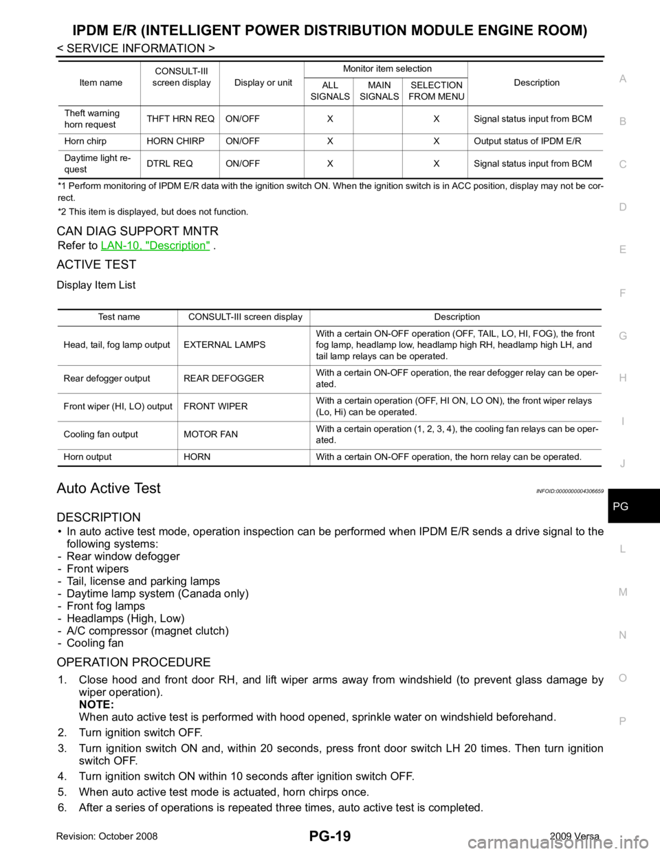
Item name
CONSULT-III
screen display Display or unit Monitor item selection
Description
ALL
SIGNALS MAIN
SIGNALS SELECTION
FROM MENU
Motor fan request MOTOR FAN
REQ 1/2/3/4 X X X Signal status input from ECM
Compressor re-
quest AC COMP REQ ON/OFF X X X Signal status input from ECM
Parking, license,
and tail lamp re-
quest TAIL & CLR REQ ON/OFF X X X Signal status input from BCM
Headlamp low
beam request HL LO REQ ON/OFF X X X Signal status input from BCM
Headlamp high
beam request HL HI REQ ON/OFF X X X Signal
status input from BCM
Front fog request FR FOG REQ ON/OFF X X X Signal status input from BCM
FR wiper request FR WIP REQ STOP/1LO/LO/HI X X X Signal status input from BCM
Wiper auto stop WIP AUTO
STOP ACT P/STOP P X X X Output status of IPDM E/R
Wiper protection WIP PROT OFF/LS/HS/Block X X X Control status of IPDM E/R
Starter request ST RLY REQ ON/OFF X X Status of input signal (*1)
Ignition relay
status IGN RLY ON/OFF X X X Ignition relay status monitored
with IPDM E/R
Rear defogger re-
quest RR DEF REQ ON/OFF X X X Signal status input from BCM
Oil pressure
switch OIL P SW OPEN/CLOSE X X
Signal status input from IPDM
E/R
Hood switch HOOD SW (*2) OFF X X Signal status input from IPDM
E/R
Page 4002 of 4331

PG
N
O P
*1 Perform monitoring of IPDM E/R data with the ignition switch ON. When the ignition switch is in ACC position, display may no
t be cor-
rect.
*2 This item is displayed, but does not function.
CAN DIAG SUPPORT MNTR Refer to LAN-10, " Description " .
ACTIVE TEST
Display Item List
Auto Active Test INFOID:0000000004306659
DESCRIPTION • In auto active test mode, operation inspection can be performed when IPDM E/R sends a drive signal to the
following systems:
- Rear window defogger
- Front wipers
- Tail, license and parking lamps
- Daytime lamp system (Canada only)
- Front fog lamps
- Headlamps (High, Low)
- A/C compressor (magnet clutch)
- Cooling fan
OPERATION PROCEDURE 1. Close hood and front door RH, and lift wiper arms away from windshield (to prevent glass damage by
wiper operation).
NOTE:
When auto active test is performed with hood opened, sprinkle water on windshield beforehand.
2. Turn ignition switch OFF.
3. Turn ignition switch ON and, within 20 seconds, pre ss front door switch LH 20 times. Then turn ignition
switch OFF.
4. Turn ignition switch ON within 10 seconds after ignition switch OFF.
5. When auto active test mode is actuated, horn chirps once.
6. After a series of operations is repeated th ree times, auto active test is completed.
Theft warning
horn request THFT HRN REQ ON/OFF X X Signal status input from BCM
Horn chirp HORN CHIRP ON/OFF X X O utput status of IPDM E/R
Daytime light re-
quest DTRL REQ ON/OFF X X Signal
status input from BCM
Item name
CONSULT-III
screen display Display or unit Monitor item selection
Description
ALL
SIGNALS MAIN
SIGNALS SELECTION
FROM MENU Test name CONSULT-III screen display Description
Head, tail, fog lamp output EXTERNAL LAMPS With a certain ON-OFF operation (OFF, TAIL, LO, HI, FOG), the front
fog lamp, headlamp low, headlamp high RH, headlamp high LH, and
tail lamp relays can be operated.
Rear defogger output REAR DEFOGGER With a certain ON-OFF operation, the rear defogger relay can be oper-
ated.
Front wiper (HI, LO) output FRONT WIPER With a certain operation (OFF, HI ON, LO ON), the front wiper relays
(Lo, Hi) can be operated.
Cooling fan output MOTOR FAN With a certain operation (1, 2, 3, 4), the cooling fan relays can be oper-
ated.
Horn output HORN With a certain ON-OFF operation, the horn relay can be operated.
Page 4097 of 4331

System Description " .
3. According to the trouble diagnosis chart, repa ir or replace the cause of the malfunction.
Refer to RF-17, " Trouble Diagnosis Chart by Symptom " .
4. Does sunroof system operate normally? If Yes, GO TO 5. If No, GO TO 3.
5. Inspection End.
CONSULT-III Function (BCM) INFOID:0000000004307400
CONSULT-III can display each diagnostic item us ing the diagnostic test modes shown following.
Terminal
Wire col-
or Item Condition
Voltage
(Approx.)
1 R Sunroof switch (UP/CLOSE) signal Ignition switch ON and sunroof
switch in UP/CLOSE position 0
Ignition switch ON and sunroof
switch in OFF position Battery voltage
5 G Sunroof switch (DOWN/OPEN) signal Ignition switch ON and sunroof
switch in DOWN/OPEN position 0
Ignition switch ON and sunroof
switch in OFF position Battery voltage
7 P BAT power supply — Battery voltage
8 O Vehicle speed signal Speedometer operated [when ve-
hicle speed is approx. 40 km/h (25 MPH)]
9 W RAP signal Ignition switch ON Battery voltage
Within 45 seconds after ignition switch is turned OFF Battery voltage
When front door LH or RH is
opened while retained power is
operating 0
10 B Ground — 0
Page 4117 of 4331

.
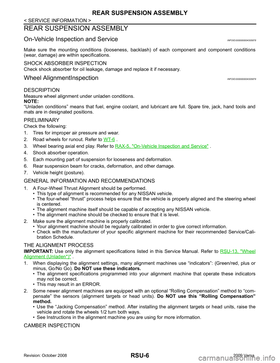
3. Wheel bearing axial end play. Refer to RAX-5, " On-Vehicle Inspection and Service " .
4. Shock absorber operation.
5. Each mounting part of suspension for looseness and deformation.
6. Rear suspension beam for cracks, deformation, and other damage.
7. Vehicle height (posture).
GENERAL INFORMATION AND RECOMMENDATIONS
1. A Four-Wheel Thrust Alignment should be performed. • This type of alignment is recommended for any NISSAN vehicle.
• The four-wheel “thrust” process helps ensure that the vehicle is properly aligned and the steering wheel
is centered.
• The alignment machine itself should be ca pable of accepting any NISSAN vehicle.
• The alignment machine should be checked to ensure that it is level.
2. Make sure the alignment machine is properly calibrated. • Your alignment machine should be regularly calibrated in order to give correct information.
• Check with the manufacturer of your specific al ignment machine for their recommended Service/Cali-
bration Schedule.
THE ALIGNMENT PROCESS
IMPORTANT: Use only the alignment specifications listed in this Service Manual. Refer to RSU-13, " Wheel
Alignment (Unladen*) " .
1. When displaying the alignment settings, many alignm ent machines use “indicators”: (Green/red, plus or
minus, Go/No Go). Do NOT use these indicators.
• The alignment specifications programmed into your alignment machine that operate these indicators
may not be correct.
• This may result in an ERROR.
2. Some newer alignment machines are equipped with an optional “Rolling Compensation” method to “com- pensate” the sensors (alignment targets or head units). Do NOT use this “Rolling Compensation”
method.
• Use the “Jacking Compensation” method. After inst alling the alignment targets or head units, raise the
vehicle and rotate the wheels 1/2 turn both ways.
• See Instructions in the alignment machine you are using for more information.
CAMBER INSPECTION
Page 4198 of 4331
How to Handle Battery " .)
• Fuses (Refer to SRS-11, " Schematic " .)
• System component-to-harness connections
WORK FLOW User mode Diagnosis mode Display type
“AIR BAG” warning lamp X X ON-OFF operation CONSULT-III — X Monitoring
Page 4207 of 4331
SRS
N
O P
CONSULT-III Function (AIR BAG)
INFOID:0000000004307187
CONSULT-III can display each diagnostic item using the diagnostic test modes shown following.
Page 4214 of 4331
![NISSAN LATIO 2009 Service Repair Manual SRS Operation Check " .
DIAGNOSTIC PROCEDURE 4
Check SRS Repair History Yes >> Self-diagnostic result “SELF-DIAG [PAST]” (pre
viously stored in the memory) might not be erased
after repair. Go to NISSAN LATIO 2009 Service Repair Manual SRS Operation Check " .
DIAGNOSTIC PROCEDURE 4
Check SRS Repair History Yes >> Self-diagnostic result “SELF-DIAG [PAST]” (pre
viously stored in the memory) might not be erased
after repair. Go to](/manual-img/5/57359/w960_57359-4213.png)
SRS Operation Check " .
DIAGNOSTIC PROCEDURE 4
Check SRS Repair History Yes >> Self-diagnostic result “SELF-DIAG [PAST]” (pre
viously stored in the memory) might not be erased
after repair. Go to "DIAGNOSTIC PROCEDURE 3".
No >> Go to "DIAGNOSTIC PROCEDURE 2".
DIAGNOSTIC PROCEDURE 5
Check SRS Intermittent Malfuncti on Using CONSULT-III—Diagnosis Mode
1. If diagnostic codes are displayed on “SELF-DIAG [PAST]”, go to step 4. If no malfunction is detected on “SELF-DIAG [PAS T]”, touch “BACK” and go back to “SELECT DIAG
MODE”.
PASS A/B INDCTR CKT
[B1023] Front passenger air bag off indicator is malfunctioning. 1. Visually check the wiring harness
connection.
2. Replace the harness if it has visi- ble damage.
3. Replace front passenger air bag off indicator.
4. Replace the air bag diagnosis
sensor unit.
5. Replace the related harness.
FRONTAL COLLISION DETECTION
[B1209] Driver and front passenger air bag modules are deployed. Refer to
SRS-47 .
SIDE COLLISION DETECTION [B1210] Side or curtain air bag modules are deployed.
Diagnostic item Explanation
Repair order
Recheck SRS at each replacement