Page 3829 of 4331
MT
N
O P
39. Shift control shaft shift lever (1) to the neutral position.
40. Install O-ring to rear housing.
41. Install rear housing to transaxle case, and tighten bolts ( ) to the specified torque. Refer to MT-16, " Exploded View " .
CAUTION:
Never pinch O-ring when installing rear housing.
42. Install drain plug according to the following procedures.
a. Install gasket to drain plug. CAUTION:
Never reuse gasket.
b. Install drain plug to clutch housing using a suitable tool.
c. Tighten drain plug to the specified torque. Refer to MT-16," Exploded View " .
43. Install filler plug according to the following procedures.
a. Install gasket to filler plug, and then install them to transaxle case. CAUTION:
Never reuse gasket.
b. Tighten filler plug to the specified torque. Refer to MT-16, " Exploded View " .
CAUTION:
Fill with gear oil before tightening filler plug to the specified torque.
Page 3838 of 4331
![NISSAN LATIO 2009 Service Repair Manual MT-44< SERVICE INFORMATION >
[RS6F94R]
PRECAUTIONS
SERVICE INFORMATION
PRECAUTIONS
Precaution for Supplemental Restraint Syst em (SRS) "AIR BAG" and "SEAT BELT
PRE-TENSIONER" INFOID:0000000004305264
NISSAN LATIO 2009 Service Repair Manual MT-44< SERVICE INFORMATION >
[RS6F94R]
PRECAUTIONS
SERVICE INFORMATION
PRECAUTIONS
Precaution for Supplemental Restraint Syst em (SRS) "AIR BAG" and "SEAT BELT
PRE-TENSIONER" INFOID:0000000004305264](/manual-img/5/57359/w960_57359-3837.png)
MT-44< SERVICE INFORMATION >
[RS6F94R]
PRECAUTIONS
SERVICE INFORMATION
PRECAUTIONS
Precaution for Supplemental Restraint Syst em (SRS) "AIR BAG" and "SEAT BELT
PRE-TENSIONER" INFOID:0000000004305264
The Supplemental Restraint System such as “A IR BAG” and “SEAT BELT PRE-TENSIONER”, used along
with a front seat belt, helps to reduce the risk or severi ty of injury to the driver and front passenger for certain
types of collision. This system includes seat belt switch inputs and dual stage front air bag modules. The SRS
system uses the seat belt switches to determine the front air bag deployment, and may only deploy one front
air bag, depending on the severity of a collision and w hether the front occupants are belted or unbelted.
Information necessary to service the system safely is included in the SRS and SB section of this Service Man-
ual.
WARNING:
• To avoid rendering the SRS inopera tive, which could increase the risk of personal injury or death in
the event of a collision which would result in air bag inflation, all maintenance must be performed by
an authorized NISS AN/INFINITI dealer.
• Improper maintenance, including in correct removal and installation of the SRS, can lead to personal
injury caused by unintent ional activation of the system. For re moval of Spiral Cable and Air Bag
Module, see the SRS section.
• Do not use electrical test equipmen t on any circuit related to the SRS unless instructed to in this
Service Manual. SRS wiring harn esses can be identified by yellow and/or orange harnesses or har-
ness connectors.
Precaution for Procedure without Cowl Top Cover INFOID:0000000004305265
When performing the procedure after removing cowl top cover, cover
the lower end of windshield with urethane, etc.
Precaution INFOID:0000000004305266
• If transaxle assembly is removed from the vehi cle, always replace CSC (Concentric Slave Cylinder).
Installed CSC returns to the original position when removing transaxle assembly. Dust on clutch disc sliding
parts may damage CSC seal, and may cause clutch fluid leakage.
• Do not reuse transaxle oil.
• Drain, fill and check transaxle oil with the vehicle on level surface.
• During removal or installation, keep inside of transaxle clear of dust or dirt.
• Check for the correct installation orientation prior to removal or disassembly. If matching marks are required,
be certain they do not interfere with the f unction of the parts they are applied to.
• In principle, tighten bolts or nuts gradually in several steps working diagonally from inside to outside. If tight-
ening sequence is specified, follow it.
• Be careful not to damage the sliding surfaces and mating surfaces of parts. PIIB3706J
Page 3839 of 4331

MT
N
O P
PREPARATION
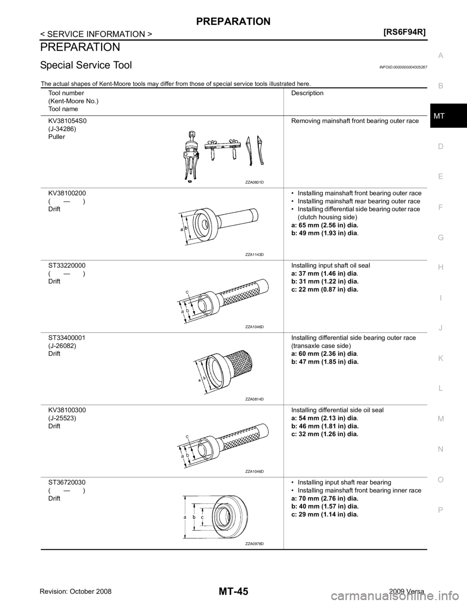
Special Service Tool INFOID:0000000004305267
The actual shapes of Kent-Moore tools may differ fr om those of special service tools illustrated here.
Tool number
(Kent-Moore No.)
Tool name Description
KV381054S0
(J-34286)
Puller Removing mainshaft front bearing outer race
KV38100200
( — )
Drift • Installing mainshaft front bearing outer race
• Installing mainshaft rear bearing outer race
• Installing differential side bearing outer race
(clutch housing side)
a: 65 mm (2.56 in) dia.
b: 49 mm (1.93 in) dia .
ST33220000
( — )
Drift Installing input shaft oil seal
a: 37 mm (1.46 in) dia .
b: 31 mm (1.22 in) dia.
c: 22 mm (0.87 in) dia.
ST33400001
(J-26082)
Drift Installing differential side bearing outer race
(transaxle case side)
a: 60 mm (2.36 in) dia .
b: 47 mm (1.85 in) dia.
KV38100300
(J-25523)
Drift Installing differential side oil seal
a: 54 mm (2.13 in) dia .
b: 46 mm (1.81 in) dia.
c: 32 mm (1.26 in) dia.
ST36720030
( — )
Drift • Installing input shaft rear bearing
• Installing mainshaft front bearing inner race
a: 70 mm (2.76 in) dia.
b: 40 mm (1.57 in) dia.
c: 29 mm (1.14 in) dia. ZZA1143D
ZZA1046D
ZZA1046D
ZZA0978D
Page 3842 of 4331
![NISSAN LATIO 2009 Service Repair Manual MT-48< SERVICE INFORMATION >
[RS6F94R]
PREPARATION
Drift Installing differential side bearing inner race
(clutch housing side)
a: 45 mm (1.77 in) dia.
b: 39 mm (1.54 in) dia .
Drift Installing differ NISSAN LATIO 2009 Service Repair Manual MT-48< SERVICE INFORMATION >
[RS6F94R]
PREPARATION
Drift Installing differential side bearing inner race
(clutch housing side)
a: 45 mm (1.77 in) dia.
b: 39 mm (1.54 in) dia .
Drift Installing differ](/manual-img/5/57359/w960_57359-3841.png)
MT-48< SERVICE INFORMATION >
[RS6F94R]
PREPARATION
Drift Installing differential side bearing inner race
(clutch housing side)
a: 45 mm (1.77 in) dia.
b: 39 mm (1.54 in) dia .
Drift Installing differential side bearing inner race
(transaxle case side)
a: 52 mm (2.05 in) dia.
b: 45 mm (1.77 in) dia.
Puller Removing differential side bearing inner race
(clutch housing side)
Removing differential side bearing inner race
(transaxle case side)
Puller • Removing differential side bearing inner
race (clutch housing side)
• Removing differential side bearing inner
race (transaxle case side)
• Removing input shaft rear bearing
• Removing input shaft front bearing
• Removing mainshaft rear bearing inner race
• Removing 6th main gear
• Removing 4th main gear
• Removing 5th main gear
• Removing 1st main gear
• Removing 1st - 2nd synchronizer hub as-
sembly
• Removing 2nd main gear
• Removing 3rd main gear
• Removing mainshaft front bearing outer race
Remover • Removing bushing
• Removing mainshaft rear bearing outer
race
Power tool • Loosening bolts and nuts
Tool name
Description S-NT474
S-NT474
NT077
ZZB0823D
S-NT134
PBIC0190E
Page 3847 of 4331
MT
N
O P
SIDE OIL SEAL
Removal and Installation INFOID:0000000004305273
REMOVAL 1. Remove front drive shafts from transaxle assembly. Refer to FAX-9, " Removal and Installation (Left
Side) " .
2. Remove differential side oil seal (1) using a suitable tool.
CAUTION:
Be careful not to damage transaxle case and clutch housing.
INSTALLATION Installation is in the reverse order of removal.
• Install differential side oil seals (1) to clutch housing and transaxle case using Tool (A).
• B: Transaxle case side
• C: Clutch housing side
CAUTION:
• Never reuse differential side oil seal.
• When installing, never inclin e differential side oil seal.
• Never damage clutch housing and transaxle case.
Check oil level and oil leakage after installation. Refer to MT-52," Checking M/T Oil " .
Page 3849 of 4331
MT
N
O P
CONTROL LINKAGE
Component of Contro l Device and Cable INFOID:0000000004305275
Removal and Installation INFOID:0000000004305276
REMOVAL 1. Remove battery. Refer to SC-7, " Removal and Installation " .
2. Remove air duct (front), air duct (Inlet) and air cleaner case. Refer to EM-139, " Removal and Installation " .
3. Remove shift cable from shift lever.
4. Remove select cable according to the following.
a. Move stopper (1) to the unlocked position. 1. Control lever knob 2. Control lever 3. Control device assembly
4. Select cable 5. Shift cable 6. Lock plate
7. Clutch housing 8. Cable bracket 9. Tapping bolt
10. Cable support bracket 11. Adapter plate SCIA7842E
Page 3850 of 4331

Removal and
Installation " .
8. Remove control device assembly bolts.
9. Remove exhaust front tube, center muffler and heat plate. Refer to EX-9, " Removal and Installation " .
10. Remove cable support bracket.
11. Remove select cable and shift cable from cable bracket.
12. Remove control device assembly from the vehicle.
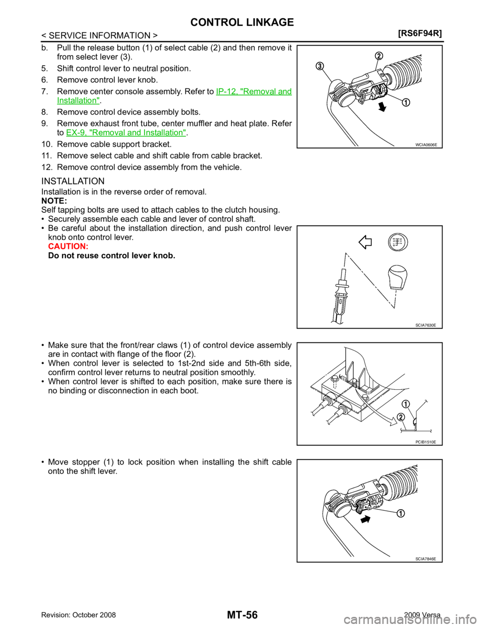
INSTALLATION
Installation is in the reverse order of removal.
NOTE:
Self tapping bolts are used to attach cables to the clutch housing.
• Securely assemble each cable and lever of control shaft.
• Be careful about the installation direction, and push control lever knob onto control lever.
CAUTION:
Do not reuse control lever knob.
• Make sure that the front/rear claws (1) of control device assembly are in contact with flange of the floor (2).
• When control lever is selected to 1st-2nd side and 5th-6th side,
confirm control lever returns to neutral position smoothly.
• When control lever is shifted to each position, make sure there is
no binding or disconnection in each boot.
• Move stopper (1) to lock position when installing the shift cable onto the shift lever. SCIA7630E
SCIA7846E
Page 3852 of 4331
Changing M/T Oil " .
2. Drain clutch fluid and remove clutch tube from CSC. Refer to CL-10, " Removal and Installation " .
CAUTION:
Do not depress clutch pedal during removal procedure.
3. Remove engine and transaxle assembly. Refer to EM-195, " Removal and Installation " .
4. Remove starter motor. Refer to SC-20, " Removal and Installation MR18DE " .
5. Remove transaxle assembly to engine bolts.
6. Separate transaxle assembly from engine.
INSTALLATION 1. LH engine mount bracket (transaxle
side) 2. Transaxle assembly 3. Rear engine mount bracket
4. Washer 5. Rear torque rod ⇐Front
: Refer to MT-58, " Removal and Installation " .