2009 NISSAN LATIO clutch
[x] Cancel search: clutchPage 3882 of 4331
![NISSAN LATIO 2009 Service Repair Manual MT-88< SERVICE INFORMATION >
[RS6F94R]
FINAL DRIVE
FINAL DRIVE
Disassembly and Assembly INFOID:0000000004305283
DISASSEMBLY
1. Remove differential side bearing inner race (clutch housing side) (1) acc NISSAN LATIO 2009 Service Repair Manual MT-88< SERVICE INFORMATION >
[RS6F94R]
FINAL DRIVE
FINAL DRIVE
Disassembly and Assembly INFOID:0000000004305283
DISASSEMBLY
1. Remove differential side bearing inner race (clutch housing side) (1) acc](/manual-img/5/57359/w960_57359-3881.png)
MT-88< SERVICE INFORMATION >
[RS6F94R]
FINAL DRIVE
FINAL DRIVE
Disassembly and Assembly INFOID:0000000004305283
DISASSEMBLY
1. Remove differential side bearing inner race (clutch housing side) (1) according to the following procedures.
a. Set a suitable toolto differential side bearing inner race (clutch housing side).
b. Remove differential side bearing inner race (clutch housing side) using Tool (A).
2. Remove speedometer drive gear.
3. Remove final gear bolts, and then remove final gear (1).
4. Remove differential side bearing inner race (transaxle case side) (1) according to the following procedures.
a. Set a suitable tool to differential side bearing inner race (tran- saxle case side).
b. Remove differential side bearing inner race (transaxle case side) using a suitable tool (A).
INSPECTION AFTER DISASSEMBLY
Gear and Case
Check final gear and differential case. Replace if necessary.
Bearing
Check bearing for damage and unsmooth rotation. Replace if neces-
sary.
CAUTION:
• Replace differential side bear ing outer race (clutch housing
side) and differential side bear ing inner race (clutch housing
side) as a set.
• Replace differential side bearing inner race (transaxle case side) and differential side bearing outer race (transaxle case
side) as a set.
ASSEMBLY Tool number A: ST33061000 (J-8107-2) PCIB1767E
JPDIC0446ZZ
JPDIC0114ZZ
SPD715
Page 3883 of 4331
MT
N
O P
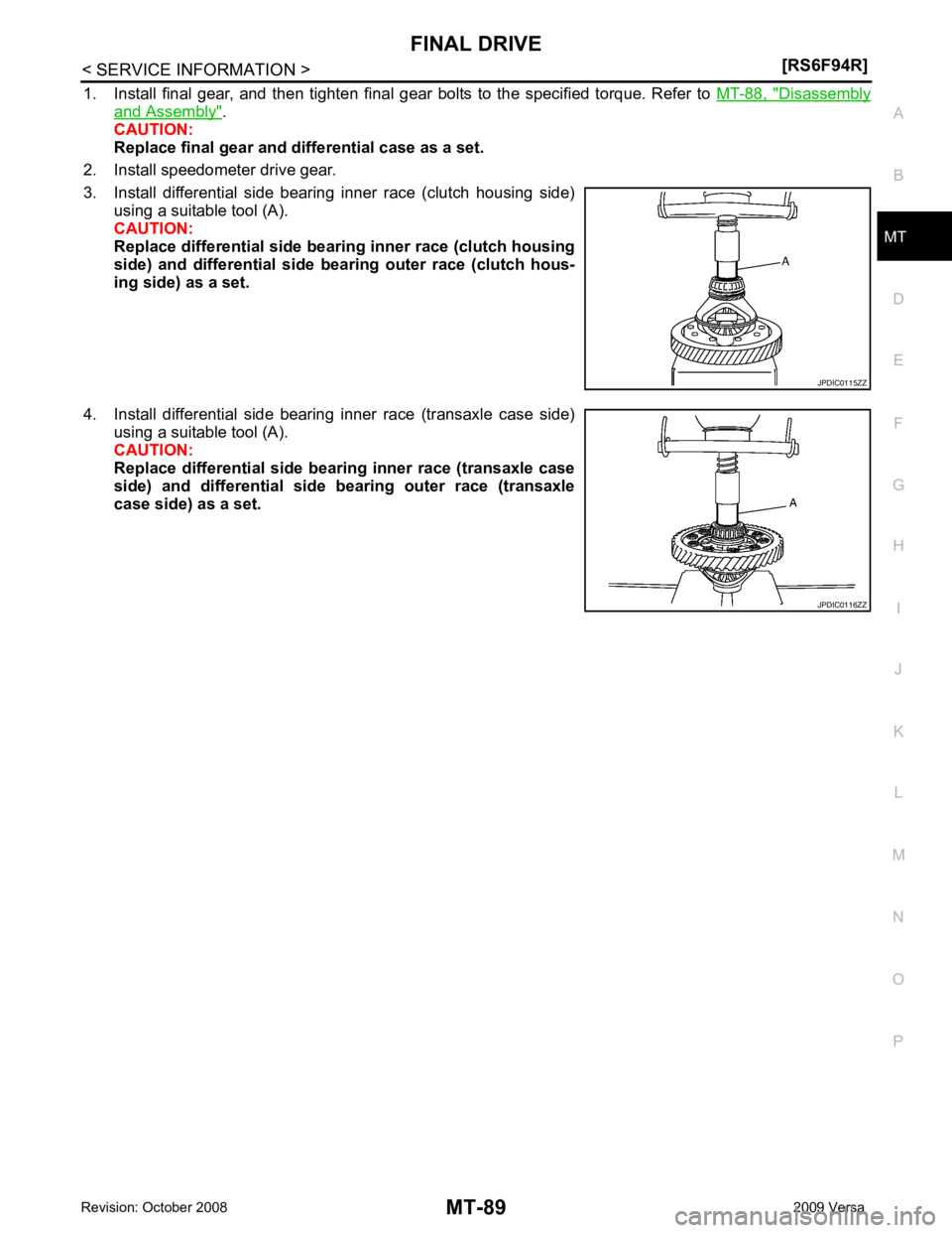
1. Install final gear, and then tighten final gear bolts to the specified torque. Refer to
MT-88, " Disassembly
and Assembly " .
CAUTION:
Replace final gear and differential case as a set.
2. Install speedometer drive gear.
3. Install differential side bearing inner race (clutch housing side) using a suitable tool (A).
CAUTION:
Replace differential side bear ing inner race (clutch housing
side) and differential side bearing outer race (clutch hous-
ing side) as a set.
4. Install differential side bearing inner race (transaxle case side) using a suitable tool (A).
CAUTION:
Replace differential side bearing inner race (transaxle case
side) and differential side bearing outer race (transaxle
case side) as a set. JPDIC0116ZZ
Page 3886 of 4331

MTC
N
O P
CONTENTS
MANUAL AIR CONDITIONER
SERVICE INFORMATION .. ..........................3
PRECAUTIONS .............................................. .....3
Precaution for Supplemental Restraint System
(SRS) "AIR BAG" and "SEAT BELT PRE-TEN-
SIONER" ............................................................. ......
3
Precaution Necessary fo r Steering Wheel Rota-
tion After Battery Disconnect ............................... ......
3
Precaution for Procedure without Cowl Top Cover ......4
Precaution for Working with HFC-134a (R-134a) ......4
General Refrigerant Precaution .......................... ......4
Oil Precaution ...................................................... ......5
Precaution for Refrigeran t Connection ......................5
Precaution for Service of Compressor ................ ......7
Precaution for Service Equipment ....................... ......8
Precaution for Leak Detection Dye ..................... ......9
PREPARATION .............................................. ....11
HFC-134a (R-134a) Service Tool and Equipment ....11
Commercial Service Tool .................................... ....13
REFRIGERATION SYSTEM .......................... ....15
Refrigerant Cycle ................................................ ....15
Refrigerant System Protec tion ................................15
Component Part Location ................................... ....16
OIL .................................................................. ....17
Maintenance of Oil Quantity in Compressor ....... ....17
AIR CONDITIONER CONTROL ..................... ....19
Control Operation ................................................ ....19
Discharge Air Flow .............................................. ....20
System Description ............................................. ....20
TROUBLE DIAGNOSIS ................................. ....22
CONSULT-II Function (BCM) .............................. ....22
How to Perform Trouble Diagnosis for Quick and
Accurate Repair ........... ...........................................
22
Component Parts and Harness Connector Loca-
tion ...................................................................... ....
23
Schematic ........................................................... ....25
Wiring Diagram - Heater - ................................... ....26 Wiring Diagram - A/C,M - ....................................
....27
Operational Check ............................................... ....30
Mode Door ........................................................... ....31
Air Mix Door ......................................................... ....32
Intake Door .......................................................... ....33
Front Blower Motor Circuit .......................................33
Magnet Clutch Circuit (If Equipped) ..................... ....37
Insufficient Cooling .............................................. ....45
Insufficient Heating .............................................. ....52
Noise ................................................................... ....53
CONTROLLER .................................................. 55
Removal and Installation ..................................... ....55
Disassembly and Assembly ................................. ....56
THERMO CONTROL AMPLIFIER .................... 57
Removal and Installation ..................................... ....57
A/C UNIT ASSEMBLY ...................................... 58
Removal and Installation ..................................... ....58
Disassembly and Assembly ................................. ....60
BLOWER MOTOR ............................................ 62
Removal and Installation ..................................... ....62
INTAKE DOOR .................................................. 63
Intake Door Cable Adjustment ............................. ....63
AIR MIX DOOR ................................................. 64
Air Mix Door Cable Adjustment ........................... ....64
MODE DOOR .................................................... 65
Mode Door Cable Adjustment ............................. ....65
BLOWER FAN RESISTOR ............................... 66
Removal and Installation ..................................... ....66
HEATER CORE ................................................. 67
Removal and Installation ..................................... ....67
AIR CONDITIONER FILTER ............................. 68
Removal and Installation ..................................... ....68
Page 3893 of 4331
Maintenance of Oil Quantity in Compressor " .
• Keep friction surfaces between clut ch and pulley clean. If the surface is contaminated, with oil, wipe
it off by using a clean waste cloth moistened with thinner.
• After compressor service operation, turn the compresso r shaft by hand more than five turns in both
directions. This will equally dist ribute oil inside the compressor. After the compressor is installed,
let the engine idle and operat e the compressor for one hour.
• After replacing the compressor magnet clutch, ap ply voltage to the new one and check for usual
operation.
Precaution for Service Equipment INFOID:0000000004307048
RECOVERY/RECYCLING EQUIPMENT
Be certain to follow the manufacturer’s instructions for machine operation and machine maintenance. Never
introduce any refrigerant other than that specified into the machine.
ELECTRONIC LEAK DETECTOR
Be certain to follow the manufacturer’s instruct ions for tester operation and tester maintenance.
VACUUM PUMP
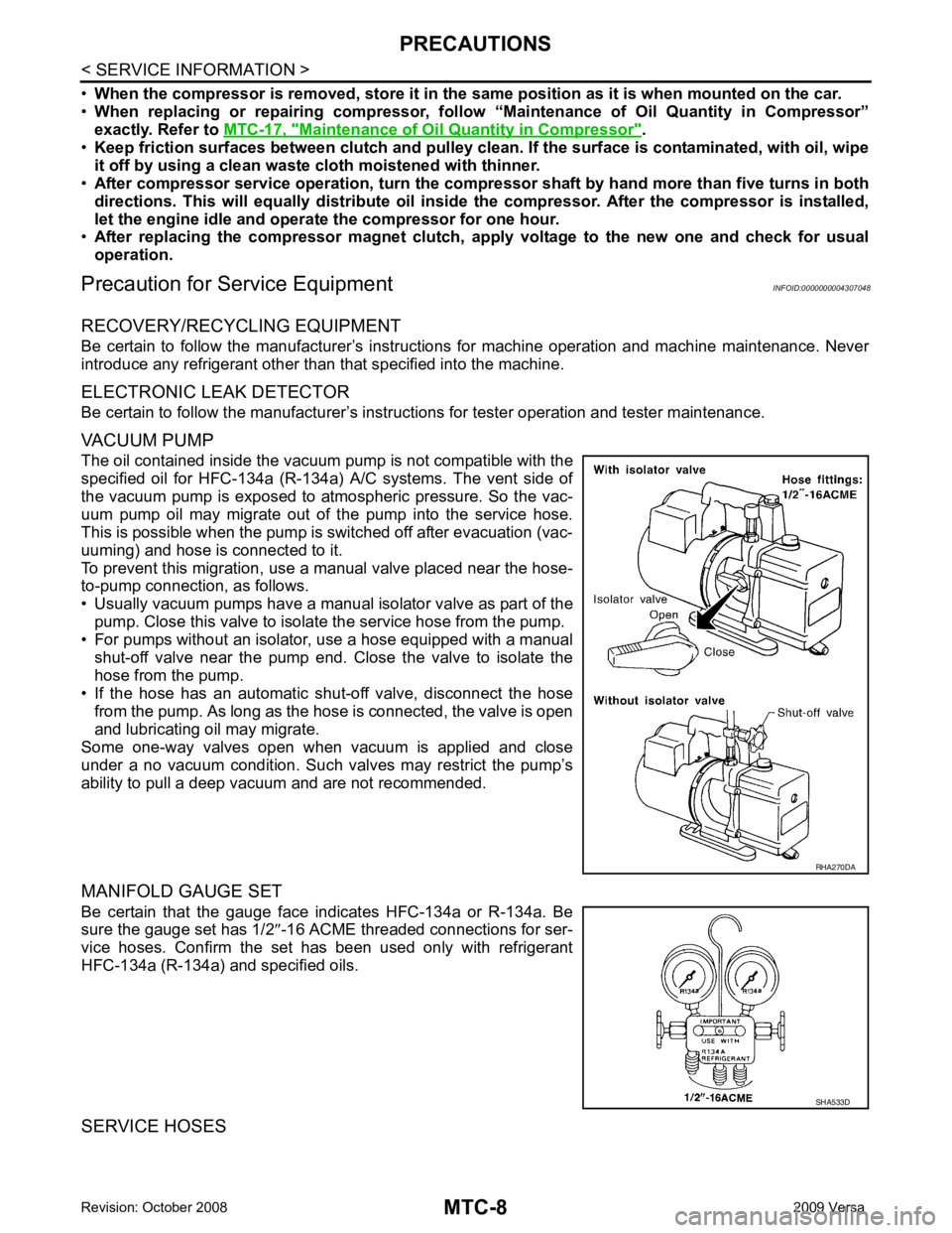
The oil contained inside the vacuum pump is not compatible with the
specified oil for HFC-134a (R-134a) A/C systems. The vent side of
the vacuum pump is exposed to atmospheric pressure. So the vac-
uum pump oil may migrate out of the pump into the service hose.
This is possible when the pump is switched off after evacuation (vac-
uuming) and hose is connected to it.
To prevent this migration, use a manual valve placed near the hose-
to-pump connection, as follows.
• Usually vacuum pumps have a manual isolator valve as part of the pump. Close this valve to isolat e the service hose from the pump.
• For pumps without an isolator, use a hose equipped with a manual
shut-off valve near the pump end. Close the valve to isolate the
hose from the pump.
• If the hose has an automatic shut -off valve, disconnect the hose
from the pump. As long as the hose is connected, the valve is open
and lubricating oil may migrate.
Some one-way valves open when vacuum is applied and close
under a no vacuum condition. Such valves may restrict the pump’s
ability to pull a deep vacuum and are not recommended.
MANIFOLD GAUGE SET
Be certain that the gauge face indicates HFC-134a or R-134a. Be
sure the gauge set has 1/2 ″-16 ACME threaded connections for ser-
vice hoses. Confirm the set has been used only with refrigerant
HFC-134a (R-134a) and specified oils.
SERVICE HOSES SHA533D
Page 3908 of 4331
MTC
N
O P
Component Parts and Har
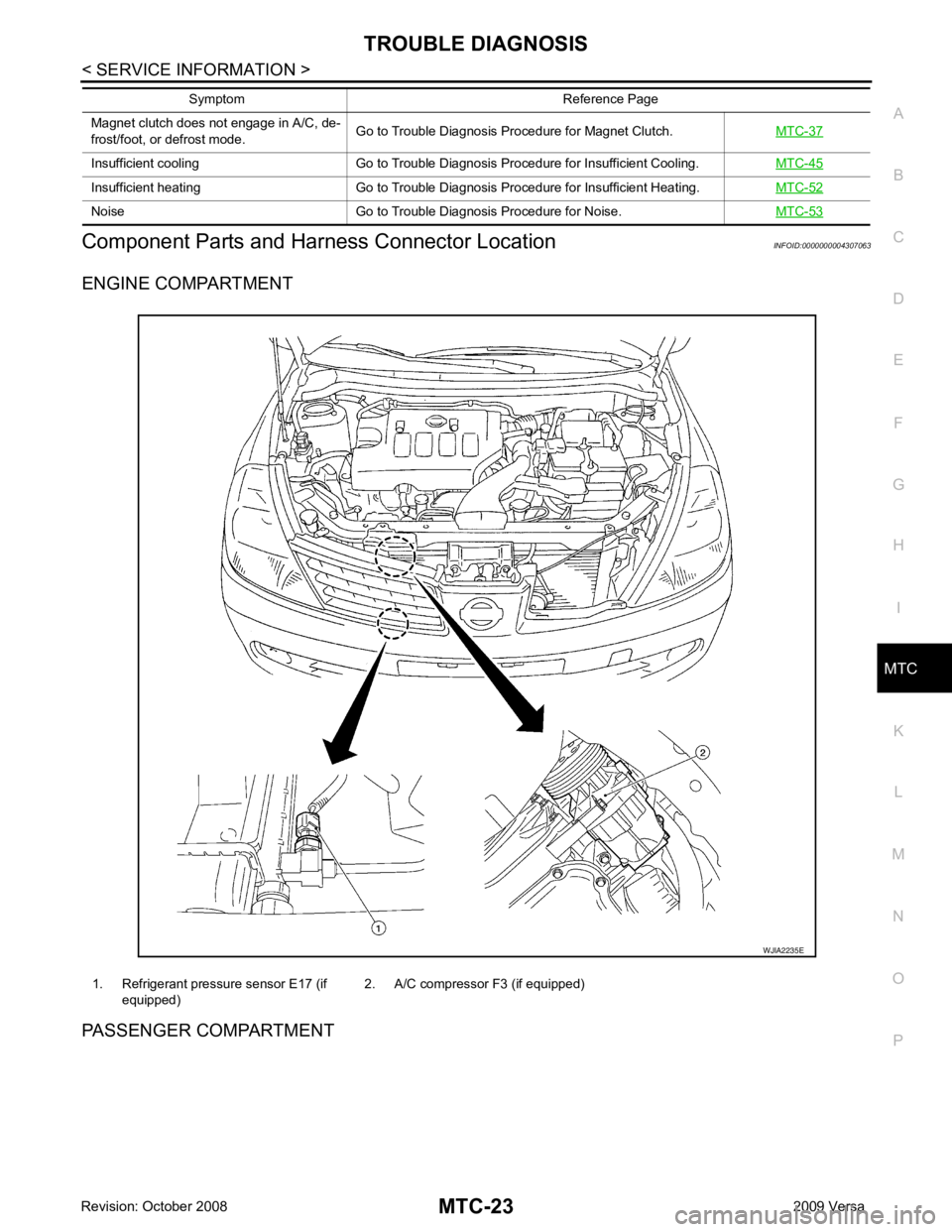
ness Connector Location INFOID:0000000004307063
ENGINE COMPARTMENT
PASSENGER COMPARTMENT Magnet clutch does not engage in A/C, de-
frost/foot, or defrost mode. Go to Trouble Diagnosis Procedure for Magnet Clutch.
MTC-37Insufficient cooling Go to Trouble Diagnosis Procedure for Insufficient Cooling.
MTC-45Insufficient heating Go to Trouble Diagnosis Procedure for Insufficient Heating.
MTC-52Noise Go to Trouble Diagnosis Procedure for Noise.
MTC-53Symptom Reference Page
1. Refrigerant pressure sensor E17 (if
equipped) 2. A/C compressor F3 (if equipped)
Page 3916 of 4331
MTC
N
O P
1. Turn blower control dial clockwise to "1" position. Blower should operate on low speed.
2. Turn blower control dial clockwise to "2" position, and continue checking blower speed until all speeds are
checked.
3. Leave blower on Maximum speed.
If NG, go to trouble diagnosis procedure for MTC-33, " Front Blower Motor Circuit " .
If OK, continue the check.
CHECKING DISCHARGE AIR 1. Turn mode door control dial to each position.
2. Confirm that discharge air comes out accord ing to the air distribution table. Refer to MTC-20, " Discharge
Air Flow " .
If NG, go to trouble diagnosis procedure for MTC-31, " Mode Door " .
If OK, continue the check.
CHECKING RECIRCULATION 1. Set intake door lever to REC position.
2. Operate intake door lever to FRE position.
3. Listen for intake door position change (you should hear blower sound change slightly).
If NG, go to trouble diagnosis procedure for MTC-33, " Intake Door " .
If OK, continue the check.
CHECKING TEMPERATURE DECREASE 1. Turn temperature control dial counterclockwise to full cold position.
2. Check for cold air at discharge air outlets.
If NG, go to trouble diagnosis procedure for MTC-45, " Insufficient Cooling " .
If OK, continue the check.
CHECKING TEMPERATURE INCREASE 1. Turn temperature control dial clockwise to full hot position.
2. Check for hot air at discharge air outlets.
If NG, go to trouble diagnosis procedure for MTC-52, " Insufficient Heating " .
If OK, continue the check.
CHECKING A/C SWITCH (IF EQUIPPED) 1. Turn fan control dial to the desired (1 to 4 speed) position.
2. Press A/C switch.
3. A/C switch indicator will turn ON. • Confirm that the compressor clutch engages (sound or visual inspection).
If NG, go to trouble diagnosis procedure for MTC-37, " Magnet Clutch Circuit (If Equipped) " .
If OK, continue the check.
CHECKING DEFROST A/C SWITCH (IF EQUIPPED) 1. Turn fan control dial to the desired (1 to 4 speed) position.
2. Turn mode dial to ( ) DEF.
3. Confirm that the compressor clutch engages (sound or vi sual inspection) and the A/C switch indicator illu-
minates.
If NG, go to trouble diagnosis procedure for MTC-37, " Magnet Clutch Circuit (If Equipped) " .
If all operational checks are OK (symptom cannot be duplicated), go to MTC-22, " How to Perform Trouble
Diagnosis for Quick and Accurate Repair " and perform tests as outlined. If symptom appears, refer to
MTC-22," How to Perform Trouble Diagnosis for Quick and Accurate Repair " and perform applicable trouble diagnosis
procedures.
Mode Door INFOID:0000000004307068
SYMPTOM: Air outlet does not change.
INSPECTION FLOW
Page 3917 of 4331
Discharge
Air Flow " .
NOTE:
Confirm that the compressor clutch (with A/C) is engaged (visual inspection) when DEF ( ) or D/F ( )
is selected.
Can a symptom be duplicated? YES >> GO TO 3.
NO >> GO TO 2. Operational Check " .
Can a symptom be duplicated? YES >> Refer to
MTC-22, " How to Perform Trouble Diagnosis for Quick and Accurate Repair " .
NO >> System OK. OK >> If the symptom still exists, perform a comple
te operational check and check for other symptoms.
Refer to MTC-30, " Operational Check " . If other symptoms exist, refer to
MTC-22, " How to Perform
Trouble Diagnosis for Quick and Accurate Repair " .
NG >> Repair or adjust mode door control cable. Refer to MTC-65, " Mode Door Cable Adjustment " .
Air Mix Door INFOID:0000000004307069
SYMPTOM: Air mix door does not change.
INSPECTION FLOW YES >> GO TO 4.
NO >> GO TO 3. Operational Check " .
Can a symptom be duplicated? YES >> Refer to
MTC-22, " How to Perform Trouble Diagnosis for Quick and Accurate Repair " .
NO >> System OK.
Page 3922 of 4331
MTC
N
O P
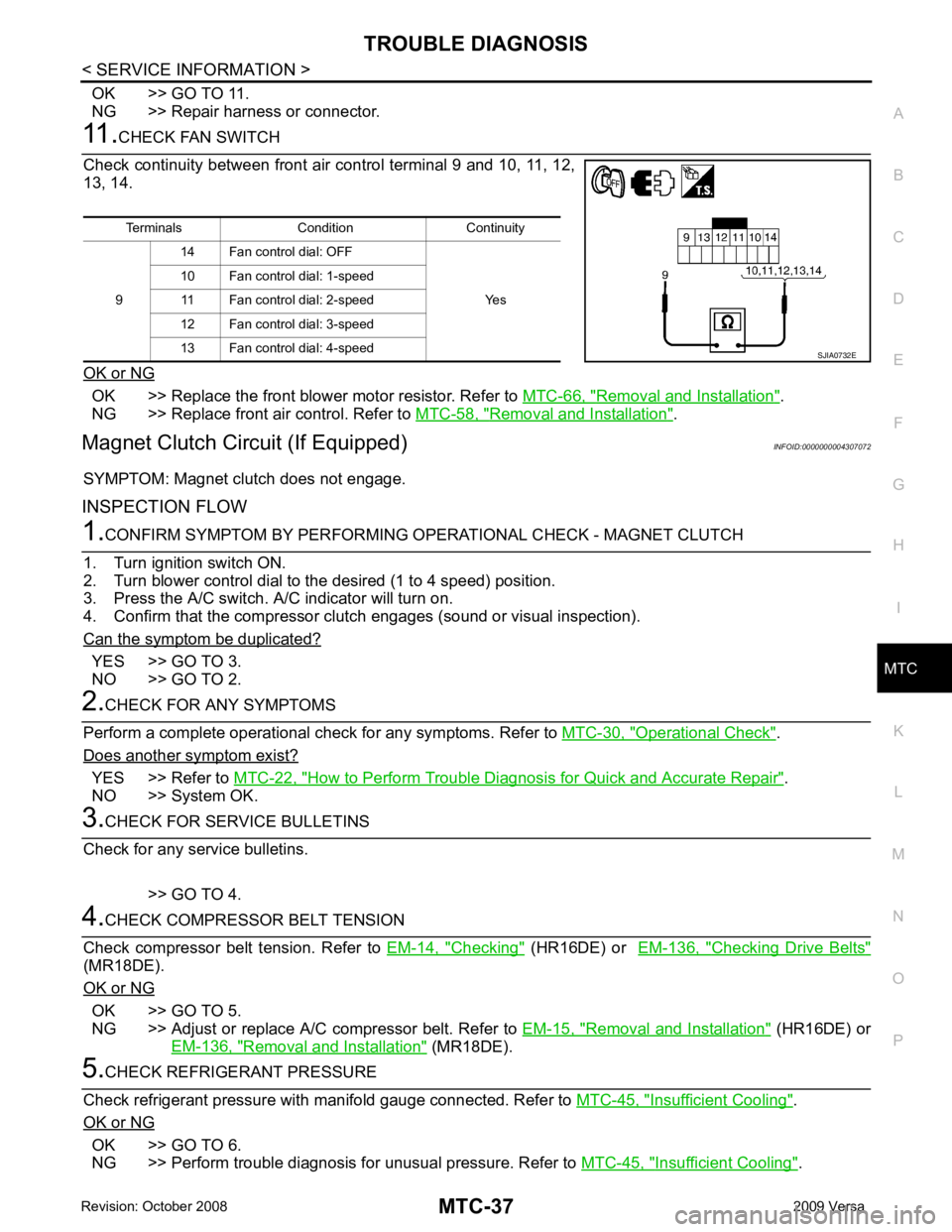
OK >> GO TO 11.
NG >> Repair harness or connector. OK >> Replace the front blower motor resistor. Refer to
MTC-66, " Removal and Installation " .
NG >> Replace front air control. Refer to MTC-58, " Removal and Installation " .
Magnet Clutch Circuit (If Equipped) INFOID:0000000004307072
SYMPTOM: Magnet clutch does not engage.
INSPECTION FLOW YES >> GO TO 3.
NO >> GO TO 2. Operational Check " .
Does another symptom exist? YES >> Refer to
MTC-22, " How to Perform Trouble Diagnosis for Quick and Accurate Repair " .
NO >> System OK. Checking " (HR16DE) or
EM-136, " Checking Drive Belts "
(MR18DE).
OK or NG OK >> GO TO 5.
NG >> Adjust or replace A/C compressor belt. Refer to EM-15, " Removal and Installation " (HR16DE) or
EM-136, " Removal and Installation " (MR18DE).
Insufficient Cooling " .
OK or NG OK >> GO TO 6.
NG >> Perform trouble diagnosis for unusual pressure. Refer to MTC-45, " Insufficient Cooling " .
Terminals Condition Continuity
9 14 Fan control dial: OFF
Yes
10 Fan control dial: 1-speed
11 Fan control dial: 2-speed
12 Fan control dial: 3-speed
13 Fan control dial: 4-speed