Page 3853 of 4331
MT
N
O P
Installation is in the reverse order of removal.
CAUTION:
When installing transaxle assembly, be careful not to bring transaxle input shaft into contact with
clutch cover.
• If transaxle is removed from the v ehicle, always replace CSC. Refer to CL-12, " Removal and Installation " .
• When installing the transaxle assembly to the engine, install the
bolts as shown.
A: M/T to engine
B: Engine to M/T
• After installation, bleed the air from the clutch hydraulic system. Refer to CL-8, " Air Bleeding Procedure " .
• After installation, check oil level, and check for leaks and loose mechanisms. Refer to MT-52, " Checking M/T
Oil " .
Disassembly and Assembly INFOID:0000000004305279
COMPONENTS
Case and Housing Components Bolt No. 1 2
Quantity 3 6
Bolt length “ ” mm (in) 60 (2.36) 50 (1.97)
Tightening torque
N·m (kg-m, ft-lb) 62.0 (6.3, 46)
Page 3859 of 4331
MT
N
O P
DISASSEMBLY
1. Remove drain plug and gasket from clutch hous ing using a suitable tool and drain gear oil.
2. Remove filler plug and gasket from transaxle case.
3. Remove select lever (1) retaining pin using a suitable tool, and then remove select lever.
4. Remove bracket (2) and position switch (3) from transaxle case. 1. Shim 2. Differential side bearing outer race
(transaxle case side) 3. Differential side bearing inner race
(transaxle case side)
4. Final gear 5. Differential case 6. Speedometer drive gear
7. Differential side bearing inner race (clutch housing side) 8. Differential side bearing outer race
(clutch housing side)
: Replace the parts as a set. PCIB1693E
Page 3861 of 4331

MT
N
O P
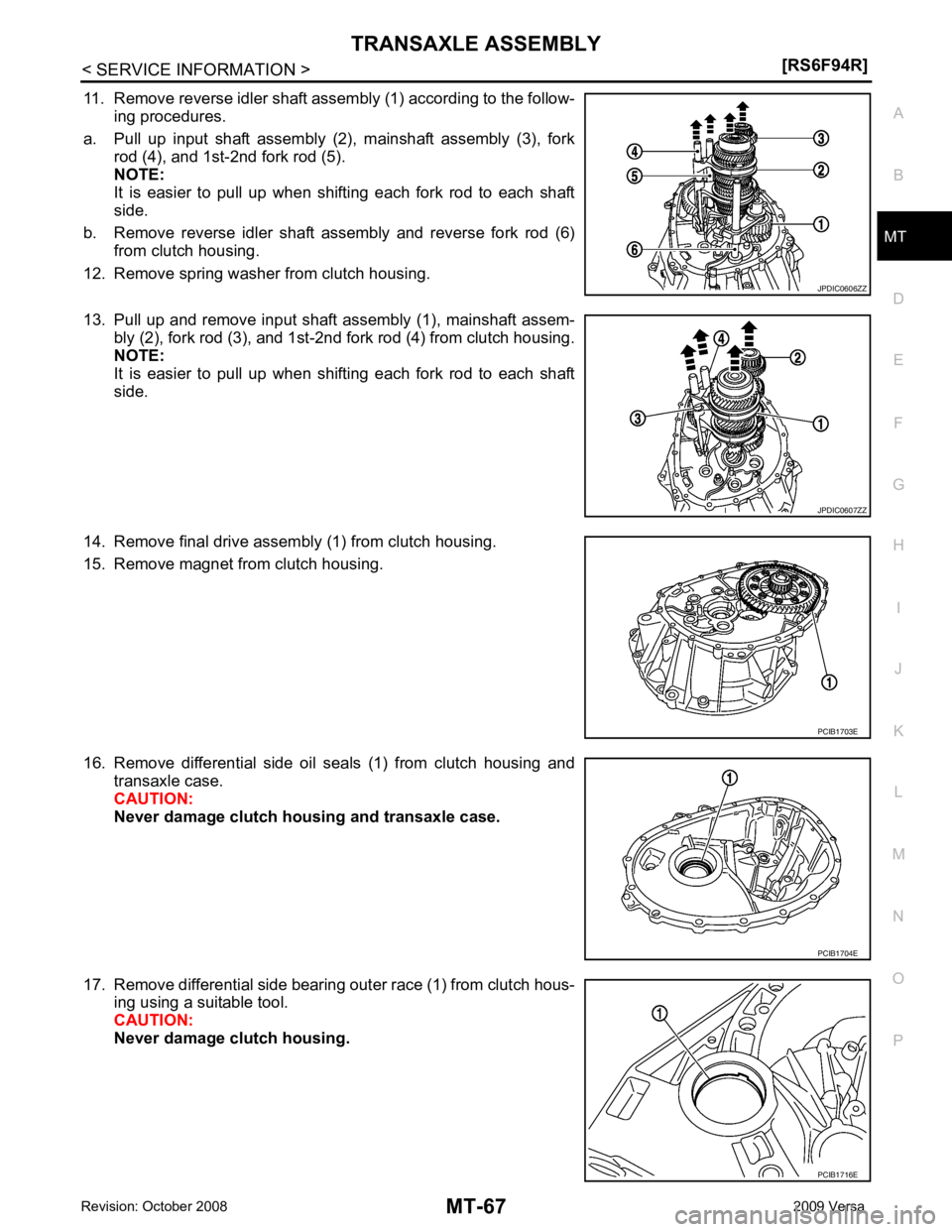
11. Remove reverse idler shaft assembly (1) according to the follow-
ing procedures.
a. Pull up input shaft assembly (2), mainshaft assembly (3), fork rod (4), and 1st-2nd fork rod (5).
NOTE:
It is easier to pull up when shifting each fork rod to each shaft
side.
b. Remove reverse idler shaft assembly and reverse fork rod (6) from clutch housing.
12. Remove spring washer from clutch housing.
13. Pull up and remove input shaft assembly (1), mainshaft assem- bly (2), fork rod (3), and 1st-2nd fork rod (4) from clutch housing.
NOTE:
It is easier to pull up when shifting each fork rod to each shaft
side.
14. Remove final drive assembly (1) from clutch housing.
15. Remove magnet from clutch housing.
16. Remove differential side oil seals (1) from clutch housing and transaxle case.
CAUTION:
Never damage clutch housing and transaxle case.
17. Remove differential side bearing outer race (1) from clutch hous- ing using a suitable tool.
CAUTION:
Never damage clutch housing. JPDIC0607ZZ
PCIB1703E
PCIB1716E
Page 3863 of 4331
MT
N
O P
25. Remove mainshaft rear bearing outer race from transaxle case
using a suitable tool.
26. Remove mainshaft rear bearing adjusting shim from transaxle case.
27. Remove snap ring (1) and oil channel (2) from transaxle case.
28. Remove input shaft oil seal (1) from clutch housing using a suit- able tool.
CAUTION:
Never damage clutch housing.
29. Remove mainshaft front bearing outer race (1) from clutch hous- ing using Tool (A) and a spacer (B).
30. Remove oil channel (2) from clutch housing.
31. Remove bushing (1) from clutch housing using a suitable tool. PCIB1708E
PCIB1714E
PCIB1717E
Page 3865 of 4331

MT
N
O P
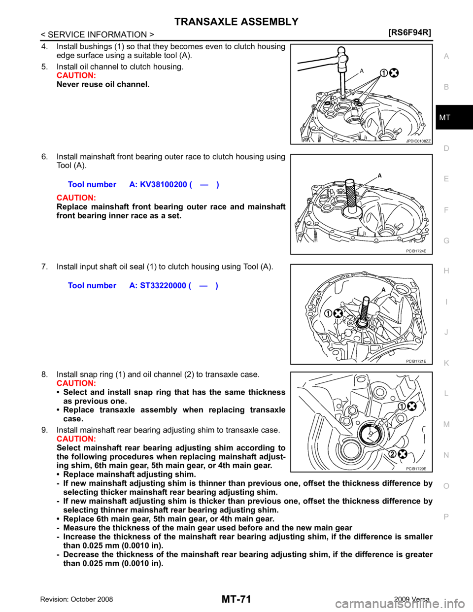
4. Install bushings (1) so that they becomes even to clutch housing
edge surface using a suitable tool (A).
5. Install oil channel to clutch housing. CAUTION:
Never reuse oil channel.
6. Install mainshaft front bearing outer race to clutch housing using Tool (A).
CAUTION:
Replace mainshaft front bearing outer race and mainshaft
front bearing inner race as a set.
7. Install input shaft oil seal (1) to clutch housing using Tool (A).
8. Install snap ring (1) and oil channel (2) to transaxle case. CAUTION:
• Select and install snap ring that has the same thickness
as previous one.
• Replace transaxle assembly wh en replacing transaxle
case.
9. Install mainshaft rear bearing adjusting shim to transaxle case. CAUTION:
Select mainshaft rear bearin g adjusting shim according to
the following procedures when replacing mainshaft adjust-
ing shim, 6th main gear, 5th main gear, or 4th main gear.
• Replace mainshaft adjusting shim.
- If new mainshaft adjusting shim is thinner th an previous one, offset the thickness difference by
selecting thicker mainshaft r ear bearing adjusting shim.
- If new mainshaft adjusting shim is thicker th an previous one, offset the thickness difference by
selecting thinner mainshaft r ear bearing adjusting shim.
• Replace 6th main gear, 5th main gear, or 4th main gear.
- Measure the thickness of the main gear used before and the new main gear
- Increase the thickness of the mainshaft rear bearin g adjusting shim, if the difference is smaller
than 0.025 mm (0.0010 in).
- Decrease the thickness of the mainshaft rear beari ng adjusting shim, if the difference is greater
than 0.025 mm (0.0010 in).
Page 3867 of 4331
MT
N
O P
17. Install differential side bearing outer race (transaxle case side)
to transaxle case using Tool (A).
CAUTION:
Replace differential side bearing outer race (transaxle case
side) and differential side bearing inner race (transaxle case
side) as a set.
18. Install differential side bearing outer race (clutch housing side) to clutch housing using Tool (A).
CAUTION:
Replace differential side bearing outer race (clutch housing
side) and differential side bearing inner race (clutch hous-
ing side) as a set.
19. Install differential side oil seals (1) to clutch housing and tran- saxle case using Tool.
• A: Transaxle case side
• B: Clutch housing side
20. Install magnet to clutch housing.
21. Install final drive assembly to clutch housing.
22. Set fork rod (1) to input shaft assembly (2), and then install them to clutch housing.Tool number A: ST33400001 (J-26082)
JPDIC0608ZZ
Page 3868 of 4331
![NISSAN LATIO 2009 Service Repair Manual MT-74< SERVICE INFORMATION >
[RS6F94R]
TRANSAXLE ASSEMBLY
23. Install mainshaft assembly (1) according to the following proce- dures.
a. Pull up input shaft assembly (2) and fork rod (3).
b. S NISSAN LATIO 2009 Service Repair Manual MT-74< SERVICE INFORMATION >
[RS6F94R]
TRANSAXLE ASSEMBLY
23. Install mainshaft assembly (1) according to the following proce- dures.
a. Pull up input shaft assembly (2) and fork rod (3).
b. S](/manual-img/5/57359/w960_57359-3867.png)
MT-74< SERVICE INFORMATION >
[RS6F94R]
TRANSAXLE ASSEMBLY
23. Install mainshaft assembly (1) according to the following proce- dures.
a. Pull up input shaft assembly (2) and fork rod (3).
b. Set 1st-2nd fork rod (4) to mainshaft assembly, and then install them to clutch housing.
24. Install reverse idler shaft assembly (1) according to the following procedures.
a. Install spring washer to clutch housing.
b. Pull up input shaft assembly (2), mainshaft assembly (3), fork rod (4), and 1st-2nd fork rod (5).
NOTE:
It is easier to pull up when shifting each fork rod to each shaft
side.
c. Set reverse fork rod (6) to reverse idler shaft assembly, and then install them to clutch housing.
25. Shift 1st-2nd fork rod (1), fork rod (2), and reverse fork rod (3) to the neutral position.
26. Install selector (4) to clutch housing. CAUTION:
Replace select lever and selector as a set.
27. Install selector spring (1) to return bushing (A).
28. Apply recommended sealant to transaxle case mounting sur- face.
• Use Genuine Silicone RTV or an equivalent. Refer to GI-42, " Recommended Chemical Product and Sealant " .
CAUTION:
• Never allow old liquid gasket , moisture, oil, or foreign
matter to remain on mounting surface.
• Check that mounting surface is not damaged.
• Apply liquid gasket bead continuously.
29. Install transaxle case to clutch housing while rotating shift lever A (1) in the direction as shown. JPDIC0609ZZ
JPDIC0606ZZ
SCIA7782E
JPDIC0445ZZ
JPDIC0110ZZ
Page 3869 of 4331
![NISSAN LATIO 2009 Service Repair Manual TRANSAXLE ASSEMBLY
MT-75
< SERVICE INFORMATION >
[RS6F94R] D
E
F
G H
I
J
K L
M A
B MT
N
O P
30. Install reverse idler shaft bolt ( ) according to the following pro-
cedures.
a. Install seal washer to NISSAN LATIO 2009 Service Repair Manual TRANSAXLE ASSEMBLY
MT-75
< SERVICE INFORMATION >
[RS6F94R] D
E
F
G H
I
J
K L
M A
B MT
N
O P
30. Install reverse idler shaft bolt ( ) according to the following pro-
cedures.
a. Install seal washer to](/manual-img/5/57359/w960_57359-3868.png)
TRANSAXLE ASSEMBLY
MT-75
< SERVICE INFORMATION >
[RS6F94R] D
E
F
G H
I
J
K L
M A
B MT
N
O P
30. Install reverse idler shaft bolt ( ) according to the following pro-
cedures.
a. Install seal washer to reverse idler shaft bolt, and install reverse idler shaft bolt to transaxle case.
CAUTION:
Never reuse seal washer.
b. Tighten reverse idler shaft bolt to the specified torque. Refer to MT-59, " Disassembly and Assembly " .
31. Tighten transaxle case bolts ( ) to the specified torque. Refer to MT-59, " Disassembly and Assembly " .
32. Install position switch (1) according to the following procedures.
a. Apply recommended sealant to position switch thread. •Use Genuine Silicone RTV or an equivalent. Refer to GI-42, " Recommended Chemical Product and Sealant " .
CAUTION:
Never allow old liquid gasket, mo isture, oil, or foreign mat-
ter to remain on thread.
b. Install position switch to transaxle case, and tighten it to the specified torque. Refer to MT-59, " Disassembly and Assembly " .
33. Install bracket (2) to transaxle case, and tighten bolt to the spec- ified torque. Refer to MT-59, " Disassembly and Assembly " .
34. Install select lever (3) according to following the procedures.
a. Install select lever to transaxle case. CAUTION:
Replace select lever and selector as a set.
b. Install retaining pin to select lever using a suitable tool. CAUTION:
Never reuse retaining pin.
35. Install drain plug according to the following procedures.
a. Install gasket to drain plug. CAUTION:
Never reuse gasket.
b. Install drain plug to clutch housing.
c. Tighten drain plug to the specified torque. Refer to MT-59, " Disassembly and Assembly " .
36. Install filler plug according to the following procedures.
a. Install gasket to filler plug, and then install them to transaxle case. CAUTION:
Never reuse gasket.
b. Tighten filler plug to the specified torque. Refer to MT-59, " Disassembly and Assembly " .
CAUTION:
Fill with gear oil before tighten fi ller plug to the specified torque. PCIB1695E
PCIB1694E
SCIA7784E