Page 3807 of 4331

MT
N
O P
CONTROL LINKAGE
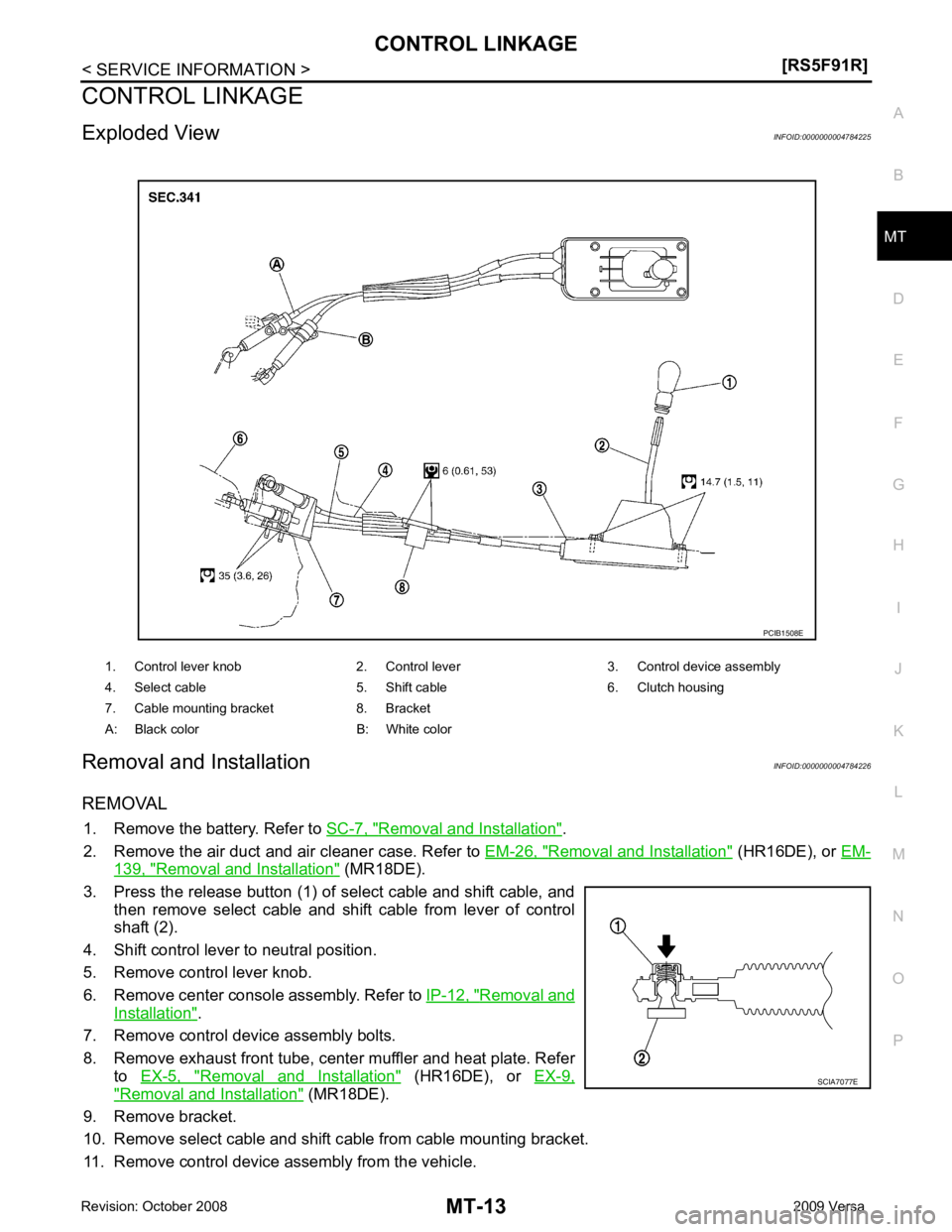
Exploded View INFOID:0000000004784225
Removal and Installation INFOID:0000000004784226
REMOVAL 1. Remove the battery. Refer to SC-7, " Removal and Installation " .
2. Remove the air duct and air cleaner case. Refer to EM-26, " Removal and Installation " (HR16DE), or
EM- 139, " Removal and Installation " (MR18DE).
3. Press the release button (1) of select cable and shift cable, and then remove select cable and shift cable from lever of control
shaft (2).
4. Shift control lever to neutral position.
5. Remove control lever knob.
6. Remove center console assembly. Refer to IP-12, " Removal and
Installation " .
7. Remove control device assembly bolts.
8. Remove exhaust front tube, cent er muffler and heat plate. Refer
to EX-5, " Removal and Installation " (HR16DE), or
EX-9," Removal and Installation " (MR18DE).
9. Remove bracket.
10. Remove select cable and shift c able from cable mounting bracket.
11. Remove control device assembly from the vehicle. 1. Control lever knob 2. Control lever 3. Control device assembly
4. Select cable 5. Shift cable 6. Clutch housing
7. Cable mounting bracket 8. Bracket
A: Black color B: White color
Page 3810 of 4331
Removal and Installa-
tion " .
REMOVAL
1. Drain gear oil. Refer to MT-10, " Draining " (RS5F91R),
MT-52, " Changing M/T Oil " (RS6F94R).
2. Drain clutch fluid and remove clutch tube from CSC. Refer to CL-12, " Removal and Installation " .
CAUTION:
Do not depress clutch pedal during removal procedure.
3. Remove the engine and transaxle as an assembly from the vehicle. Refer to EM-88, " Removal and Instal-
lation " (HR16DE),
EM-195, " Removal and Installation " (MR18DE).
4. Remove the transaxle to engine and engine to transaxle bolts.
5. Separate the transaxle assembly from the engine.
INSTALLATION 1. LH engine mount bracket (transaxle
side) 2. Transaxle assembly 3. Rear engine mount bracket
4. Washer 5. Rear torque rod ⇐: Front
: Refer to installation.
Page 3811 of 4331

MT
N
O P
Installation is in the reverse order of removal.
CAUTION:
• Make sure the transaxle assembly does not interfer e with the wire harnesses and clutch tube.
• When installing transaxle assembly, do not bring input shaft into contact with clutch cover.
• If transaxle is removed from the vehicle, always replace CSC. Refer to CL-12, " Removal and Installa-
tion " .
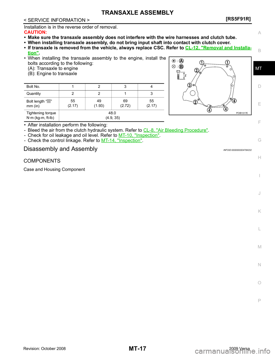
• When installing the transaxle assembly to the engine, install the bolts according to the following:
(A): Transaxle to engine
(B): Engine to transaxle
• After installation perform the following:
- Bleed the air from the clutch hydraulic system. Refer to CL-8, " Air Bleeding Procedure " .
- Check for oil leakage and oil level. Refer to MT-10, " Inspection " .
- Check the control linkage. Refer to MT-14, " Inspection " .
Disassembly and Assembly INFOID:0000000004784232
COMPONENTS
Case and Housing Component Bolt No. 1 2 3 4
Quantity 2 2 1 3
Bolt length “ ”
mm (in) 55
(2.17) 49
(1.93) 69
(2.72) 55
(2.17)
Tightening torque
N·m (kg-m, ft-lb) 48.0
(4.9, 35)
Page 3819 of 4331
MT
N
O P
18. Remove 1st-2nd fork rod assembly (1) and mainshaft assembly
(2) from clutch housing at the same time.
19. Remove retaining pin from 1st-2nd shift fork using a suitable tool.
20. Remove 1st-2nd shift fork from 1st-2nd shift fork rod.
21. Remove retaining pin from reverse gear assembly using a suit- able tool.
22. Remove reverse gear assembly from clutch housing.
23. Remove final drive assembly (1) from clutch housing.
24. Remove pinion shaft and pinion gear from clutch housing.
25. Remove magnet and dowel pins (2) from clutch housing.
26. Remove input shaft front bearing from clutch housing using a suitable tool.
27. Cut oil channel tube at the root.
28. Remove mainshaft front bearing and oil channel from clutch housing using Tool (A). MCIB0033E
Page 3823 of 4331

MT
N
O P
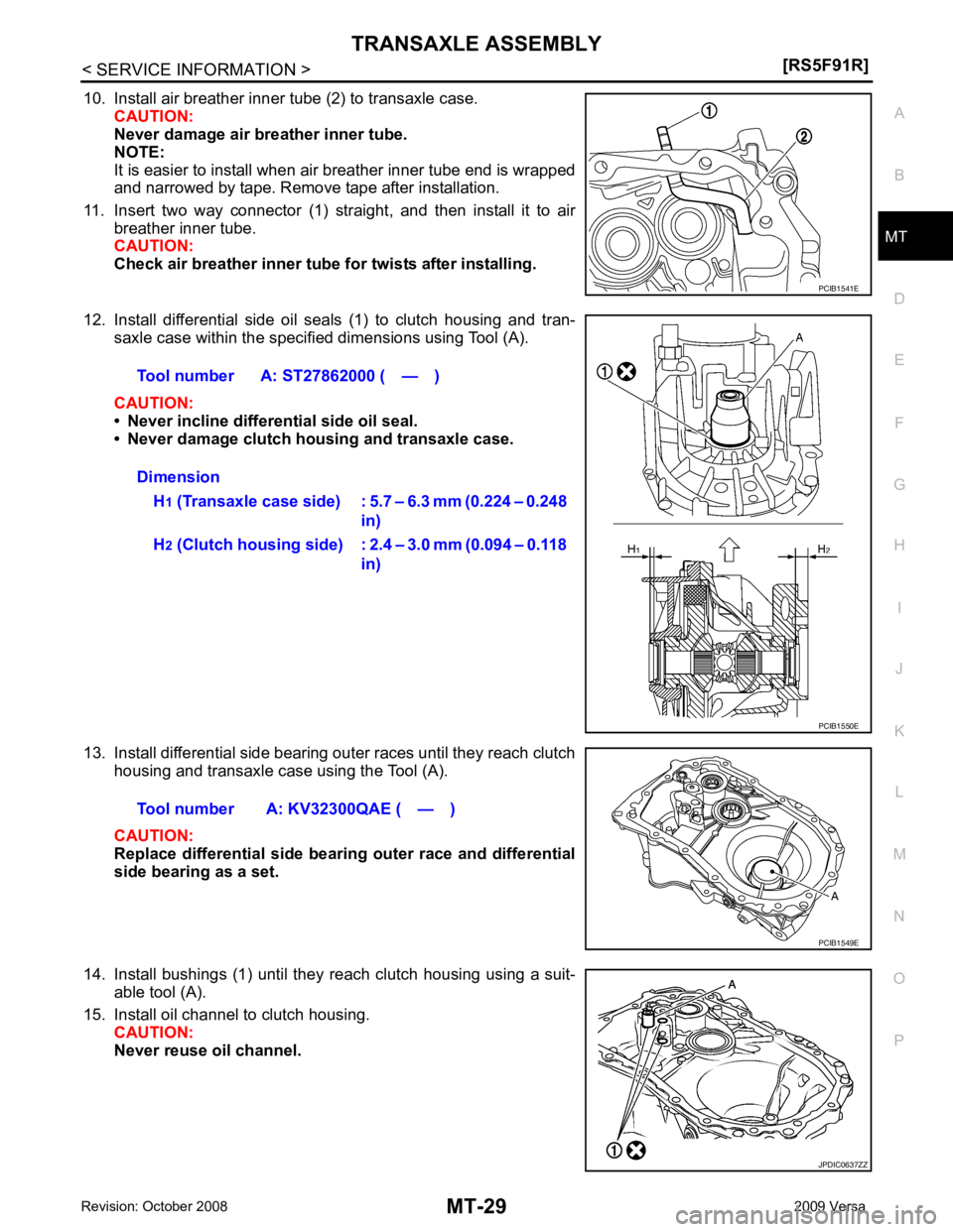
10. Install air breather inner tube (2) to transaxle case.
CAUTION:
Never damage air breather inner tube.
NOTE:
It is easier to install when air breather inner tube end is wrapped
and narrowed by tape. Remove tape after installation.
11. Insert two way connector (1) straight, and then install it to air breather inner tube.
CAUTION:
Check air breather inner tube fo r twists after installing.
12. Install differential side oil seals (1) to clutch housing and tran- saxle case within the specified dimensions using Tool (A).
CAUTION:
• Never incline differential side oil seal.
• Never damage clutch housing and transaxle case.
13. Install differential side bearing outer races until they reach clutch housing and transaxle case using the Tool (A).
CAUTION:
Replace differential side bearing outer race and differential
side bearing as a set.
14. Install bushings (1) until they reach clutch housing using a suit- able tool (A).
15. Install oil channel to clutch housing. CAUTION:
Never reuse oil channel. JPDIC0637ZZ
Page 3824 of 4331
![NISSAN LATIO 2009 Service Repair Manual MT-30< SERVICE INFORMATION >
[RS5F91R]
TRANSAXLE ASSEMBLY
16. Install mainshaft front bearing so that it becomes even to clutch housing surface using Tool (A) .
17. Install input shaft front bearing s NISSAN LATIO 2009 Service Repair Manual MT-30< SERVICE INFORMATION >
[RS5F91R]
TRANSAXLE ASSEMBLY
16. Install mainshaft front bearing so that it becomes even to clutch housing surface using Tool (A) .
17. Install input shaft front bearing s](/manual-img/5/57359/w960_57359-3823.png)
MT-30< SERVICE INFORMATION >
[RS5F91R]
TRANSAXLE ASSEMBLY
16. Install mainshaft front bearing so that it becomes even to clutch housing surface using Tool (A) .
17. Install input shaft front bearing so that it becomes even to clutch
housing surface using Tool (A).
18. Install pinion gear and pinion shaft to clutch housing.
19. Install final drive assembly (1) to clutch housing.
20. Install dowel pins (2) and magnet to clutch housing.
21. Install reverse gear assembly to clutch housing, and then install retaining pin to clutch housing using a suitable tool.
CAUTION:
Never reuse retaining pin.
22. Install 1st-2nd shift fork to 1st-2nd fork rod, and then install retaining pin to 1st-2nd shift fork.
CAUTION:
• Never reuse retaining pin.
• Replace 1st-2nd fork rod and 1st-2nd shift fork as a set.
23. Set 1st-2nd fork rod assembly (1) onto mainshaft assembly (2), and then install them to clutch housing.Tool number A: ST33400001 (J-26082) PCIB1544E
Tool number A: KV40100900 ( — )
PCIB1545E
PCIB1533E
MCIB0033E
PCIB1532E
Page 3825 of 4331
![NISSAN LATIO 2009 Service Repair Manual TRANSAXLE ASSEMBLY
MT-31
< SERVICE INFORMATION >
[RS5F91R] D
E
F
G H
I
J
K L
M A
B MT
N
O P
24. Install lock pins ( ) to clutch housing.
25. Install 3rd-4th shift fork to 3rd-4th fork rod, and NISSAN LATIO 2009 Service Repair Manual TRANSAXLE ASSEMBLY
MT-31
< SERVICE INFORMATION >
[RS5F91R] D
E
F
G H
I
J
K L
M A
B MT
N
O P
24. Install lock pins ( ) to clutch housing.
25. Install 3rd-4th shift fork to 3rd-4th fork rod, and](/manual-img/5/57359/w960_57359-3824.png)
TRANSAXLE ASSEMBLY
MT-31
< SERVICE INFORMATION >
[RS5F91R] D
E
F
G H
I
J
K L
M A
B MT
N
O P
24. Install lock pins ( ) to clutch housing.
25. Install 3rd-4th shift fork to 3rd-4th fork rod, and then install retaining pin to 3rd-4th shift fork.
CAUTION:
• Never reuse retaining pin.
• Replace 3rd-4th fork rod and 3rd-4th shift fork as a set.
26. Install 3rd-4th fork rod assembly (1), 3rd-4th coupling sleeve (2), and input shaft assembly (3) to clutch housing according to the
following procedures.
a. Pull 1st-2nd fork rod (4) up, and then maintain the neutral posi- tion.
b. Set 3rd-4th fork rod assembly onto 3rd-4th coupling sleeve, and then install them together with input shaft assembly to clutch
housing.
CAUTION:
• Set lock pin (3rd-4th fork rod side) onto 1st-2nd fork rod groove and then install 3rd-4th fork rod assembly.
• Be careful with the orientat ion of 3rd-4th coupling sleeve.
- A: 4th main gear side
- B: 3rd main gear side
• Install 3rd input gear of in put shaft assembly so that it is
set under reverse main gear of 3rd-4th coupling sleeve.
• Replace 3rd-4th coupling sl eeve and 3rd-4th synchronizer
hub as a set.
c. Install springs and insert keys to 3rd-4th synchronizer hub.
d. Apply gear oil to 4th baulk ring.
e. Install 4th baulk ring.
27. Install 5th-reverse fork rod (1) to clutch housing according to the following procedures.
CAUTION:
Replace 5th-reverse fork rod and 5th-reverse shift fork as a
set.
a. Pull gear of reverse gear assembly (2) up.
b. Temporarily install 5th-reverse fork rod to clutch housing. JPDIC0534ZZ
PCIB1628E
PCIB1551E
MCIB0061E
PCIB1629E
Page 3826 of 4331
Rec-
ommended Chemical Product and Sealant " .
CAUTION:
• Never allow old liquid gasket, moisture, oil, or foreign matter to remain on mounting surface.
• Check that mounting surface is not damaged.
• Apply a continuous bead of liqu id gasket to the mounting surface.
32. Install transaxle case to clutch housing. If it is difficult to install, slightly rotate control shaft shift lever counterclockwise, and then
install.
• 1: Selector
• 2: Shift fork
CAUTION:
• Never disrupt liquid gasket bead with transaxle case or
other objects during installation.
• Be careful to align the lever of 5th-reverse fork rod with
reverse gear assembly groove. PCIB1529E
PCIB1524E
PCIB1553E