2009 NISSAN LATIO fuse
[x] Cancel search: fusePage 408 of 4331
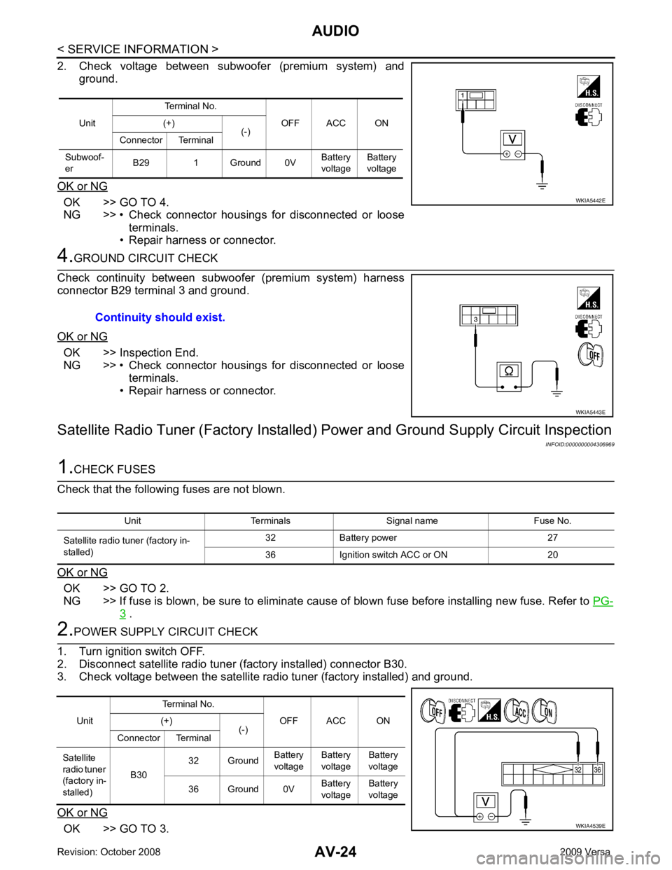
OK >> GO TO 4.
NG >> • Check connector housings for disconnected or loose
terminals.
• Repair harness or connector. OK >> Inspection End.
NG >> • Check connector housings for disconnected or loose
terminals.
• Repair harness or connector.
Satellite Radio Tuner (Factory Installed) Power and Ground Supply Circuit Inspection
INFOID:0000000004306969OK >> GO TO 2.
NG >> If fuse is blown, be sure to eliminate cause of blown fuse before installing new fuse. Refer to PG-3 .
OK >> GO TO 3.Unit
Terminal No.
OFF ACC ON
(+)
(-)
Connector Terminal
Subwoof-
er B29 1 Ground 0V Battery
voltage Battery
voltage Unit
Terminal No.
OFF ACC ON
(+)
(-)
Connector Terminal
Satellite
radio tuner
(factory in-
stalled) B30
32 Ground
Battery
voltage Battery
voltage Battery
voltage
36 Ground 0V Battery
voltage Battery
voltage
Page 419 of 4331
AV
N
O P
Sound Is Not Heard from Su
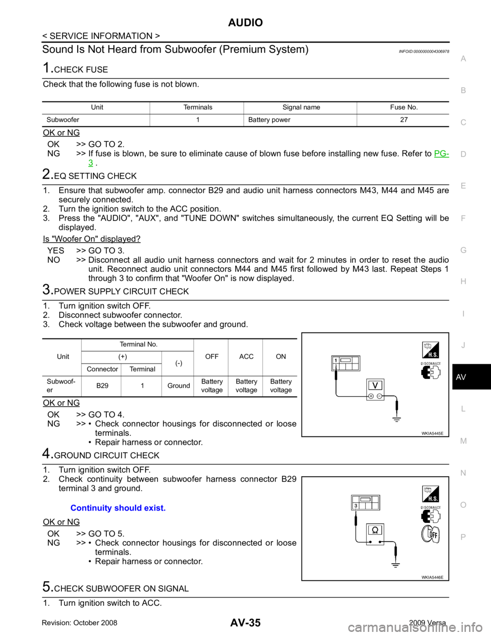
bwoofer (Premium System) INFOID:0000000004306978OK >> GO TO 2.
NG >> If fuse is blown, be sure to eliminate cause of blown fuse before installing new fuse. Refer to PG-3 .
YES >> GO TO 3.
NO >> Disconnect all audio unit harness connectors and wait for 2 minutes in order to reset the audio
unit. Reconnect audio unit connectors M44 and M45 first followed by M43 last. Repeat Steps 1
through 3 to confirm that "Woofer On" is now displayed. OK >> GO TO 4.
NG >> • Check connector housings for disconnected or loose terminals.
• Repair harness or connector. OK >> GO TO 5.
NG >> • Check connector housings for disconnected or loose terminals.
• Repair harness or connector. Unit
Terminal No.
OFF ACC ON
(+)
(-)
Connector Terminal
Subwoof-
er B29 1 Ground Battery
voltage Battery
voltage Battery
voltage
Page 435 of 4331
AV
N
O P
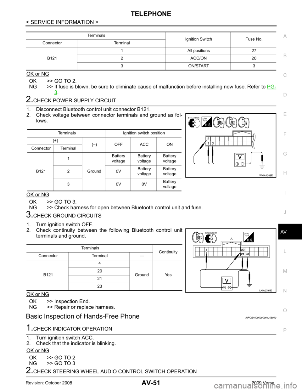
OK or NG OK >> GO TO 2.
NG >> If fuse is blown, be sure to eliminate caus e of malfunction before installing new fuse. Refer to PG-3 .
OK >> GO TO 3.
NG >> Check harness for open between Bluetooth control unit and fuse. OK >> Inspection End.
NG >> Repair or replace harness.
Basic Inspection of Hands-Free Phone INFOID:0000000004306990OK >> GO TO 2
NG >> GO TO 3 Terminals Ignition switch position
(+) (–) OFF ACC ON
Connector Terminal
B121 1
Ground Battery
voltage Battery
voltage Battery
voltage
2 0V Battery
voltage Battery
voltage
3 0V 0V Battery
voltage
Page 457 of 4331
BCS
N
O P
1: With Intelligent Key
2: Without Intelligent Key
3: Hatchback without Intelligent Key
4: Sedan without Intelligent Key
5: Hatchback
6: Sedan
7: With power door locks
8: With power windows
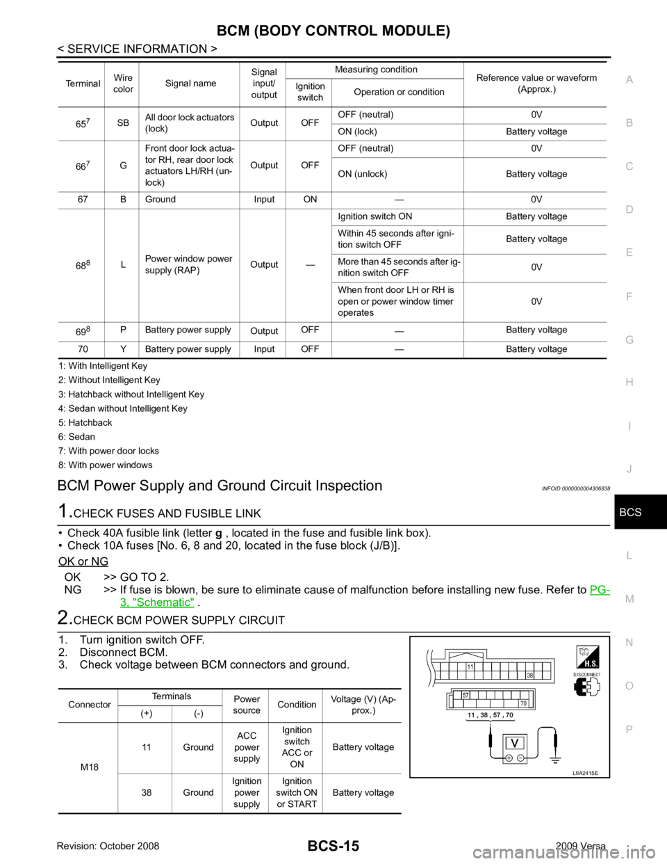
BCM Power Supply and Gr ound Circuit Inspection INFOID:0000000004306838OK >> GO TO 2.
NG >> If fuse is blown, be sure to eliminate caus e of malfunction before installing new fuse. Refer to PG-3, " Schematic " .
Connector
Terminals
Power
source Condition Voltage (V) (Ap-
prox.)
(+) (-)
M18 11 Ground
ACC
power
supply Ignition
switch
ACC or
ON Battery voltage
38 Ground Ignition
power
supply Ignition
switch ON or START Battery voltage
Page 484 of 4331

BL
N
O P
System Description
INFOID:0000000004304987
Power is supplied at all times
• through 40A fusible link (letter g , located in the fuse and fusible link box)
• to BCM terminal 70
• through 10A fuse [No. 8, located in the fuse block (J/B)]
• to BCM terminal 57
• through 10A fuse [No. 14, located in the fuse block (J/B)]
• to key switch terminal 2 (without Intelligent Key system)
• through 10A fuse [No. 31, located in the fuse block (J/B)]
• to key switch and ignition knob switch terminals 2 and 4 (with Intelligent Key system).
When key switch is ON (key is inserted in ignition key cylinder), power is supplied
• through key switch terminal 1 (without Intelligent Key system) or key switch and ignition knob terminal 1 (with Intelligent Key system)
• to BCM terminal 37.
Ground is supplied
• to BCM terminal 67
• through body grounds M57 and M61.
LOCK OPERATION When the door is locked with main power window and door lock/unlock switch, ground is supplied
• to BCM terminal 45
• through main power window and door lock and unlock switch terminals 17 and 18
• through body grounds M57 and M61.
When the door is locked with power window and door lock/unlock switch RH, ground is supplied
• to BCM terminal 45
• through power window and door lock and unlock switch RH terminals 1 and 3
• through body grounds M57 and M61.
When the door is locked with front door ke y cylinder switch LH, ground is supplied
• to BCM terminal 8
• through front door key cylinder switch LH terminals 1 and 2
• through body grounds M57 and M61.
UNLOCK OPERATION When the door is unlocked with main power window and door lock/unlock switch, ground is supplied
• to BCM terminal 46
• through main power window and door lock/unlock switch terminals 6 and 17
• through body grounds M57 and M61.
When the door is unlocked with power window and door lock/unlock switch RH, ground is supplied
• to BCM terminal 46
• through power window and door lock and unlock switch RH terminals 2 and 3
• through body grounds M57 and M61.
When the door is unlocked with front door ke y cylinder switch LH, ground is supplied
• to BCM terminal 7
• through front door key cylinder switch LH terminals 2 and 3
• through body grounds M57 and M61.
When the front door switch LH is ON (door is OPEN), ground is supplied
• to BCM terminal 47
• through front door switch LH terminal 2
• through front door switch LH case ground.
When the front door switch RH is ON (door is OPEN), ground is supplied
• to BCM terminal 12
• through front door switch RH terminal 2
• through front door switch RH case ground. 10. Key switch and key lock solenoid M27
(without Intelligent key) 11. Main power window and door lock/un-
lock switch D7, D8
Power window and door lock/unlock
switch RH D105 12. Fuse block (with Intelligent Key)
(view with instrument panel LH re-
moved)
13. Passenger select unlock relay M2 (with Intelligent Key) 14. Back door lock assembly (back door
switch) D405 (hatchback view with back
door open) 15. Combination meter M24
Page 504 of 4331
BL
N
O P
*: With Remote Keyless Entry system
**: With Intelligent Key system
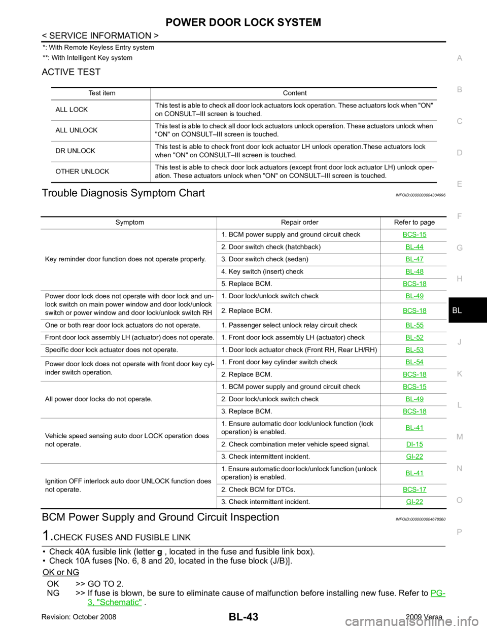
ACTIVE TEST
Trouble Diagnosis Symptom Chart INFOID:0000000004304996
BCM Power Supply and Gr ound Circuit Inspection INFOID:0000000004678560OK >> GO TO 2.
NG >> If fuse is blown, be sure to eliminate caus e of malfunction before installing new fuse. Refer to PG-3, " Schematic " .
Test item Content
ALL LOCK This test is able to check all door lock actuators lock operation. These actuators lock when "ON"
on CONSULT–III screen is touched.
ALL UNLOCK This test is able to check all door lock actuators unlock operation. These actuators unlock when
"ON" on CONSULT–III screen is touched.
DR UNLOCK This test is able to check front door lock actuator LH unlock operation.These actuators lock
when "ON" on CONSULT– III screen is touched.
OTHER UNLOCK This test is able to check door lock actuators (except front door lock actuator LH) unlock oper-
ation. These actuators unlock when "ON" on CONSULT–III screen is touched. Symptom Repair order Refer to page
Key reminder door function does not operate properly. 1. BCM power supply and ground circuit check
BCS-15 2. Door switch check (hatchback)
BL-44 3. Door switch check (sedan)
BL-47 4. Key switch (insert) check
BL-48 5. Replace BCM.
BCS-18Power door lock does not operate with door lock and un-
lock switch on main power window and door lock/unlock
switch or power window and door lock/unlock switch RH 1. Door lock/unlock switch check
BL-49 2. Replace BCM.
BCS-18One or both rear door lock actuators do not operate. 1. Passenger select unlock relay circuit check
BL-55Front door lock assembly LH (actuator) does not operate. 1. Front door lock assembly LH (actuator) check
BL-52Specific door lock actuator does not operate. 1. Door lock actuator check (Front RH, Rear LH/RH)
BL-53Power door lock does not operate with front door key cyl-
inder switch operation. 1. Front door key cylinder switch check
BL-54 2. Replace BCM.
BCS-18All power door locks do not operate.
1. BCM power supply and ground circuit check
BCS-15 2. Door lock/unlock switch check
BL-49 3. Replace BCM.
BCS-18Vehicle speed sensing auto door LOCK operation does
not operate. 1. Ensure automatic door lock/unlock function (lock
operation) is enabled. BL-41 2. Check combination meter vehicle speed signal.
DI-15 3. Check intermittent incident.
GI-22Ignition OFF interlock auto door UNLOCK function does
not operate. 1. Ensure automatic door lock/unlock function (unlock
operation) is enabled. BL-41 2. Check BCM for DTCs.
BCS-17 3. Check intermittent incident.
GI-22
Page 510 of 4331
BL
N
O P
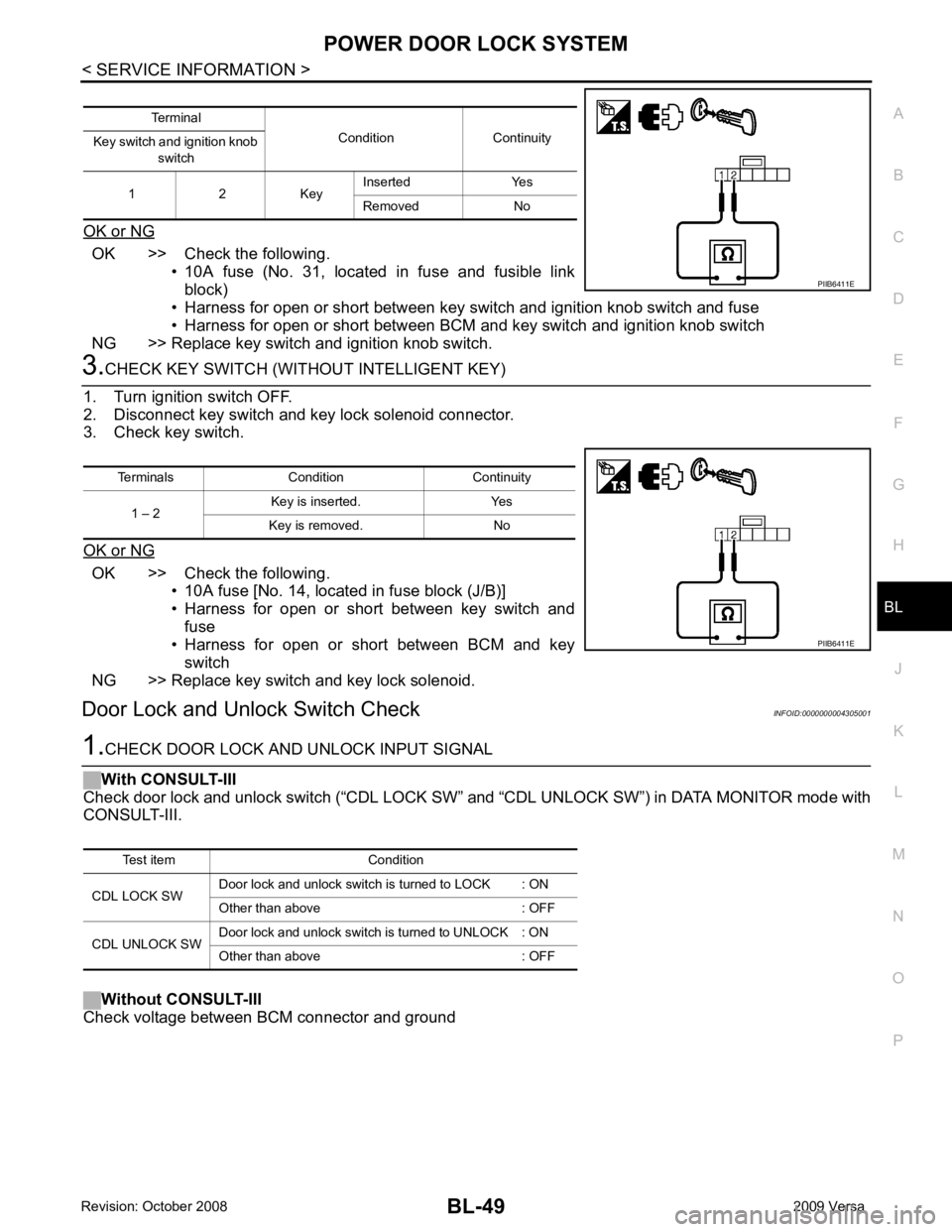
OK or NG OK >> Check the following.
• 10A fuse (No. 31, located in fuse and fusible link
block)
• Harness for open or short between key switch and ignition knob switch and fuse
• Harness for open or short between BCM and key switch and ignition knob switch
NG >> Replace key switch and ignition knob switch. OK >> Check the following.
• 10A fuse [No. 14, located in fuse block (J/B)]
• Harness for open or short between key switch and fuse
• Harness for open or short between BCM and key
switch
NG >> Replace key switch and key lock solenoid.
Door Lock and Unlock Switch Check INFOID:0000000004305001
Page 520 of 4331
![NISSAN LATIO 2009 Service Repair Manual BL
N
O P
• through 10A fuse [No. 14, located in the fuse block (J/B)]
• through key switch terminals 2 and 1
• to BCM terminal 37.
When the ignition switch is ACC or ON, power is supplied
• th NISSAN LATIO 2009 Service Repair Manual BL
N
O P
• through 10A fuse [No. 14, located in the fuse block (J/B)]
• through key switch terminals 2 and 1
• to BCM terminal 37.
When the ignition switch is ACC or ON, power is supplied
• th](/manual-img/5/57359/w960_57359-519.png)
BL
N
O P
• through 10A fuse [No. 14, located in the fuse block (J/B)]
• through key switch terminals 2 and 1
• to BCM terminal 37.
When the ignition switch is ACC or ON, power is supplied
• through 10A fuse [No. 20, located in the fuse block (J/B)]
• to BCM terminal 11.
Ground is supplied
• to BCM terminal 67
• through body grounds M57 and M61.
When the front door switch LH is ON (door is OPEN), ground is supplied
• to BCM terminal 47
• through front door switch LH terminal 2
• through front door switch LH case ground.
When the front door switch RH is ON (door is OPEN), ground is supplied
• to BCM terminal 12
• through front door switch RH terminal 2
• through front door switch RH case ground.
When the rear door switch LH is ON (door is OPEN), ground is supplied
• to BCM terminal 48
• through rear door switch LH terminal 1
• through rear door switch LH case ground.
When the rear door switch RH is ON (door is OPEN), ground is supplied
• to BCM meter terminal 13
• through rear door switch RH terminal 1
• through rear door switch RH case ground.
When the back door lock assembly (back door switch) (hat chback) is ON (back door is OPEN), ground is sup-
plied
• to BCM terminal 43
• through back door lock assembly (back door switch) terminals 3 and 4
• through body grounds B117, B132 and D402.
Keyfob signal is inputted to BCM from remote keyless entry receiver.
The remote keyless entry system controls operation of the
• power door lock
• hazard reminder
• auto door lock
• panic alarm
• room lamp
OPERATED PROCEDURE
Power Door Lock Operation BCM receives a LOCK signal from keyfob. BCM lock s all doors with input of LOCK signal from keyfob.
BCM receives a UNLOCK signal from keyfob. BCM unlocks all doors with input of UNLOCK signal from key-
fob.
Hazard and Horn Reminder When the doors are locked or unlocked by keyfob, power is supplied to sound horn and flash hazard warning
lamps as follows
• LOCK operation: 3 or 4 mode (lamps flash twice)
• UNLOCK operation: 2 or 4 mode (lamps flash once)
• Horn sounds once with LOCK function when this feature is set ON.
The hazard reminder has modes 1, 2, 3 or 4. The hor n reminder can be turned ON/OFF with any LOCK mode.
Operating function of hazard reminder
Hazard and horn reminders do not operate if any door switch is ON (any door is OPEN).
How to change hazard and horn reminder modes Mode 1 Mode 2 Mode 3 Mode 4
Keyfob operation Lock Unlock Lock Unlock Lock Unlock Lock Unlock
Hazard warning lamp
flash — — — Twice Once — Once Twice
Horn sound (ON/OFF) ON: once — O N: once — ON: once — ON: once —