Page 535 of 4331
YES >> Key fob is OK.
NO >> Check remote keyless entry receiver. Refer to BL-80," Remote Keyless Entry Receiver Check " .
ACC Switch Check INFOID:0000000004305018OK >> ACC switch is OK.
NG >> Check the following. • 10A fuse [No. 20, located in fuse block (J/B)]
• Harness for open or short between BCM and fuse.
Door Switch Check (Hatchback) INFOID:0000000004305019CONSULT-III Function (BCM) " .
• When doors are open: Terminals
Ignition switch
condition Voltage (V)
(Approx.)
(+)
(–)
BCM connector Terminal
M18 11 Ground ACC or ON Battery voltage
OFF 0
Page 539 of 4331
BL-78< SERVICE INFORMATION >
REMOTE KEYLESS ENTRY SYSTEM
Key Switch (I nsert) Check INFOID:00000000043050211.
CHECK KEY SWITCH INPUT SIGNAL
With CONSULT-III
Check key switch "KEY ON SW" in DATA MONITOR mode with CONSULT–III. Refer to BL-41, " CONSULT-III
Function (BCM) " .
• When key is inserted into ignition key cylinder:
• When key is removed from ignition key cylinder:
Without CONSULT-III
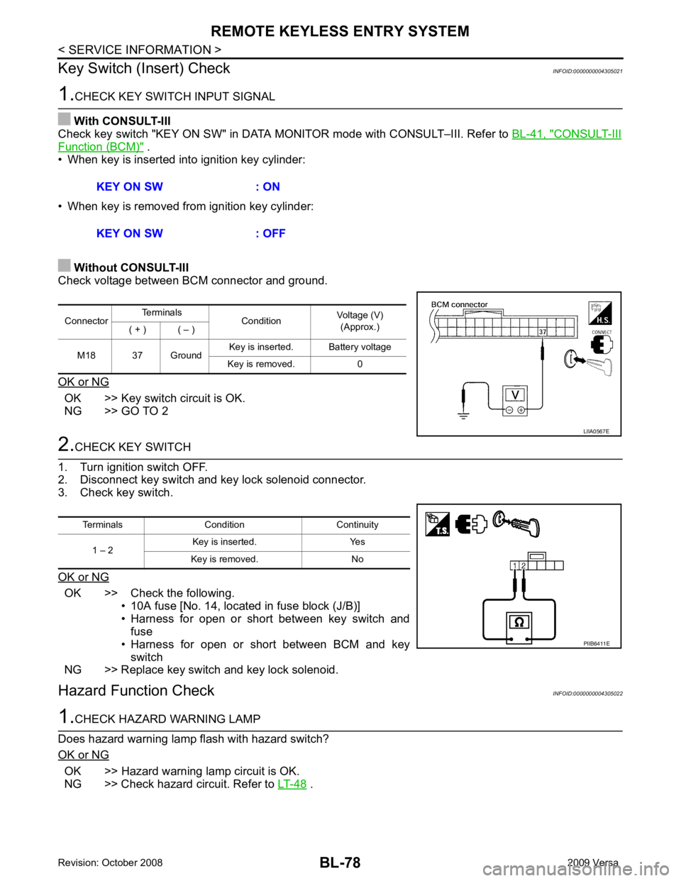
Check voltage between BCM connector and ground.
OK or NG OK >> Key switch circuit is OK.
NG >> GO TO 2 2.
CHECK KEY SWITCH
1. Turn ignition switch OFF.
2. Disconnect key switch and key lock solenoid connector.
3. Check key switch.
OK or NG OK >> Check the following.
• 10A fuse [No. 14, located in fuse block (J/B)]
• Harness for open or short between key switch and fuse
• Harness for open or short between BCM and key switch
NG >> Replace key switch and key lock solenoid.
Hazard Function Check INFOID:00000000043050221.
CHECK HAZARD WARNING LAMP
Does hazard warning lamp flash with hazard switch?
OK or NG OK >> Hazard warning lamp circuit is OK.
NG >> Check hazard circuit. Refer to LT-48 .
KEY ON SW : ON
KEY ON SW : OFF Connector
Terminals
ConditionVoltage (V)
(Approx.)
( + ) ( – )
M18 37 Ground Key is inserted. Battery voltage
Key is removed. 0 LIIA0567E
Terminals Condition Continuity
1 – 2 Key is inserted. Yes
Key is removed. No PIIB6411E
Page 590 of 4331
INTELLIGENT KEY SYSTEM
BL-129
< SERVICE INFORMATION >
C
D E
F
G H
J
K L
M A
B BL
N
O P
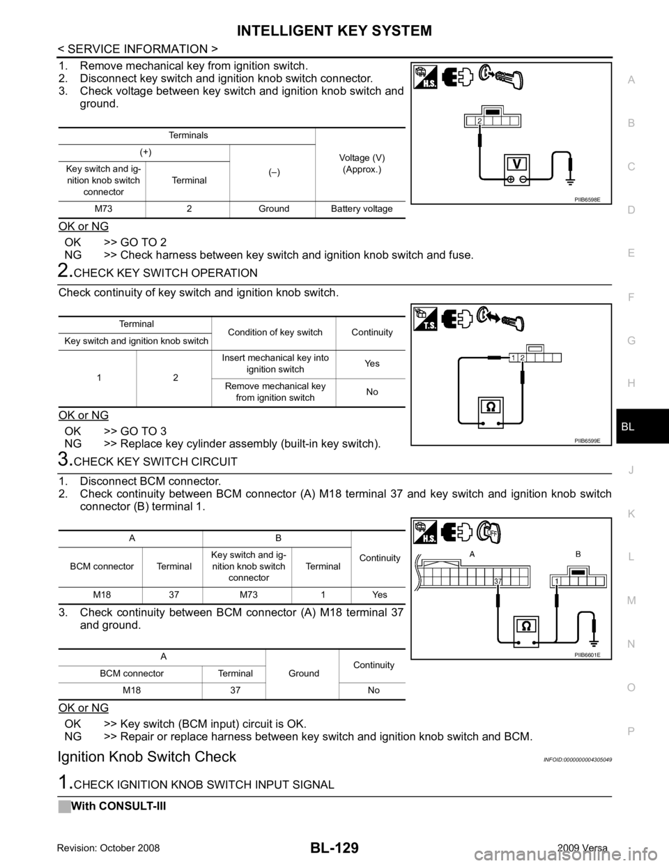
1. Remove mechanical key from ignition switch.
2. Disconnect key switch and i gnition knob switch connector.
3. Check voltage between key switch and ignition knob switch and
ground.
OK or NG OK >> GO TO 2
NG >> Check harness between key switch and ignition knob switch and fuse. 2.
CHECK KEY SWITCH OPERATION
Check continuity of key switch and ignition knob switch.
OK or NG OK >> GO TO 3
NG >> Replace key cylinder assembly (built-in key switch). 3.
CHECK KEY SWITCH CIRCUIT
1. Disconnect BCM connector.
2. Check continuity between BCM connector (A) M18 terminal 37 and key switch and ignition knob switch
connector (B) terminal 1.
3. Check continuity between BCM connector (A) M18 terminal 37 and ground.
OK or NG OK >> Key switch (BCM input) circuit is OK.
NG >> Repair or replace harness between key switch and ignition knob switch and BCM.
Ignition Knob Switch Check INFOID:00000000043050491.
CHECK IGNITION KNOB SWITCH INPUT SIGNAL
With CONSULT-III Terminals
Voltage (V)(Approx.)
(+)
(–)
Key switch and ig-
nition knob switch
connector Terminal
M73 2 Ground Battery voltage PIIB6598E
Terminal
Condition of key switch Continuity
Key switch and ignition knob switch
1 2 Insert mechanical key into
ignition switch Yes
Remove mechanical key from ignition switch No PIIB6599E
A B
Continuity
BCM connector Terminal Key switch and ig-
nition knob switch connector Terminal
M18 37 M73 1 Yes
A GroundContinuity
BCM connector Terminal
M18 37 No PIIB6601E
Page 611 of 4331
OK >> GO TO 3
NG >> Repair or replace harness. OK >> Key switch and ignition knob switch is OK.
NG >> Replace key switch and ignition knob switch.
Ignition Switch Position Check INFOID:0000000004305062OK >> Ignition power supply is OK.
NG >> Check the following.
• Intelligent Key unit power supply circuit.
• 10A fuse [No. 2, located in the fuse block (J/B)]
Stop Lamp Switch Check (With CVT or A/T) INFOID:0000000004305063
Page 612 of 4331
BL
N
O P
2. Disconnect Intelligent Key unit connector.
3. Check voltage between Intelligent Key unit harness connector M52 terminal 26 and ground.
OK or NG OK >> Stop lamp switch is OK.
NG >> GO TO 2 OK >> GO TO 3
NG >> Repair or replace harness between stop lamp switch power supply circuit and fuse. OK >> GO TO 4
NG >> Replace stop lamp switch. OK >> Check condition of harness and connector.
NG >> Repair or replace harness. Connector
Terminals
ConditionVoltage (V)
(Approx.)
(+) (-)
M52 26 Ground Brake pedal
depressed Battery volt-
age
Brake pedal released 0
Page 613 of 4331
BL-152< SERVICE INFORMATION >
INTELLIGENT KEY SYSTEM
Stop Lamp Switch Check (With M/T) INFOID:00000000043050641.
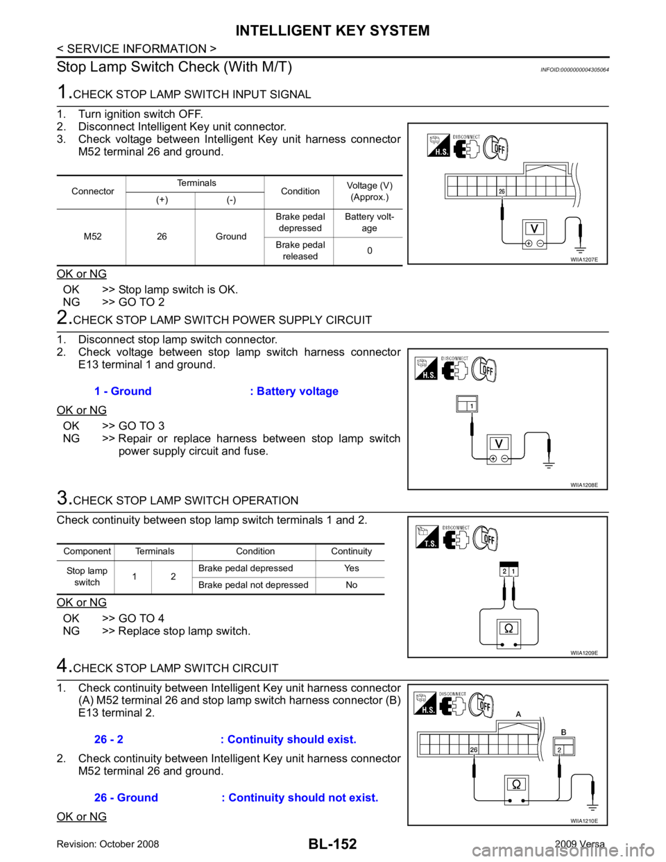
CHECK STOP LAMP SWITCH INPUT SIGNAL
1. Turn ignition switch OFF.
2. Disconnect Intelligent Key unit connector.
3. Check voltage between Intelligent Key unit harness connector M52 terminal 26 and ground.
OK or NG OK >> Stop lamp switch is OK.
NG >> GO TO 2 2.
CHECK STOP LAMP SWIT CH POWER SUPPLY CIRCUIT
1. Disconnect stop lamp switch connector.
2. Check voltage between stop lamp switch harness connector
E13 terminal 1 and ground.
OK or NG OK >> GO TO 3
NG >> Repair or replace harness between stop lamp switch power supply circuit and fuse. 3.
CHECK STOP LAMP SWITCH OPERATION
Check continuity between stop lamp switch terminals 1 and 2.
OK or NG OK >> GO TO 4
NG >> Replace stop lamp switch. 4.
CHECK STOP LAMP SWITCH CIRCUIT
1. Check continuity between Inte lligent Key unit harness connector
(A) M52 terminal 26 and stop lamp switch harness connector (B)
E13 terminal 2.
2. Check continuity between Inte lligent Key unit harness connector
M52 terminal 26 and ground.
OK or NG Connector
Terminals
ConditionVoltage (V)
(Approx.)
(+) (-)
M52 26 Ground Brake pedal
depressed Battery volt-
age
Brake pedal released 0 WIIA1207E
1 - Ground : Battery voltage
WIIA1208E
Component Terminals Condition Continuity
Stop lamp switch 1 2 Brake pedal depressed Yes
Brake pedal not depressed No WIIA1209E
26 - 2 : Continuity should exist.
26 - Ground : Continuity should not exist. WIIA1210E
Page 644 of 4331
BACK DOOR LOCK
BL-183
< SERVICE INFORMATION >
C
D E
F
G H
J
K L
M A
B BL
N
O P
OK >> GO TO 2.
NG >> If fuse is blown, be sure to eliminate caus e of malfunction before installing new fuse. Refer to PG-3, " Schematic " .
2.
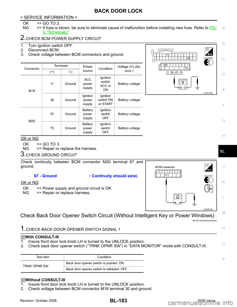
CHECK BCM POWER SUPPLY CIRCUIT
1. Turn ignition switch OFF.
2. Disconnect BCM.
3. Check voltage between BCM connectors and ground.
OK or NG OK >> GO TO 3.
NG >> Repair or replace the harness. 3.
CHECK GROUND CIRCUIT
Check continuity between BCM connector M20 terminal 67 and
ground.
OK or NG OK >> Power supply and ground circuit is OK.
NG >> Repair or replace harness.
Check Back Door Opener S witch Circuit (Without Intellig ent Key or Power Windows)
INFOID:00000000043050921.
CHECK BACK DOOR OPENER SWITCH SIGNAL 1
With CONSULT-III
1. Insure front door lock knob LH is turned to the UNLOCK position.
2. Check back door opener switch (“TRNK OPNR SW ”) in “DATA MONITOR” mode with CONSULT-III.
Without CONSULT-III
1. Insure front door lock knob LH is turned to the UNLOCK position.
2. Check voltage between BCM connector M18 terminal 30 and ground. Connector
Terminals
Power
source Condition Voltage (V) (Ap-
prox.)
(+) (-)
M18 11 Ground
ACC
power
supply Ignition
switch
ACC or ON Battery voltage
38 Ground Ignition
power
supply Ignition
switch ON
or START Battery voltage
M20 57 Ground
Battery
power
supply Ignition
switch OFF Battery voltage
70 Ground Battery
power
supply Ignition
switch OFF Battery voltage LIIA2415E
67 - Ground : Continuity should exist.
LIIA0915E
Test item Condition
TRNK OPNR SW Back door opener switch is pushed: ON
Back door opener switch is released: OFF
Page 668 of 4331
TRUNK LID OPENER
BL-207
< SERVICE INFORMATION >
C
D E
F
G H
J
K L
M A
B BL
N
O P
OK >> GO TO 2.
NG >> If fuse is blown, be sure to eliminate caus e of malfunction before installing new fuse. Refer to PG-3, " Schematic " .
2.
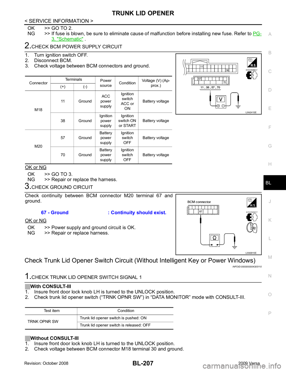
CHECK BCM POWER SUPPLY CIRCUIT
1. Turn ignition switch OFF.
2. Disconnect BCM.
3. Check voltage between BCM connectors and ground.
OK or NG OK >> GO TO 3.
NG >> Repair or replace the harness. 3.
CHECK GROUND CIRCUIT
Check continuity between BCM connector M20 terminal 67 and
ground.
OK or NG OK >> Power supply and ground circuit is OK.
NG >> Repair or replace harness.
Check Trunk Lid Opener Switch Circuit (Wit hout Intelligent Key or Power Windows)
INFOID:00000000043051101.
CHECK TRUNK LID OPENER SWITCH SIGNAL 1
With CONSULT-III
1. Insure front door lock knob LH is turned to the UNLOCK position.
2. Check trunk lid opener switch (“TRNK OPNR SW”) in “DATA MONITOR” mode with CONSULT-III.
Without CONSULT-III
1. Insure front door lock knob LH is turned to the UNLOCK position.
2. Check voltage between BCM connector M18 terminal 30 and ground. Connector
Terminals
Power
source Condition Voltage (V) (Ap-
prox.)
(+) (-)
M18 11 Ground
ACC
power
supply Ignition
switch
ACC or ON Battery voltage
38 Ground Ignition
power
supply Ignition
switch ON
or START Battery voltage
M20 57 Ground
Battery
power
supply Ignition
switch OFF Battery voltage
70 Ground Battery
power
supply Ignition
switch OFF Battery voltage LIIA2415E
67 - Ground : Continuity should exist.
LIIA0915E
Test item Condition
TRNK OPNR SW Trunk lid opener switch is pushed: ON
Trunk lid opener switch is released: OFF