Page 4160 of 4331
![NISSAN LATIO 2009 Service Repair Manual OK >> GO TO "WORK FLOW" .
NG >> Check the following.
• 10A fuse [No. 3, located in fuse block (J/B)]
• CHARGE lamp
• Harness for open or short between combination meter and fuse
• Harness for NISSAN LATIO 2009 Service Repair Manual OK >> GO TO "WORK FLOW" .
NG >> Check the following.
• 10A fuse [No. 3, located in fuse block (J/B)]
• CHARGE lamp
• Harness for open or short between combination meter and fuse
• Harness for](/manual-img/5/57359/w960_57359-4159.png)
OK >> GO TO "WORK FLOW" .
NG >> Check the following.
• 10A fuse [No. 3, located in fuse block (J/B)]
• CHARGE lamp
• Harness for open or short between combination meter and fuse
• Harness for open or short between combination meter and generator
DIAGNOSTIC PROCEDURE 2
Check Battery Circuit OK >> GO TO 2.
NG >> Repair terminal 1 connection. Confirm repair by performing complete Starting/Charging system
test. Refer to diagnostic station instruction manual. OK >> GO TO 3.
NG >> Check the following. • 120A fusible link [letter a , located in fusible link box
(battery)]
• Harness for open or short between generator and fus- ible link OK >> Replace the generator. Refer to
SC-25, " Removal and
Installation " . Confirm repair by performing complete
Starting/Charging system test. Refer to diagnostic sta-
tion instruction manual.
NG >> Check harness between the battery and the generator for poor continuity.
DIAGNOSTIC PROCEDURE 3
Check Voltage Regulator Circuit CHARGE lamp should light up.
B
Page 4161 of 4331
SC
N
O P OK >> GO TO 2.
NG >> Repair terminal 3 connection. Confirm repair by performing complete Starting/Charging system
test. Refer to diagnostic station instruction manual. OK >> GO TO 3.
NG >> Check the following.
• 10A fuse (No. 29, located in fuse and fusible link box)
• Harness for open or short between generator and fuse OK >> Replace the generator. Refer to
SC-25, " Removal and
Installation " . Confirm repair by performing complete
Starting/Charging system test. Refer to diagnostic sta-
tion instruction manual.
NG >> Check harness between the battery and the generator for poor continuity.
Removal and Installation INFOID:0000000004306828
Battery voltage should exist.
Page 4198 of 4331
How to Handle Battery " .)
• Fuses (Refer to SRS-11, " Schematic " .)
• System component-to-harness connections
WORK FLOW User mode Diagnosis mode Display type
“AIR BAG” warning lamp X X ON-OFF operation CONSULT-III — X Monitoring
Page 4254 of 4331
EPS Terminal and Reference Value " .
DIAGNOSTIC PROCEDURE OK >> GO TO 2.
NG >> Check the following. If any items are damaged, repair or replace damaged parts. • 60 A fusible link (No. m, located in the fuse and fusible link block). Refer to PG-3 .
• 10 A fuse [No. 2, located in the fuse block (J/B)]. Refer to PG-3 .
• Harness for short or open between battery and EPS control unit harness connector M54 termi-
nal 17.
• Harness for short or open between ignition switch and EPS control unit harness connector M53
terminal 10. Connector Terminal Voltage
M53 10 – Ground Battery voltage
M54 17 – Ground Battery voltage
Page 4262 of 4331
![NISSAN LATIO 2009 Service Repair Manual STC-22< SERVICE INFORMATION >
[EPS]
TROUBLE DIAGNOSIS FOR SYMPTOMS
5. Turn ignition switch “OFF”.
6. Check voltage between EPS control unit harness connector (A) terminals and ground.
7. Connect E NISSAN LATIO 2009 Service Repair Manual STC-22< SERVICE INFORMATION >
[EPS]
TROUBLE DIAGNOSIS FOR SYMPTOMS
5. Turn ignition switch “OFF”.
6. Check voltage between EPS control unit harness connector (A) terminals and ground.
7. Connect E](/manual-img/5/57359/w960_57359-4261.png)
STC-22< SERVICE INFORMATION >
[EPS]
TROUBLE DIAGNOSIS FOR SYMPTOMS
5. Turn ignition switch “OFF”.
6. Check voltage between EPS control unit harness connector (A) terminals and ground.
7. Connect EPS control unit harness connector.
OK or NG OK >> GO TO 3.
NG >> Check the following. If any items are damaged, repair or replace damaged parts.
• 60 A fusible link (No. m, located in the fuse and fusible link block). Refer to PG-3 .
• 10 A fuse [No. 2, located in the fuse block (J/B)]. Refer to PG-3 .
• Harness for short or open between battery and EPS control unit harness connector M54 termi-
nal 17.
• Harness for short or open between ignition switch and EPS control unit harness connector M53 terminal 10. 3.
CHECK EPS CONTROL UNIT GROUND CIRCUIT
1. Turn ignition switch “OFF”.
2. Disconnect EPS control unit harness connector.
3. Check continuity between EP S control unit harness connector
(A) terminal and ground.
Also check harness for short to power.
4. Connect EPS control unit harness connector.
OK or NG OK >> GO TO 4.
NG >> Repair open circuit or short to ground or short to power in harness or connectors. 4.
CHECK EPS CONTROL UNIT
Check EPS control unit input/output signal. Refer to STC-9, " EPS Control Unit Input/Output Signal Reference
Value " .
OK or NG OK >> GO TO 5.
NG >> Check EPS control unit pin terminals for dam age or loose connection with harness connector. If
any items are damaged, repair or replace damaged parts. 5.
SYMPTOM CHECK
Check again.
OK or NG OK >>
INSPECTION END
NG >> Replace combination meter. Refer to DI-19, " Removal and Installation " .
Steering Wheel Turning Fo rce Is Heavy or Light INFOID:0000000004307309
SYMPTOM:
Steering wheel turning force is heavy or light, while driving.
DIAGNOSTIC PROCEDURE 1.
CHECK SYSTEM FOR CAN COMMUNICATION LINE
Perform self-diagnosis. Refer to STC-11, " CONSULT-III F
unction (EPS) " .
Connector Terminal Voltage
M53 10 – Ground Approx. 0 V
M54 17 – Ground Battery voltage SGIA1627E
Connector Terminal Continuity
M54 18 YES SGIA1628E
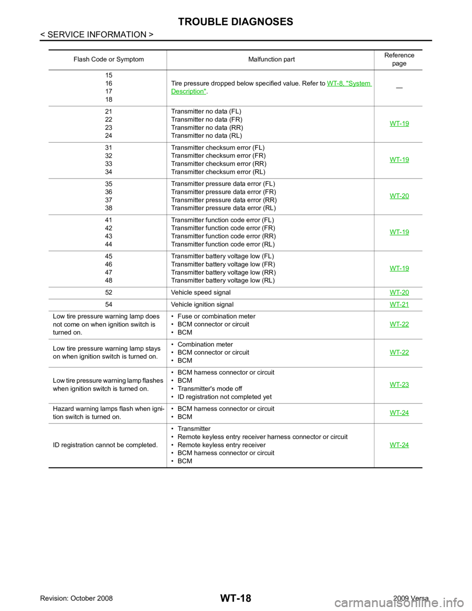
Page 4283 of 4331

System
Description " .
—
21
22
23
24 Transmitter no data (FL)
Transmitter no data (FR)
Transmitter no data (RR)
Transmitter no data (RL) WT-1931
32
33
34 Transmitter chec
ksum error (FL)
Transmitter chec ksum error (FR)
Transmitter chec ksum error (RR)
Transmitter chec ksum error (RL) WT-1935
36
37
38 Transmitter pressure
data error (FL)
Transmitter pressure data error (FR)
Transmitter pressure data error (RR)
Transmitter pressure data error (RL) WT-2041
42
43
44 Transmitter function
code error (FL)
Transmitter function code error (FR)
Transmitter function code error (RR)
Transmitter function code error (RL) WT-1945
46
47
48 Transmitter battery voltage low (FL)
Transmitter battery voltage low (FR)
Transmitter battery voltage low (RR)
Transmitter battery voltage low (RL) WT-1952 Vehicle speed signal
WT-2054 Vehicle ignition signal
WT-21Low tire pressure warning lamp does
not come on when ignition switch is
turned on. • Fuse or combination meter
• BCM connector or circuit
• BCM WT-22Low tire pressure
warning lamp stays
on when ignition switch is turned on. • Combination meter
• BCM connector or circuit
• BCM WT-22Low tire pressure wa
rning lamp flashes
when ignition switch is turned on. • BCM harness connector or circuit
• BCM
• Transmitter's mode off
• ID registration not completed yet WT-23Hazard warning lamps flash when igni-
tion switch is turned on. • BCM harness connector or circuit
• BCM WT-24ID registration cannot be completed.
• Transmitter
• Remote keyless entry receiver harness connector or circuit
• Remote keyless entry receiver
• BCM harness connector or circuit
• BCM WT-24
Page 4295 of 4331

WW
N
O P
FRONT WIPER AND WASHER SYSTEM
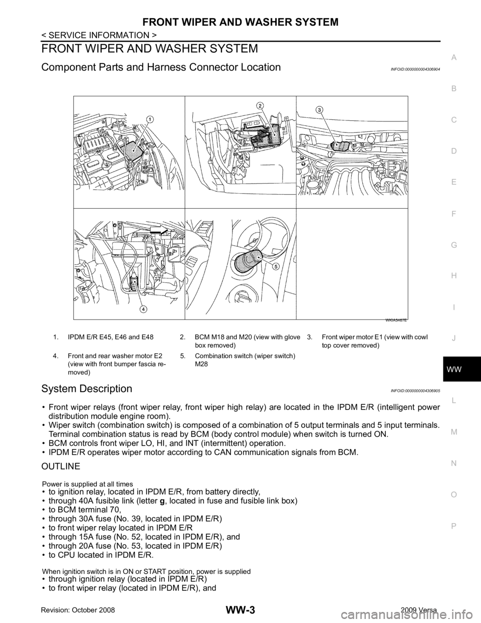
Component Parts and Har ness Connector Location INFOID:0000000004306904
System Description INFOID:0000000004306905
• Front wiper relays (front wiper relay, front wiper hi gh relay) are located in the IPDM E/R (intelligent power
distribution module engine room).
• Wiper switch (combination switch) is composed of a combination of 5 output terminals and 5 input terminals.
Terminal combination status is read by BCM (body control module) when switch is turned ON.
• BCM controls front wiper LO, HI, and INT (intermittent) operation.
• IPDM E/R operates wiper motor accordi ng to CAN communication signals from BCM.
OUTLINE
Power is supplied at all times
• to ignition relay, located in IPDM E/R, from battery directly,
• through 40A fusible link (letter g, located in fuse and fusible link box)
• to BCM terminal 70,
• through 30A fuse (No. 39, located in IPDM E/R)
• to front wiper relay located in IPDM E/R
• through 15A fuse (No. 52, located in IPDM E/R), and
• through 20A fuse (No. 53, located in IPDM E/R)
• to CPU located in IPDM E/R.
When ignition switch is in ON or START position, power is supplied
• through ignition relay (located in IPDM E/R)
• to front wiper relay (located in IPDM E/R), and 1. IPDM E/R E45, E46 and E48 2. BCM M18 and M20 (view with glove
box removed)3. Front wiper motor E1
(view with cowl
top cover removed)
4. Front and rear washer motor E2 (view with front bumper fascia re-
moved) 5. Combination switch (wiper switch)
M28
Page 4317 of 4331

WW
N
O P
REAR WIPER AND WASHER SYSTEM
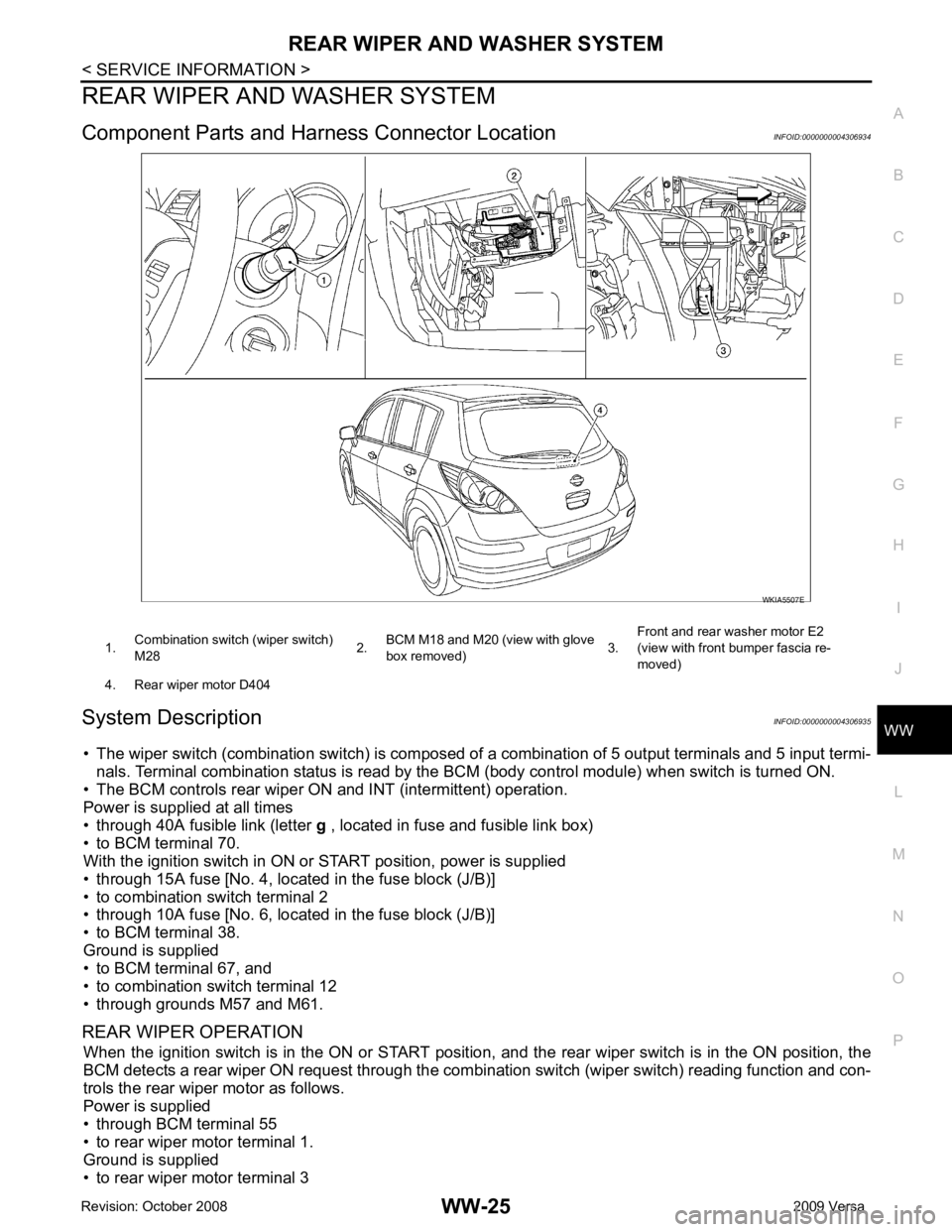
Component Parts and Har ness Connector Location INFOID:0000000004306934
System Description INFOID:0000000004306935
• The wiper switch (combination switch ) is composed of a combination of 5 output terminals and 5 input termi-
nals. Terminal combination status is read by the BCM (body control module) when switch is turned ON.
• The BCM controls rear wiper ON and INT (intermittent) operation.
Power is supplied at all times
• through 40A fusible link (letter g , located in fuse and fusible link box)
• to BCM terminal 70.
With the ignition switch in ON or START position, power is supplied
• through 15A fuse [No. 4, located in the fuse block (J/B)]
• to combination switch terminal 2
• through 10A fuse [No. 6, located in the fuse block (J/B)]
• to BCM terminal 38.
Ground is supplied
• to BCM terminal 67, and
• to combination switch terminal 12
• through grounds M57 and M61.
REAR WIPER OPERATION When the ignition switch is in the ON or START position, and the rear wiper switch is in the ON position, the
BCM detects a rear wiper ON request through the combi nation switch (wiper switch) reading function and con-
trols the rear wiper motor as follows.
Power is supplied
• through BCM terminal 55
• to rear wiper motor terminal 1.
Ground is supplied
• to rear wiper motor terminal 3