2009 NISSAN LATIO fuse
[x] Cancel search: fusePage 3699 of 4331

LT
N
O P
• to map lamp terminal 1
Power is supplied
• through BCM terminal 56
• to map lamp terminal 4.
When interior room lamp switch is ON, ground is supplied
• to interior room lamp terminal 1
• through map lamp (with map lamp) terminal 7
• through map lamp (with map lamp) terminal 1
• through grounds M57 and M61.
Power is supplied
• through BCM terminal 56
• through map lamp (with map lamp) terminal 4
• through map lamp (with map lamp) terminal 6
• to room lamp terminal 3.
INTERIOR ROOM LAMP TIMER OPERATION
Without Intelligent Key System When room lamp switch is in DOOR position, and w hen all conditions below are met, BCM performs timer
control (maximum 30 seconds) for room lamp ON/OFF.
In addition, when the interior room lamp turns ON or OFF there is gradual brightening or dimming over 1 sec-
ond.
Power is supplied
• through 10A fuse [No. 14, located in fuse block (J/B)]
• to key switch and key lock solenoid terminal 2.
When the key is removed from ignition key cylinder (key switch OFF), power will not be supplied to BCM termi-
nal 37.
When front door key cylinder switch LH is unlocked, ground is supplied
• to BCM terminal 7
• through front door key cylinder switch LH terminal 3
• through front door key cylinder switch LH terminal 2
• through grounds M57 and M61.
At the time that front door LH is opened, BCM detects that front door LH is unlocked. It determines that interior
room lamp timer operation condition is met, and turns the room lamp ON for 30 seconds.
When key is in ignition key cylinder (key switch ON),
Power is supplied
• through key switch and key lock solenoid terminal 1
• to BCM terminal 37.
When key is removed from key switch and key lock soleno id (key switch OFF), the power supply to BCM ter-
minal 37 is terminated. BCM detects that key has been re moved, determines that interior room lamp timer
conditions are met, and turns the room lamp ON for 30 seconds.
When front door LH opens → closes, and the key is not inserted in the key switch and key lock solenoid (key
switch OFF), voltage at BCM terminal 47 changes between 0V (door open) → 12V (door closed). The BCM
determines that conditions for room lamp operation are met and turns the room lamp ON for 30 seconds.
Interior room lamp timer control is canceled under the following conditions:
• Front door LH is locked (locked by front door key cylinder switch LH, keyfob or door lock/unlock switch).
• Front door LH is opened (front door switch LH).
• Ignition switch ON.
With Intelligent Key System When the room lamp switch is in DOOR position, and when all conditions below are met, BCM performs timer
control (maximum 30 second) for room lamp ON/OFF.
In addition, when interior room lamp turns ON or OFF there is gradual brightening or dimming over 1 second.
Power is supplied
• through 10A fuse (No. 31, located in fuse and fusible link box)
• to key switch and ignition knob switch terminals 2 and 4.
When key is removed from ignition key cylinder (key switch OFF), power will not be supplied to BCM terminal
37.
When the ignition knob switch is released, power wil l not be supplied to Intelligent Key unit terminal 27.
When front door key cylinder switch LH is unlocked, ground is supplied
• to BCM terminal 7
• through front door key cylinder switch LH terminal 3
Page 3713 of 4331

LT
N
O P
ILLUMINATION
System Description INFOID:0000000004306640
The control of the illumination lamps operation is dependent upon the position of the lighting switch. When the
lighting switch is placed in the 1ST or 2ND position, the BCM (body control module) receives input signal
requesting the illumination lamps to illuminate. This input signal is communicated to IPDM E/R (intelligent
power distribution module engine room) across CAN communication lines. CPU (central processing unit)
located in the IPDM E/R controls the tail lamp relay coil . This relay, when energized, directs power to the illu-
mination lamps, which then illuminate.
Power is supplied at all times
• to ignition relay, located in IPDM E/R,
• to tail lamp relay, located in IPDM E/R,
• through 15A fuse (No. 52, located in IPDM E/R) and
• through 20A fuse (No. 53, located in IPDM E/R)
• to CPU located in IPDM E/R,
• through 40A fusible link (letter g, located in fuse and fusible link box)
• to BCM terminal 70, and
• through 10A fuse [No. 8, located in fuse block (J/B)]
• to BCM terminal 57.
With the ignition switch in the ON or START position, power is supplied
• to ignition relay, located in IPDM E/R, and
• through 10A fuse [No. 6, located in fuse block (J/B)]
• to BCM terminal 38.
With the ignition switch in the ACC or ON position, power is supplied
• through 10A fuse [No. 20, located in fuse block (J/B)]
• to BCM terminal 11.
Ground is supplied
• to BCM terminal 67
• through grounds M57 and M61, and
• to IPDM E/R terminals 39 and 59
• through grounds E15 and E24.
ILLUMINATION OPERATION BY LIGHTING SWITCH With the lighting switch in the 1ST or 2ND positi on, BCM receives input signal requesting the illumination
lamps to illuminate. This input signal is communicat ed to IPDM E/R across CAN communication lines. CPU
located in the IPDM E/R controls the tail lamp relay coil, which, when energized, directs power
• through 10A fuse (No. 37, located in IPDM E/R)
• through IPDM E/R terminal 29
• to microphone terminal 3 (with Bluetooth)
• to illumination control switch terminal 1
• to glove box lamp terminal 1 (with glovebox lamp)
• to audio unit terminal 9
• to front air control terminal 5
• to A/T device terminal 3 (with 4-speed A/T)
• to CVT device terminal 3 (with CVT)
• to hazard switch terminal 3
• to combination meter terminal 12
• to door mirror remote control switch terminal 16
• to combination switch (spiral cable) terminal 26 (with steering wheel audio control switches)
• to steering wheel audio control switches through combinat ion switch (spiral cable) terminal 18 (with steering
wheel audio control switches).
Ground is supplied
• to microphone terminal 2 (with Bluetooth)
• to glove box lamp terminal 2 (with glove box lamp), and
• to illumination control switch terminal 3
• through grounds M57 and M61.
The illumination control switch controls illuminat ion intensity by varying the ground to the following
• through illumination control switch terminal 2
• to audio unit terminal 8
• to front air control terminal 6
Page 3920 of 4331
![NISSAN LATIO 2009 Service Repair Manual MTC
N
O P
NG >> Check power supply circuit and 15A fuses [Nos. 15 and 17, located in the fuse block (J/B)].
Refer to PG-3, " Schematic " .
• If fuses are OK, reinstall fuses and GO T NISSAN LATIO 2009 Service Repair Manual MTC
N
O P
NG >> Check power supply circuit and 15A fuses [Nos. 15 and 17, located in the fuse block (J/B)].
Refer to PG-3, " Schematic " .
• If fuses are OK, reinstall fuses and GO T](/manual-img/5/57359/w960_57359-3919.png)
MTC
N
O P
NG >> Check power supply circuit and 15A fuses [Nos. 15 and 17, located in the fuse block (J/B)].
Refer to PG-3, " Schematic " .
• If fuses are OK, reinstall fuses and GO TO 3.
• If fuses are NG, replace fuse and check harness for short circuit. Repair or replace if necessary. OK >> GO TO 4.
NG >> Repair harness or connector. OK >> GO TO 5.
NG >> Repair harness or connector. OK >> Replace blower motor relay.
NG >> Repair harness or connector. OK >> GO TO 7.
NG >> Replace front blower motor. Refer to MTC-62, " Removal
and Installation " .
Page 3923 of 4331

OK >> If the symptom still exists, perform
a complete operational check. Refer to MTC-30, " Operational
Check " . If other symptoms exist, refer to
MTC-22, " How to Perform Trouble Diagnosis for Quick
and Accurate Repair " .
NG >> Repair as necessary.
SYSTEM DESCRIPTION
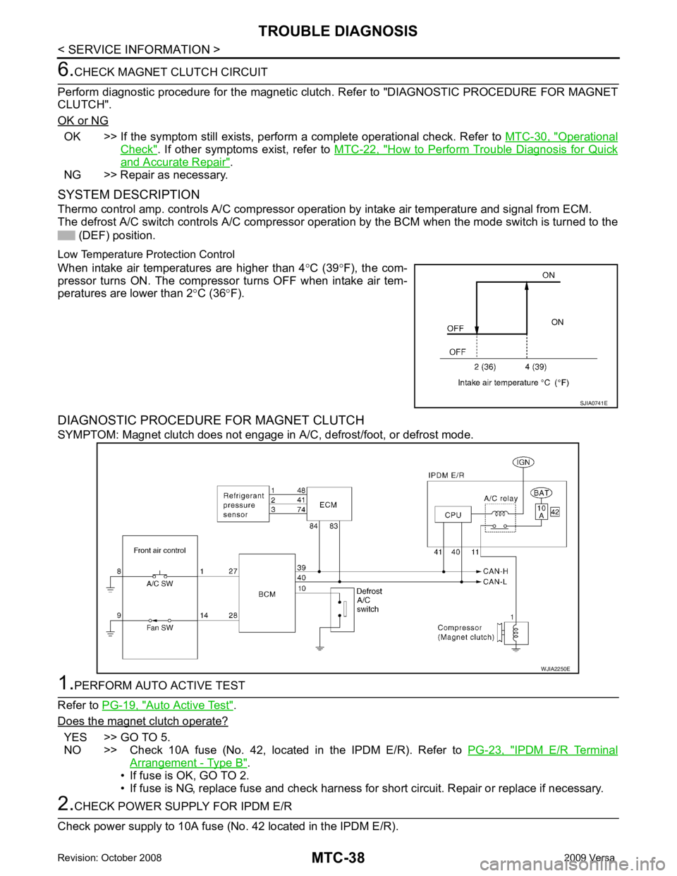
Thermo control amp. controls A/C compressor operat ion by intake air temperature and signal from ECM.
The defrost A/C switch controls A/ C compressor operation by the BCM when the mode switch is turned to the
(DEF) position.
Low Temperature Protection Control
When intake air temperatures are higher than 4 °C (39 °F), the com-
pressor turns ON. The compressor turns OFF when intake air tem-
peratures are lower than 2 °C (36 °F).
DIAGNOSTIC PROCEDURE FOR MAGNET CLUTCH
SYMPTOM: Magnet clutch does not engage in A/C, defrost/foot, or defrost mode.Auto Active Test " .
Does the magnet clutch operate? YES >> GO TO 5.
NO >> Check 10A fuse (No. 42, located in the IPDM E/R). Refer to PG-23, " IPDM E/R Terminal
Arrangement - Type B " .
• If fuse is OK, GO TO 2.
• If fuse is NG, replace fuse and check harness for short circuit. Repair or replace if necessary.
Page 3928 of 4331

MTC
N
O P
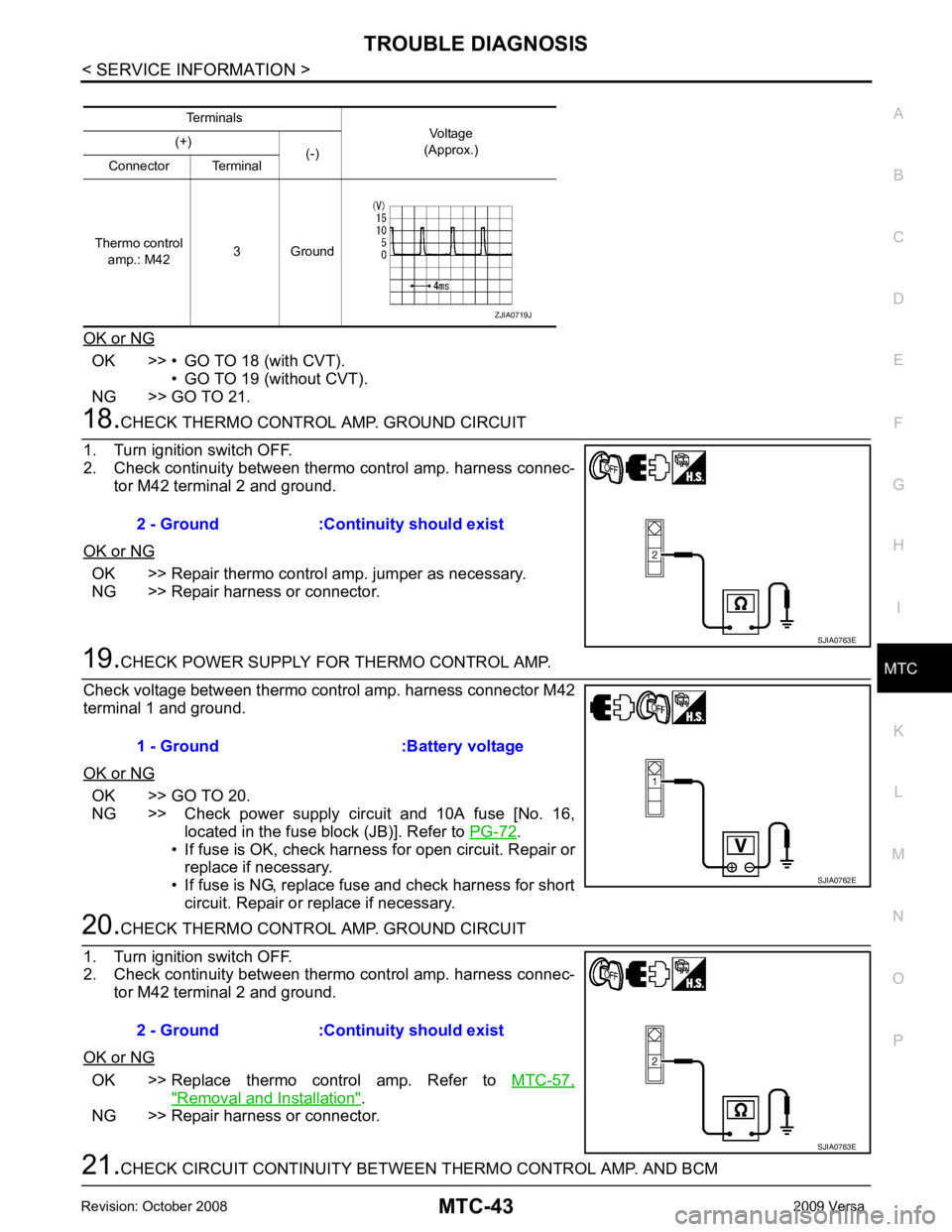
OK or NG OK >> • GO TO 18 (with CVT).
• GO TO 19 (without CVT).
NG >> GO TO 21. OK >> Repair thermo control amp. jumper as necessary.
NG >> Repair harness or connector. OK >> GO TO 20.
NG >> Check power supply circuit and 10A fuse [No. 16, located in the fuse block (JB)]. Refer to PG-72 .
• If fuse is OK, check harness for open circuit. Repair or
replace if necessary.
• If fuse is NG, replace fuse and check harness for short circuit. Repair or replace if necessary. OK >> Replace thermo control amp. Refer to
MTC-57," Removal and Installation " .
NG >> Repair harness or connector.
Page 3984 of 4331

PG
N
O P
CONTENTS
POWER SUPPLY, GROUND & CIRCUIT ELEMENTS
SERVICE INFORMATION .. ..........................2
PRECAUTIONS .............................................. .....2
Precaution for Supplemental Restraint System
(SRS) "AIR BAG" and "SEAT BELT PRE-TEN-
SIONER" ............................................................. ......
2
POWER SUPPLY ROUTING CIRCUIT .......... .....3
Schematic ........................................................... ......3
Wiring Diagram - POWER - ................................ ......5
Fuse .................................................................... ....15
Fusible Link ......................................................... ....15
Circuit Breaker (Built Into BCM) .......................... ....15
Circuit Breaker .................................................... ....15
IPDM E/R (INTELLIGENT POWER DISTRI-
BUTION MODULE ENGINE ROOM) ............. ....16
System Description ............................................. ....16
CAN Communication System Description ........... ....17
Function of Detecting Igni tion Relay Malfunction ....17
CONSULT-III Function (IPDM E/R) ..................... ....17
Auto Active Test .................................................. ....19
IPDM E/R Terminal Arrangement - Type A ......... ....22
IPDM E/R Terminal Arrangement - Type B ......... ....23
Terminal and Reference Value for IPDM E/R ..... ....24
IPDM E/R Power/Ground Circuit Inspection ....... ....26
Inspection with CONSULT- III (Self-Diagnosis) .......27
Removal and Installation of IPDM E/R ....................27 GROUND CIRCUI
T ........................................... 29
Ground Distribution .............................................. ....29
HARNESS ................... ...................................... 38
Harness Layout ................................................... ....38
Wiring Diagram Codes (Cell Codes) ................... ....57
ELECTRICAL UNITS LOCATION .................... 60
Electrical Units Location ...................................... ....60
HARNESS CONNECTOR ................................. 64
Description ........................................................... ....64
ELECTRICAL UNITS ........................................ 67
Terminal Arrangement ......................................... ....67
STANDARDIZED RELAY ................................. 68
Description ........................................................... ....68
SUPER MULTIPLE JUNCTION (SMJ) ............. 70
Terminal Arrangement ......................................... ....70
FUSE BLOCK-JUNCTION BOX (J/B) .............. 72
Terminal Arrangement ......................................... ....72
FUSE AND FUSIBLE LINK BOX ...................... 73
Terminal Arrangement ......................................... ....73
Page 3998 of 4331

PG
N
O P
Fuse
INFOID:0000000004306651
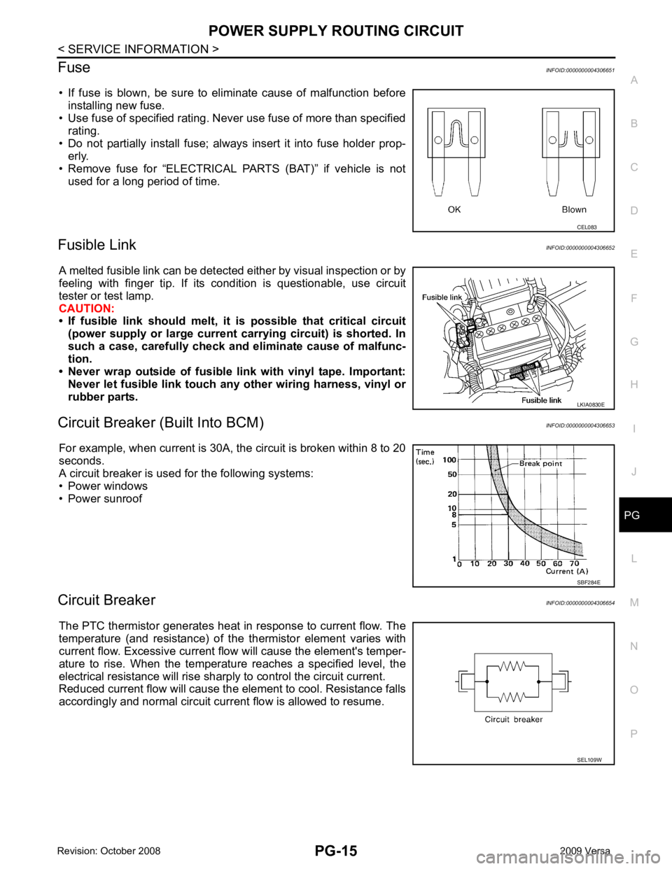
• If fuse is blown, be sure to eliminate cause of malfunction before installing new fuse.
• Use fuse of specified rating. Never use fuse of more than specified
rating.
• Do not partially install fuse; always insert it into fuse holder prop- erly.
• Remove fuse for “ELECTRICAL PARTS (BAT)” if vehicle is not
used for a long period of time.
Fusible Link INFOID:0000000004306652
A melted fusible link can be detected either by visual inspection or by
feeling with finger tip. If its condition is questionable, use circuit
tester or test lamp.
CAUTION:
• If fusible link should melt, it is possible that critical circuit
(power supply or large current carrying circuit) is shorted. In
such a case, carefully check and eliminate cause of malfunc-
tion.
• Never wrap outside of fusible li nk with vinyl tape. Important:
Never let fusible link touch any other wiring harness, vinyl or
rubber parts.
Circuit Breaker (B uilt Into BCM) INFOID:0000000004306653
For example, when current is 30A, the circuit is broken within 8 to 20
seconds.
A circuit breaker is used for the following systems:
• Power windows
• Power sunroof
Circuit Breaker INFOID:0000000004306654
The PTC thermistor generates heat in response to current flow. The
temperature (and resistance) of t he thermistor element varies with
current flow. Excessive current flow will cause the element's temper-
ature to rise. When the temperature reaches a specified level, the
electrical resistance will rise shar ply to control the circuit current.
Reduced current flow will cause the element to cool. Resistance falls
accordingly and normal circuit current flow is allowed to resume. LKIA0830E
SEL109W
Page 4006 of 4331

PG
N
O P
IPDM E/R Terminal Ar
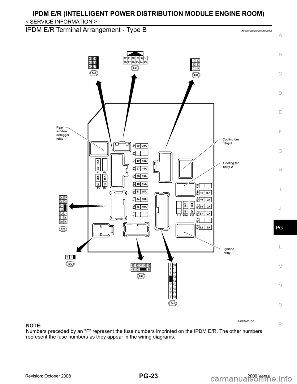
rangement - Type B INFOID:0000000004306660
NOTE:
Numbers preceded by an "F" represent the fuse number s imprinted on the IPDM E/R. The other numbers
represent the fuse numbers as they appear in the wiring diagrams.