Page 1809 of 1903
Downloaded from www.Manualslib.com manuals search engine The sunroof consists of the following components:
•Sunroof Frame (1)
• Windshield Frame (2)
• Sunroof Central Bracket (3)
• Sunroof Back Bracket (4)
• Rear Roof Frame (5)
• Head Liner (6)
• Sunroof Track (7)
• Sunroof Module (8)
• Sunroof Motor (9)
• Sunroof Deflector (10)
• Sunroof Glass (11)
• Guiding Gutter (12)
• Sun Visor (13)
Operation
The sunroof control module monitors the sunroof switch input. The sunroof control module controls the output of the
sunroof motor, to move the sunroof glass to the requested position. The power sunroof will operate with the ignition
switch turned to ON.
SUNROOF
15
15–225Chery Automobile Co., Ltd.
Page 1810 of 1903
Downloaded from www.Manualslib.com manuals search engine Electrical Schematics
Sunroof (Page 1 of 2)
SUNROOF
LTSMW150033T
15–226Chery Automobile Co., Ltd.
Page 1811 of 1903
Downloaded from www.Manualslib.com manuals search engine Sunroof (Page 2 of 2)
SUNROOF
LTSMW150034T
15
15–227Chery Automobile Co., Ltd.
Page 1812 of 1903

Downloaded from www.Manualslib.com manuals search engine DIAGNOSIS & TESTING
Sunroof Memory Relearn
Sunroof Memory Loss
The sunroof should be initialized if any of the following conditions occur:
(1) Sunroof Power Failure
•If power is lost during the operation of sunroof (the Sunroof Control Module will record a malfunction) and the
sunroof will need to be initialized.
• If power is lost within five seconds after normal operation has stopped, the Sunroof Control Module will not
have enough time to store parameters, and the sunroof will need to be initialized.
(2) Sunroof Mechanical Failure
• If after the sunroof has been used for a period of time, and can not be closed in position (there is a gap
between mechanical components). The time is generally about 2 years before the sunroof will need to be initial-
ized.
Sunroof Initialization Steps
•When the sunroof is closed, press and hold the open switch until the sunroof is completely opened, keep
pressing the switch for five seconds, then release the switch.
• Press and hold the sunroof close switch within two seconds until the sunroof is completely closed, keep press-
ing the switch for five seconds, then release the switch.
15–228Chery Automobile Co., Ltd.
Page 1813 of 1903

Downloaded from www.Manualslib.com manuals search engine ON-VEHICLE SERVICE
Sunroof Glass
Removal & Installation
1. Operate the sunroof switch to lift the sunroof to the full tilt position.
2. Push the inner trim strip (side cover inner LH/RH) rearwards to remove.
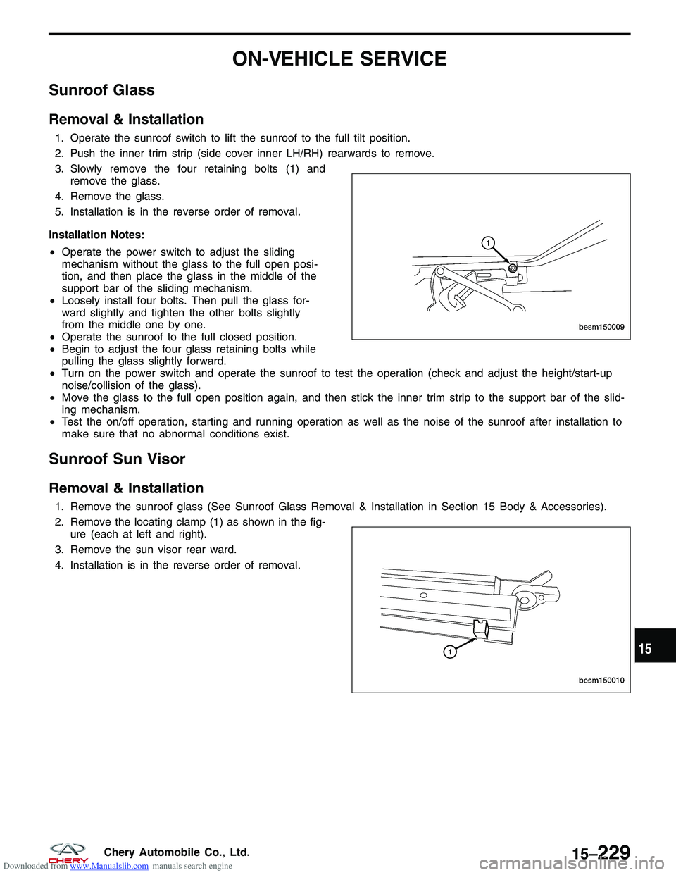
3. Slowly remove the four retaining bolts (1) andremove the glass.
4. Remove the glass.
5. Installation is in the reverse order of removal.
Installation Notes:
• Operate the power switch to adjust the sliding
mechanism without the glass to the full open posi-
tion, and then place the glass in the middle of the
support bar of the sliding mechanism.
• Loosely install four bolts. Then pull the glass for-
ward slightly and tighten the other bolts slightly
from the middle one by one.
• Operate the sunroof to the full closed position.
• Begin to adjust the four glass retaining bolts while
pulling the glass slightly forward.
• Turn on the power switch and operate the sunroof to test the operation (check and adjust the height/start-up
noise/collision of the glass).
• Move the glass to the full open position again, and then stick the inner trim strip to the support bar of the slid-
ing mechanism.
• Test the on/off operation, starting and running operation as well as the noise of the sunroof after installation to
make sure that no abnormal conditions exist.
Sunroof Sun Visor
Removal & Installation
1. Remove the sunroof glass (See Sunroof Glass Removal & Installation in Section 15 Body & Accessories).
2. Remove the locating clamp (1) as shown in the fig-
ure (each at left and right).
3. Remove the sun visor rear ward.
4. Installation is in the reverse order of removal.
BESM150009
BESM150010
15
15–229Chery Automobile Co., Ltd.
Page 1814 of 1903

Downloaded from www.Manualslib.com manuals search engine Sunroof Motor
Removal & Installation
1. Operate the sunroof to the full closed position before disassembling.
2. Remove the roof interior trim/ceiling light.
3. Disconnect the sunroof motor electrical connector and the wiring harness between the sunroof motor and thesunroof control module, and then cut off the band retaining the motor electrical harness.
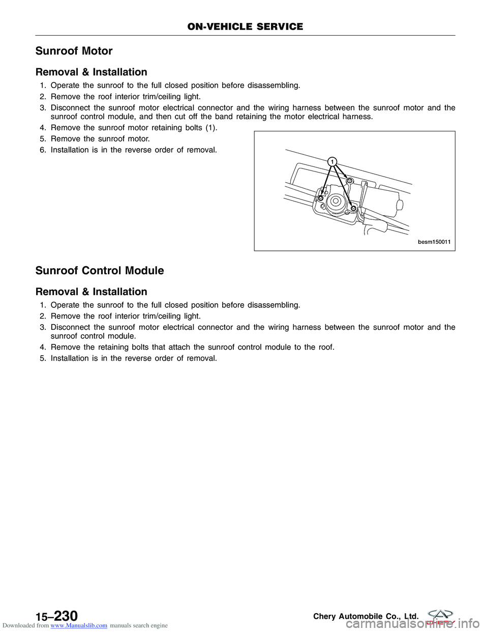
4. Remove the sunroof motor retaining bolts (1).
5. Remove the sunroof motor.
6. Installation is in the reverse order of removal.
Sunroof Control Module
Removal & Installation
1. Operate the sunroof to the full closed position before disassembling.
2. Remove the roof interior trim/ceiling light.
3. Disconnect the sunroof motor electrical connector and the wiring harness between the sunroof motor and the sunroof control module.
4. Remove the retaining bolts that attach the sunroof control module to the roof.
5. Installation is in the reverse order of removal.
ON-VEHICLE SERVICE
BESM150011
15–230Chery Automobile Co., Ltd.
Page 1815 of 1903
Downloaded from www.Manualslib.com manuals search engine WEATHERSTRIP
Front Door Weatherstrip
Removal & Installation
1. Remove the door trim panel (See Front Door Disassembly & Assembly in Section 15 Body & Accessories).
2. Remove the front door weatherstrip (1).
3. Installation is in the reverse order of removal.
Installation Notes:
• During the weatherstrip installation, every corner should be fitted in place with no folds. The joint of the weath-
erstrip should be placed in the lower middle of the door opening. The weatherstrip should have a proper rigidity
and should not interfere with the opening and closing of the door after the lock and hinge have been adjusted.
The surface of the assembled rubber strip should not have any defects such as deformation and warp.
LTSM150147
15
15–231Chery Automobile Co., Ltd.
Page 1816 of 1903
Downloaded from www.Manualslib.com manuals search engine Rear Door Weatherstrip
Removal & Installation
1. Remove the rear door weatherstrip (1).
2. Installation is in the reverse order of removal.
Installation Notes:
• During the weatherstrip installation, every corner
should be fitted in place with no folds. The joint of
the weatherstrip should be placed in the lower mid-
dle of the door opening. The weatherstrip should
have a proper rigidity and should not interfere with
the opening and closing of the door after the lock
and hinge have been adjusted. The surface of the
assembled rubber strip should not have any defects
such as deformation and warp.
WEATHERSTRIP
LTSM150148
15–232Chery Automobile Co., Ltd.