2008 NISSAN TIIDA Engine timing
[x] Cancel search: Engine timingPage 46 of 2771

AT-34
< SERVICE INFORMATION >
A/T CONTROL SYSTEM
Control Valve
INFOID:0000000001703170
FUNCTION OF CONTROL VALVES
Centrifugal Cancel MechanismINFOID:0000000001703171
FUNCTION
The centrifugal cancel mechanism is a mechanism to cancel the centrifugal hydraulic pressure instead of the
conventional check balls. It cancels the centrifugal hydraulic pressure which is generated as high clutch drum
rotates, and it allows for preventing high clutch from dragging and for providing stable high clutch piston press-
ing force in all revolution speeds.
STRUCTURE/OPERATION
Valve name Function
Pressure regulator valve, plug and sleeve
plugRegulates oil discharged from the oil pump to provide optimum line pressure for all driving
conditions.
Pressure modifier valve and sleeve Used as a signal supplementary valve to the pressure regulator valve. Regulates pres-
sure-modifier pressure (signal pressure) which controls optimum line pressure for all driv-
ing conditions.
Pilot valve Regulates line pressure to maintain a constant pilot pressure level which controls lock-up
mechanism, overrun clutch, shift timing.
Accumulator control valve Regulates accumulator back-pressure to pressure suited to driving conditions.
Manual valve Directs line pressure to oil circuits corresponding to select positions.
Hydraulic pressure drains when the shift lever is in Neutral.
Shift valve A Simultaneously switches three oil circuits using output pressure of shift solenoid valve A
to meet driving conditions (vehicle speed, throttle opening, etc.).
Provides automatic downshifting and upshifting (1st → 2nd → 3rd → 4th gears/4th → 3rd
→ 2nd → 1st gears) in combination with shift valve B.
Shift valve B Simultaneously switches two oil circuits using output pressure of shift solenoid valve B in
relation to driving conditions (vehicle speed, throttle opening, etc.).
Provides automatic downshifting and upshifting (1st → 2nd → 3rd → 4th gears/4th → 3rd
→ 2nd → 1st gears) in combination with shift valve A.
Overrun clutch control valve Switches hydraulic circuits to prevent engagement of the overrun clutch simultaneously
with application of the brake band in D
4. (Interlocking occurs if the overrun clutch engages
during D
4.)
1st reducing valve Reduces low & reverse brake pressure to dampen engine-brake shock when downshift-
ing from the 1st position 1
2 to 11.
Overrun clutch reducing valve Reduces oil pressure directed to the overrun clutch and prevents engine-brake shock.
In the 1st and 2nd positions, line pressure acts on the overrun clutch reducing valve to
increase the pressure-regulating point, with resultant engine brake capability.
Torque converter relief valve Prevents an excessive rise in torque converter pressure.
Torque converter clutch control valve, plug
and sleeveActivates or inactivates the lock-up function.
Also provides smooth lock-up through transient application and release of the lock-up
system.
1-2 accumulator valve and piston Lessens the shock find when the 2nd gear band servo contracts, and provides smooth
shifting.
3-2 timing valve Switches the pace that oil pressure is released depending on vehicle speed; maximizes
the high clutch release timing, and allows for soft downshifting.
Shuttle valve Determines if the overrun clutch solenoid valve should control the 3-2 timing valve or the
overrun clutch control valve and switches between the two.
Cooler check valve At low speeds and with a small load when a little heat is generated, saves the volume of
cooler flow, and stores the oil pressure for lock-up.
Page 75 of 2771
TROUBLE DIAGNOSIS
AT-63
< SERVICE INFORMATION >
D
E
F
G
H
I
J
K
L
MA
B
AT
N
O
P
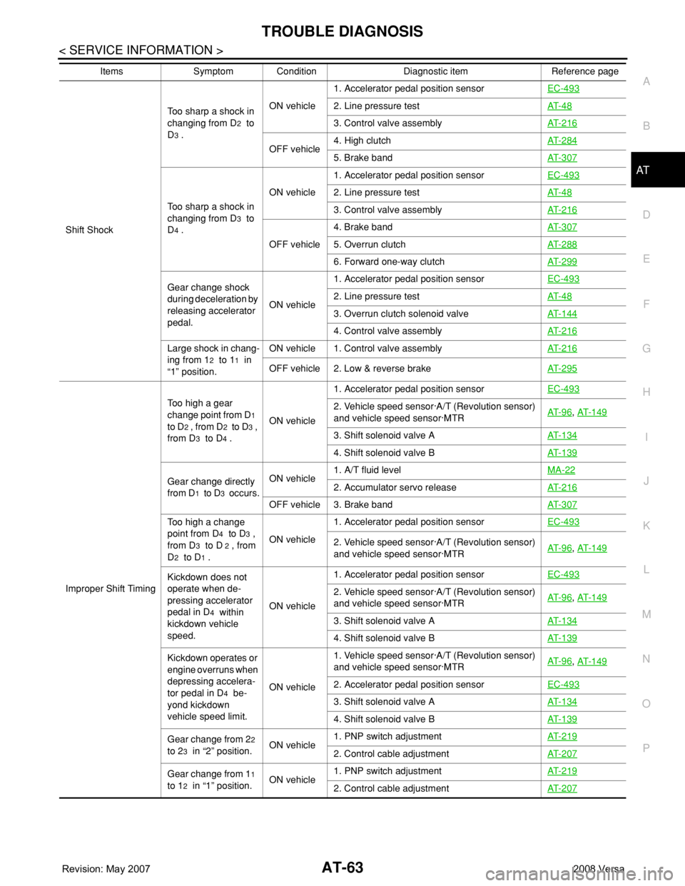
Shift ShockToo sharp a shock in
changing from D
2 to
D
3 .ON vehicle1. Accelerator pedal position sensorEC-493
2. Line pressure testAT- 4 8
3. Control valve assemblyAT- 2 1 6
OFF vehicle4. High clutchAT- 2 8 45. Brake bandAT- 3 0 7
Too sharp a shock in
changing from D
3 to
D
4 .ON vehicle1. Accelerator pedal position sensorEC-493
2. Line pressure testAT- 4 8
3. Control valve assemblyAT- 2 1 6
OFF vehicle4. Brake bandAT- 3 0 75. Overrun clutchAT- 2 8 8
6. Forward one-way clutchAT- 2 9 9
Gear change shock
during deceleration by
releasing accelerator
pedal.ON vehicle1. Accelerator pedal position sensorEC-4932. Line pressure testAT- 4 8
3. Overrun clutch solenoid valveAT- 1 4 4
4. Control valve assemblyAT- 2 1 6
Large shock in chang-
ing from 1
2 to 11 in
“1” position.ON vehicle 1. Control valve assemblyAT- 2 1 6OFF vehicle 2. Low & reverse brakeAT- 2 9 5
Improper Shift TimingToo high a gear
change point from D
1
to D
2 , from D2 to D3 ,
from D
3 to D4 .ON vehicle1. Accelerator pedal position sensorEC-493
2. Vehicle speed sensor·A/T (Revolution sensor)
and vehicle speed sensor·MTRAT- 9 6, AT- 1 4 9
3. Shift solenoid valve AAT- 1 3 4
4. Shift solenoid valve BAT- 1 3 9
Gear change directly
from D
1 to D3 occurs.ON vehicle1. A/T fluid levelMA-222. Accumulator servo releaseAT- 2 1 6
OFF vehicle 3. Brake bandAT- 3 0 7
Too high a change
point from D
4 to D3 ,
from D
3 to D 2 , from
D
2 to D1 .ON vehicle1. Accelerator pedal position sensorEC-493
2. Vehicle speed sensor·A/T (Revolution sensor)
and vehicle speed sensor·MTRAT- 9 6, AT- 1 4 9
Kickdown does not
operate when de-
pressing accelerator
pedal in D
4 within
kickdown vehicle
speed.ON vehicle1. Accelerator pedal position sensorEC-493
2. Vehicle speed sensor·A/T (Revolution sensor)
and vehicle speed sensor·MTRAT- 9 6, AT- 1 4 9
3. Shift solenoid valve AAT- 1 3 4
4. Shift solenoid valve BAT- 1 3 9
Kickdown operates or
engine overruns when
depressing accelera-
tor pedal in D
4 be-
yond kickdown
vehicle speed limit.ON vehicle1. Vehicle speed sensor·A/T (Revolution sensor)
and vehicle speed sensor·MTRAT- 9 6
, AT- 1 4 9
2. Accelerator pedal position sensorEC-493
3. Shift solenoid valve AAT- 1 3 4
4. Shift solenoid valve BAT- 1 3 9
Gear change from 22
to 2
3 in “2” position.ON vehicle1. PNP switch adjustmentAT- 2 1 92. Control cable adjustmentAT- 2 0 7
Gear change from 11
to 1
2 in “1” position.ON vehicle1. PNP switch adjustmentAT- 2 1 92. Control cable adjustmentAT- 2 0 7
Items Symptom Condition Diagnostic item Reference page
Page 85 of 2771
TROUBLE DIAGNOSIS
AT-73
< SERVICE INFORMATION >
D
E
F
G
H
I
J
K
L
MA
B
AT
N
O
P
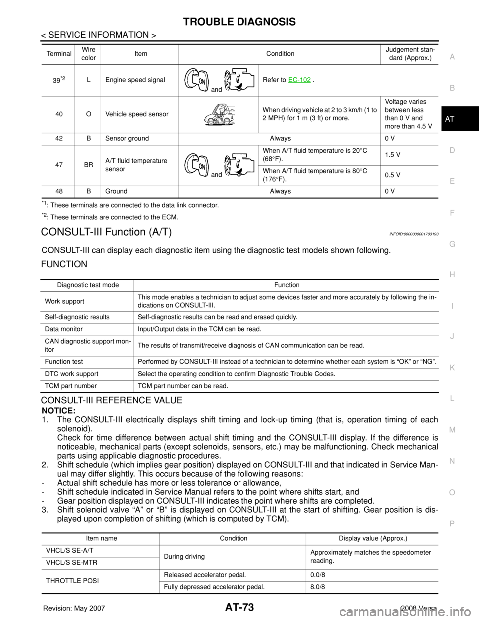
*1: These terminals are connected to the data link connector.
*2: These terminals are connected to the ECM.
CONSULT-III Function (A/T)INFOID:0000000001703193
CONSULT-III can display each diagnostic item using the diagnostic test models shown following.
FUNCTION
CONSULT-III REFERENCE VALUE
NOTICE:
1. The CONSULT-III electrically displays shift timing and lock-up timing (that is, operation timing of each
solenoid).
Check for time difference between actual shift timing and the CONSULT-III display. If the difference is
noticeable, mechanical parts (except solenoids, sensors, etc.) may be malfunctioning. Check mechanical
parts using applicable diagnostic procedures.
2. Shift schedule (which implies gear position) displayed on CONSULT-III and that indicated in Service Man-
ual may differ slightly. This occurs because of the following reasons:
- Actual shift schedule has more or less tolerance or allowance,
- Shift schedule indicated in Service Manual refers to the point where shifts start, and
- Gear position displayed on CONSULT-III indicates the point where shifts are completed.
3. Shift solenoid valve “A” or “B” is displayed on CONSULT-III at the start of shifting. Gear position is dis-
played upon completion of shifting (which is computed by TCM).
39*2L Engine speed signal
and Refer to EC-102 .
40 O Vehicle speed sensorWhen driving vehicle at 2 to 3 km/h (1 to
2 MPH) for 1 m (3 ft) or more.Voltage varies
between less
than 0 V and
more than 4.5 V
42 B Sensor ground Always 0 V
47 BRA/T fluid temperature
sensor
and When A/T fluid temperature is 20°C
(68°F).1.5 V
When A/T fluid temperature is 80°C
(176°F).0.5 V
48 B Ground Always 0 V Te r m i n a lWire
colorItem ConditionJudgement stan-
dard (Approx.)
Diagnostic test mode Function
Work supportThis mode enables a technician to adjust some devices faster and more accurately by following the in-
dications on CONSULT-III.
Self-diagnostic results Self-diagnostic results can be read and erased quickly.
Data monitor Input/Output data in the TCM can be read.
CAN diagnostic support mon-
itorThe results of transmit/receive diagnosis of CAN communication can be read.
Function test Performed by CONSULT-III instead of a technician to determine whether each system is “OK” or “NG”.
DTC work support Select the operating condition to confirm Diagnostic Trouble Codes.
TCM part number TCM part number can be read.
Item name Condition Display value (Approx.)
VHCL/S SE-A/T
During drivingApproximately matches the speedometer
reading.
VHCL/S SE-MTR
THROTTLE POSIReleased accelerator pedal. 0.0/8
Fully depressed accelerator pedal. 8.0/8
Page 170 of 2771
AT-158
< SERVICE INFORMATION >
DTC TURBINE REVOLUTION SENSOR
DTC TURBINE REVOLUTION SENSOR
DescriptionINFOID:0000000001703313
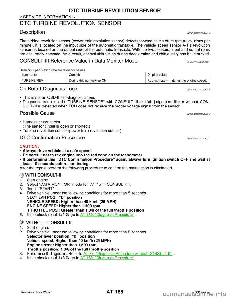
The turbine revolution sensor (power train revolution sensor) detects forward clutch drum rpm (revolutions per
minute). It is located on the input side of the automatic transaxle. The vehicle speed sensor A/T (Revolution
sensor) is located on the output side of the automatic transaxle. With the two sensors, input and output rpms
are accurately detected. As a result, optimal shift timing during deceleration and shift quality can be improved.
CONSULT-III Reference Value in Data Monitor ModeINFOID:0000000001703314
Remarks: Specification data are reference values.
On Board Diagnosis LogicINFOID:0000000001703315
• This is not an OBD-II self-diagnostic item.
• Diagnostic trouble code “TURBINE SENSOR” with CONSULT-III or 10th judgement flicker without CON-
SULT-III is detected when TCM does not receive the proper voltage signal from the sensor.
Possible CauseINFOID:0000000001703316
• Harness or connector
(The sensor circuit is open or shorted.)
• Turbine revolution sensor (power train revolution sensor)
DTC Confirmation ProcedureINFOID:0000000001703317
CAUTION:
• Always drive vehicle at a safe speed.
• Be careful not to rev engine into the red zone on the tachometer.
• If performing this “DTC Confirmation Procedure” again, always turn ignition switch OFF and wait at
least 10 seconds before continuing.
After the repair, perform the following procedure to confirm the malfunction is eliminated.
WITH CONSULT-III
1. Start engine.
2. Select “DATA MONITOR” mode for “A/T” with CONSULT-III.
3. Touch “START”.
4. Drive vehicle under the following conditions for more than 5 seconds.
SLCT LVR POSI: “D” position
VEHICLE SPEED: Higher than 40 km/h (25 MPH)
ENGINE SPEED: Higher than 1,500 rpm
THROTTLE POSI: Greater than 1.0/8 of the full throttle position
5. If the check result is NG, go to AT-160, "
Diagnosis Procedure" .
WITHOUT CONSULT-III
1. Start engine.
2. Drive vehicle under the following conditions for more than 5 seconds.
Selector lever position: “D” position
Vehicle speed: Higher than 40 km/h (25 MPH)
Engine speed: Higher than 1,500 rpm
Throttle position: 1.0/8 of the full throttle position
3. Perform self-diagnosis. Refer to AT-78, "
Diagnosis Procedure without CONSULT-III" .
4. If the check result is NG, go to AT-160, "
Diagnosis Procedure" .
Item name Condition Display value
TURBINE REV During driving (lock-up ON) Approximately matches the engine speed.
Page 782 of 2771
![NISSAN TIIDA 2008 Service Repair Manual TROUBLE DIAGNOSIS
BRC-17
< SERVICE INFORMATION >[ABS]
C
D
E
G
H
I
J
K
L
MA
B
BRC
N
O
P
• If ABS actuator and electric unit (control unit) connection is loose, tighten the piping to the specified
tor](/manual-img/5/57399/w960_57399-781.png "NISSAN TIIDA 2008 Service Repair Manual TROUBLE DIAGNOSIS
BRC-17
< SERVICE INFORMATION >[ABS]
C
D
E
G
H
I
J
K
L
MA
B
BRC
N
O
P
• If ABS actuator and electric unit (control unit) connection is loose, tighten the piping to the specified
tor")
TROUBLE DIAGNOSIS
BRC-17
< SERVICE INFORMATION >[ABS]
C
D
E
G
H
I
J
K
L
MA
B
BRC
N
O
P
• If ABS actuator and electric unit (control unit) connection is loose, tighten the piping to the specified
torque and recheck for leaks.
• If there is damage to the connection flare nut or ABS actuator and electric unit (control unit) threads,
replace the damaged part and recheck for leaks.
• When there is fluid leaking or seeping from a fluid connection, use a clean cloth to wipe off the fluid and
recheck for leaks. If fluid is still seeping out, replace the damaged part. If the fluid is leaking at the ABS
actuator and electric unit (control unit), replace the ABS actuator and electric unit (control unit) assem-
bly.
CAUTION:
The ABS actuator and electric unit (control unit) cannot be disassembled and must be replaced
as an assembly.
3. Check the brake pads for excessive wear.
POWER SYSTEM TERMINAL LOOSENESS AND BATTERY INSPECTION
Make sure the battery positive cable, negative cable and ground connection are not loose. In addition, make
sure the battery is sufficiently charged.
ABS WARNING LAMP INSPECTION
1. Make sure ABS warning lamp turns on for approximately 2 seconds when the ignition switch is turned ON.
If it does not, check CAN communications. If there are no errors with the CAN communication system,
replace the combination meter. Refer to IP-11, "
Removal and Installation".
2. Make sure the lamp turns off approximately 2 seconds after the ignition switch is turned ON. If the lamp
does not turn off, conduct self-diagnosis of ABS actuator and electric unit (control unit). If no malfunctions
are detected in self-diagnosis, replace combination meter. Refer to IP-11, "
Removal and Installation".
3. After conducting the self-diagnosis, be sure to erase the error memory. Refer to BRC-18, "
CONSULT-III
Function (ABS)".
Warning Lamp and Indicator TimingINFOID:0000000001703836
Note 1: Brake warning lamp will turn on when the parking brake is applied or when the brake fluid level is low.
x: ON
–: OFF
Control Unit Input/Output Signal StandardINFOID:0000000001703837
REFERENCE VALUE FROM CONSULT-III
CAUTION:
The display shows the control unit calculation data, so a normal value might be displayed even in the
event the output circuit (harness) is open or short circuited.
ConditionABS
warning lampBRAKE
warning lamp
[Note 1]Remarks
When the ignition switch is OFF – – –
After the ignition switch is turned ON for approx. 1
second××–
After the ignition switch is turned ON for approx. 2
seconds––Lamp goes off approx. 2 seconds after the
engine is started.
ABS malfunction×––
EBD malfunction××–
Page 783 of 2771
![NISSAN TIIDA 2008 Service Repair Manual BRC-18
< SERVICE INFORMATION >[ABS]
TROUBLE DIAGNOSIS
Note 1: Confirm tire pressure is normal.
Note 2: ON/OFF timing of ABS warning lamp
ON: For approximately 2 seconds after ignition switch is turned](/manual-img/5/57399/w960_57399-782.png "NISSAN TIIDA 2008 Service Repair Manual BRC-18
< SERVICE INFORMATION >[ABS]
TROUBLE DIAGNOSIS
Note 1: Confirm tire pressure is normal.
Note 2: ON/OFF timing of ABS warning lamp
ON: For approximately 2 seconds after ignition switch is turned")
BRC-18
< SERVICE INFORMATION >[ABS]
TROUBLE DIAGNOSIS
Note 1: Confirm tire pressure is normal.
Note 2: ON/OFF timing of ABS warning lamp
ON: For approximately 2 seconds after ignition switch is turned ON, or when a malfunction is detected.
OFF: Approximately 2 seconds after ignition switch is turned ON (when system is in normal operation).
CONSULT-III Function (ABS)INFOID:0000000001703838
CONSULT-III can display each diagnostic item using the diagnostic test modes shown following.
Monitor item Display contentData monitor
Note: Error inspection
checklist
ConditionReference value in
normal operation
FR RH SENSOR
FR LH SENSOR
RR RH SENSOR
RR LH SENSORWheel speedVehicle stopped 0 [km/h (MPH)]
BRC-24, "
Wheel Sensor
System"Vehicle running (Note 1)Almost in accor-
dance with speed-
ometer display
(within ±10%)
BATTERY VOLTBattery voltage sup-
plied to ABS actuator
and electric unit (con-
trol unit)Ignition switch ON 10 to 16VBRC-27, "
ABS Control
Unit Power and Ground
Systems Inspection"
STOP LAMP SWStop lamp switch oper-
ationBrake pedal depressed ON
—
Brake pedal not depressed OFF
ABS WARN LAMPABS warning lamp ON
condition (Note 2)ABS warning lamp ON ON
BRC-16, "
Basic Inspec-
tion"ABS warning lamp OFF OFF
MOTOR RELAYOperation status of mo-
tor and motor relayIgnition switch ON or running
(ABS not activated)OFF
BRC-26, "
Actuator Motor,
Motor Relay, and Circuit
Inspection"Ignition switch ON or engine
running (ABS activated)ON
ACTUATOR RLYActuator relay opera-
tion statusVehicle stopped (Ignition
switch ON)OFF
BRC-26, "
Actuator Motor,
Motor Relay, and Circuit
Inspection"Vehicle stopped (Engine run-
ning)ON
FR LH IN SOL
FR LH OUT SOL
FR RH IN SOL
FR RH OUT SOL
RR RH IN SOL
RR RH OUT SOL
RR LH IN SOL
RR LH OUT SOLSolenoid valve opera-
tionActuator (solenoid) is active
(“ACTIVE TEST” with CON-
SULT-III) or actuator relay is in-
active (in fail-safe mode).ON
BRC-25, "
Solenoid Valve
System Inspection"When actuator (solenoid) is not
active and actuator relay is ac-
tive (ignition switch ON).OFF
ABS SIGNAL
EBD SIGNALSignal statusABS active
EBD activeON
ABS system
EBD system
ABS not active
EBD not activeOFF
ABS FAIL SIG
EBD FAIL SIGFail signal statusABS fail
EBD failON
ABS system
EBD system
ABS normal
EBD normalOFF
ABS diagnostic mode Description
SELF-DIAG RESULTS Displays ABS actuator and electric unit (control unit) self-diagnosis results.
DATA MONITOR Displays ABS actuator and electric unit (control unit) input/output data in real time.
CAN DIAG SUPPORT MNTR The result of transmit/receive diagnosis of CAN communication can be read.
ACTIVE TEST Operation of electrical loads can be checked by sending drive signal to them.
Page 823 of 2771

CO-6
< SERVICE INFORMATION >
OVERHEATING CAUSE ANALYSIS
Except cool-
ing system
parts mal-
function— Overload on engineAbusive drivingHigh engine rpm under no
load
Driving in low gear for ex-
tended time
Driving at extremely high
speed
Power train system mal-
function
— Installed improper size
wheels and tires
Dragging brakes
Improper ignition timing
Blocked or restricted air
flowBlocked bumper —
Installed front bumper fas-
cia cover
— Blocked radiator grille
Mud contamination or paper
clogging
Blocked radiator
—
Blocked air flow Blocked condenser
Installed large fog lamp Symptom Check items
Page 993 of 2771
CVT-154
< SERVICE INFORMATION >
TROUBLE DIAGNOSIS FOR SYMPTOMS
OK or NG
OK >>INSPECTION END
NG >> Replace the transaxle assembly. Refer to CVT-178, "
Removal and Installation".
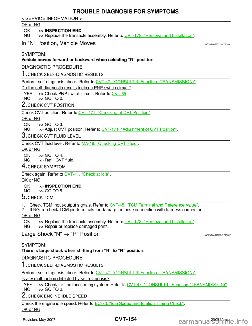
In "N" Position, Vehicle MovesINFOID:0000000001703666
SYMPTOM:
Vehicle moves forward or backward when selecting “N” position.
DIAGNOSTIC PROCEDURE
1.CHECK SELF-DIAGNOSTIC RESULTS
Perform self-diagnosis check. Refer to CVT-47, "
CONSULT-III Function (TRANSMISSION)".
Do the self-diagnostic results indicate PNP switch circuit?
YES >> Check PNP switch circuit. Refer to CVT-65.
NO >> GO TO 2.
2.CHECK CVT POSITION
Check CVT position. Refer to CVT-171, "
Checking of CVT Position"
OK or NG
OK >> GO TO 3.
NG >> Adjust CVT position. Refer to CVT-171, "
Adjustment of CVT Position".
3.CHECK CVT FLUID LEVEL
Check CVT fluid level. Refer to MA-19, "
Checking CVT Fluid".
OK or NG
OK >> GO TO 4.
NG >> Refill CVT fluid.
4.CHECK SYMPTOM
Check again. Refer to CVT-41, "
Check at Idle".
OK or NG
OK >>INSPECTION END
NG >> GO TO 5.
5.CHECK TCM
1. Check TCM input/output signals. Refer to CVT-45, "
TCM Terminal and Reference Value".
2. If NG, re-check TCM pin terminals for damage or loose connection with harness connector.
OK or NG
OK >> Replace the transaxle assembly. Refer to CVT-178, "Removal and Installation".
NG >> Repair or replace damaged parts.
Large Shock "N" → "R" PositionINFOID:0000000001703667
SYMPTOM:
There is large shock when shifting from “N” to “R” position.
DIAGNOSTIC PROCEDURE
1.CHECK SELF-DIAGNOSTIC RESULTS
Perform self-diagnosis check. Refer to CVT-47, "
CONSULT-III Function (TRANSMISSION)".
Is any malfunction detected by self-diagnosis?
YES >> Check the malfunctioning system. Refer to CVT-47, "CONSULT-III Function (TRANSMISSION)".
NO >> GO TO 2.
2.CHECK ENGINE IDLE SPEED
Check the engine idle speed. Refer to EC-73, "
Idle Speed and Ignition Timing Check".
OK or NG