2008 NISSAN TIIDA tools
[x] Cancel search: toolsPage 2 of 2771
-2
This manual contains maintenance and repair procedures for the
2008 NISSAN VERSA.
In order to assure your safety and the efficient functioning of the vehicle,
this manual should be read thoroughly. It is especially important that the
PRECAUTIONS in the GI section be completely understood before starting
any repair task.
All information in this manual is based on the latest product information
at the time of publication. The right is reserved to make changes in specifi-
cations and methods at any time without notice.
IMPORTANT SAFETY NOTICE
The proper performance of service is essential for both the safety of
the technician and the efficient functioning of the vehicle.
The service methods in this Service Manual are described in such a
manner that the service may be performed safely and accurately.
Service varies with the procedures used, the skills of the technician
and the tools and parts available. Accordingly, anyone using service
procedures, tools or parts which are not specifically recommended
by NISSAN must first be completely satisfied that neither personal
safety nor the vehicle’s safety will be jeopardized by the service
method selected.
Page 5 of 2771
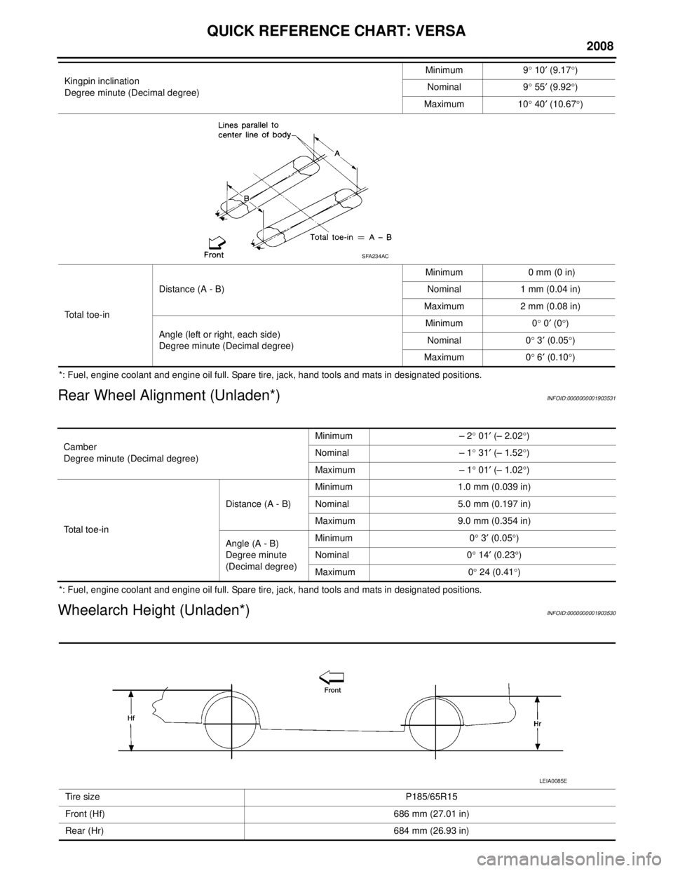
QUICK REFERENCE CHART: VERSA
2008
*: Fuel, engine coolant and engine oil full. Spare tire, jack, hand tools and mats in designated positions.
Rear Wheel Alignment (Unladen*)INFOID:0000000001903531
*: Fuel, engine coolant and engine oil full. Spare tire, jack, hand tools and mats in designated positions.
Wheelarch Height (Unladen*)INFOID:0000000001903530
Kingpin inclination
Degree minute (Decimal degree)Minimum 9
° 10 ′ (9.17 °)
Nominal 9 ° 55 ′ (9.92 °)
Maximum 10 ° 40 ′ (10.67 °)
Total toe-in Distance (A - B)
Minimum 0 mm (0 in)
Nominal 1 mm (0.04 in)
Maximum 2 mm (0.08 in)
Angle (left or right, each side)
Degree minute (Decimal degree) Minimum 0
° 0 ′ (0 °)
Nominal 0 ° 3 ′ (0.05 °)
Maximum 0 ° 6 ′ (0.10 °)
SFA234AC
Camber
Degree minute (Decimal degree) Minimum – 2
° 01 ′ (– 2.02 °)
Nominal – 1 ° 31 ′ (– 1.52 °)
Maximum – 1 ° 01 ′ (– 1.02 °)
Total toe-in Distance (A - B)
Minimum 1.0 mm (0.039 in)
Nominal 5.0 mm (0.197 in)
Maximum 9.0 mm (0.354 in)
Angle (A - B)
Degree minute
(Decimal degree) Minimum 0
° 3 ′ (0.05 °)
Nominal 0 ° 14 ′ (0.23 °)
Maximum 0 ° 24 (0.41 °)
Tire size P185/65R15
Front (Hf) 686 mm (27.01 in)
Rear (Hr) 684 mm (26.93 in)
LEIA0085E
Page 6 of 2771

2008
QUICK REFERENCE CHART: VERSA
*: Fuel, engine coolant and engine oil full. Spare tire, jack, hand tools and mats in designated positions.
General SpecificationINFOID:0000000001903532
Brake PedalINFOID:0000000001903533
Unit: mm (in)
Front Disc BrakeINFOID:0000000001903534
Unit: mm (in)
Rear Drum BrakeINFOID:0000000001903535
Unit: mm (in)
Front brake Brake model CLZ25VACylinder bore diameter 57.2 mm (2.252 in)
Pad
Length × width × thickness 125.6 mm
× 46.0 mm × 9.5 mm
(4.945 in × 1.811 in × 0.374 in)
Rotor outer diameter × thickness 280 mm × 24.0 mm (11.02 in × 0.945 in)
Rear brake Brake model LT20D Cylinder bore diameter 15.87 mm (0.625 in)
Lining
Length × width × thickness 194.1 mm
× 30.0 mm × 4.0 mm
(7.642 in × 1.181 in × 0.157 in)
Drum outer diameter 228.6 mm (9.000 in)
Master cylinder Cylinder bore diameter 22.22 mm (0.875 in)
Control valve Valve model Electric brake force distribution
Brake booster Booster model C255 Diaphragm diameter 255 mm (10.04 in)
Brake pedal free height (from dash panel top surface) A/T, CVT model 172.4 - 182.4 (6.79 - 7.18)
M/T model 162.3 - 172.3 (6.39 - 6.78)
Brake pedal depressed height
[under a force of 490 N (50 kg-f, 110 lb-f) with the engine running] A/T, CVT model 98 (3.86) or more
M/T model 90 (3.54) or more
Clearance between brake pedal lever and the threaded end of stop lamp switch 0.74 - 1.96 (0.0291 - 0.0772)
Pedal play 3 - 11 (0.12 - 0.43)
Brake modelCLZ25VA
Brake pad Standard thickness (new) 9.5 (0.374)
Repair limit thickness 2.0 (0.079)
Disc rotor Standard thickness (new) 24.0 (0.945)
Repair limit thickness 22.0 (0.866)
Runout limit 0.04 (0.0016)
Maximum uneven wear (mea-
sured at 8 positions)
0.02 mm (0.0008 in) or less
Brake model
LT 2 0 D
Brake lining Standard thickness (new) 4.0 (0.157)
Repair limit thickness 1.5 (0.059)
Drum Standard inner diameter (new) 228.6 (9.000)
Repair limit inner diameter 230.0 (9.055)
Page 22 of 2771
AT-10
< SERVICE INFORMATION >
PREPARATION
PREPARATION
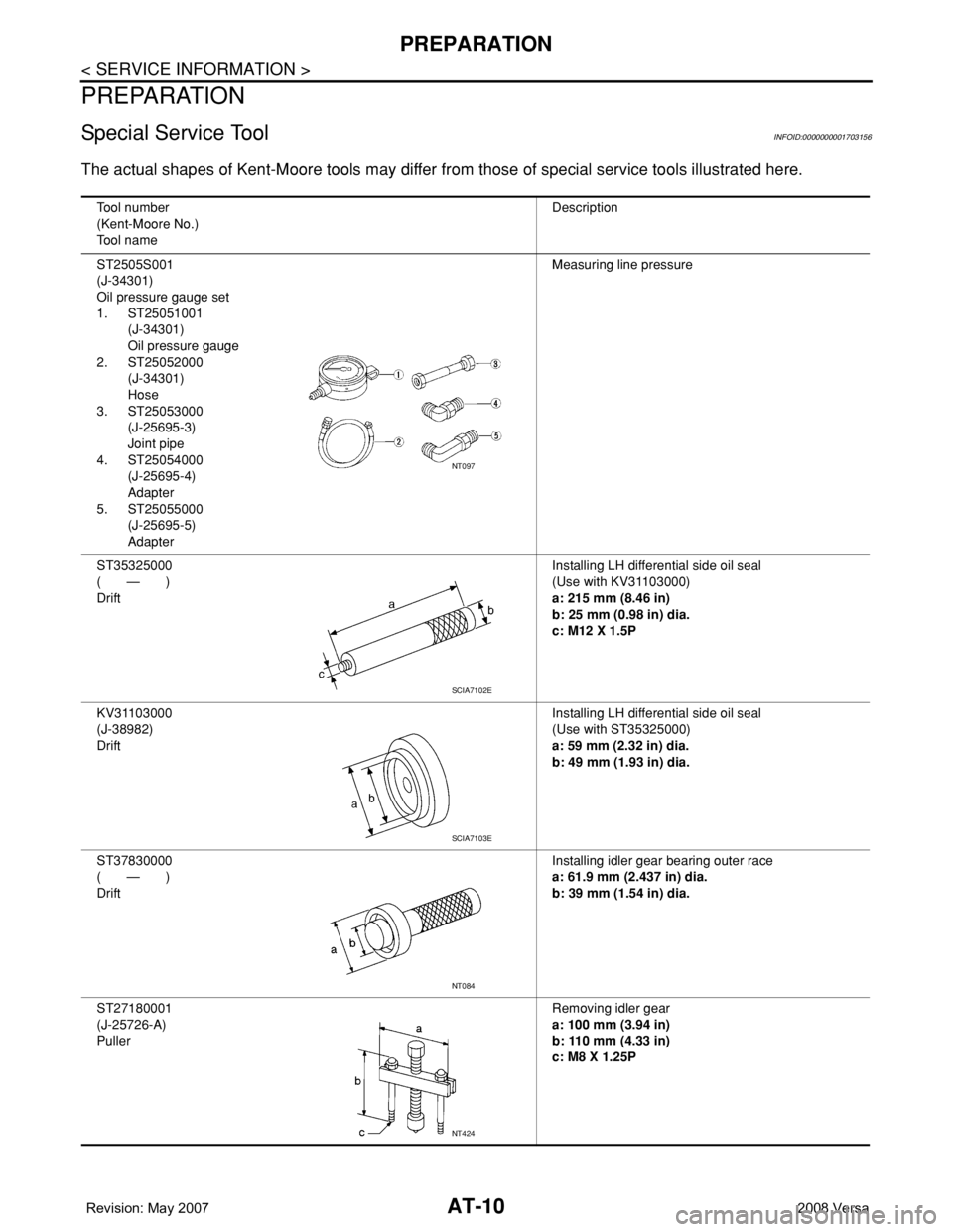
Special Service ToolINFOID:0000000001703156
The actual shapes of Kent-Moore tools may differ from those of special service tools illustrated here.
Tool number
(Kent-Moore No.)
Tool nameDescription
ST2505S001
(J-34301)
Oil pressure gauge set
1. ST25051001
(J-34301)
Oil pressure gauge
2. ST25052000
(J-34301)
Hose
3. ST25053000
(J-25695-3)
Joint pipe
4. ST25054000
(J-25695-4)
Adapter
5. ST25055000
(J-25695-5)
AdapterMeasuring line pressure
ST35325000
( — )
DriftInstalling LH differential side oil seal
(Use with KV31103000)
a: 215 mm (8.46 in)
b: 25 mm (0.98 in) dia.
c: M12 X 1.5P
KV31103000
(J-38982)
DriftInstalling LH differential side oil seal
(Use with ST35325000)
a: 59 mm (2.32 in) dia.
b: 49 mm (1.93 in) dia.
ST37830000
( — )
DriftInstalling idler gear bearing outer race
a: 61.9 mm (2.437 in) dia.
b: 39 mm (1.54 in) dia.
ST27180001
(J-25726-A)
PullerRemoving idler gear
a: 100 mm (3.94 in)
b: 110 mm (4.33 in)
c: M8 X 1.25P
NT097
SCIA7102E
SCIA7103E
NT084
NT424
Page 49 of 2771
ON BOARD DIAGNOSTIC (OBD) SYSTEM
AT-37
< SERVICE INFORMATION >
D
E
F
G
H
I
J
K
L
MA
B
AT
N
O
P
Data which are stored in the ECM memory, along with the 1st trip DTC, are called 1st trip freeze frame data,
and the data, stored together with the DTC data, are called freeze frame data and displayed on CONSULT-III
or GST. The 1st trip freeze frame data can only be displayed on the CONSULT-III screen, not on the GST. For
detail, refer to EC-109, "
CONSULT-II Function (ENGINE)" .
Only one set of freeze frame data (either 1st trip freeze frame data of freeze frame data) can be stored in the
ECM. 1st trip freeze frame data is stored in the ECM memory along with the 1st trip DTC. There is no priority
for 1st trip freeze frame data and it is updated each time a different 1st trip DTC is detected. However, once
freeze frame data (2nd trip detection/MIL on) is stored in the ECM memory, 1st trip freeze frame data is no
longer stored. Remember, only one set of freeze frame data can be stored in the ECM. The ECM has the fol-
lowing priorities to update the data.
Both 1st trip freeze frame data and freeze frame data (along with the DTC) are cleared when the ECM mem-
ory is erased.
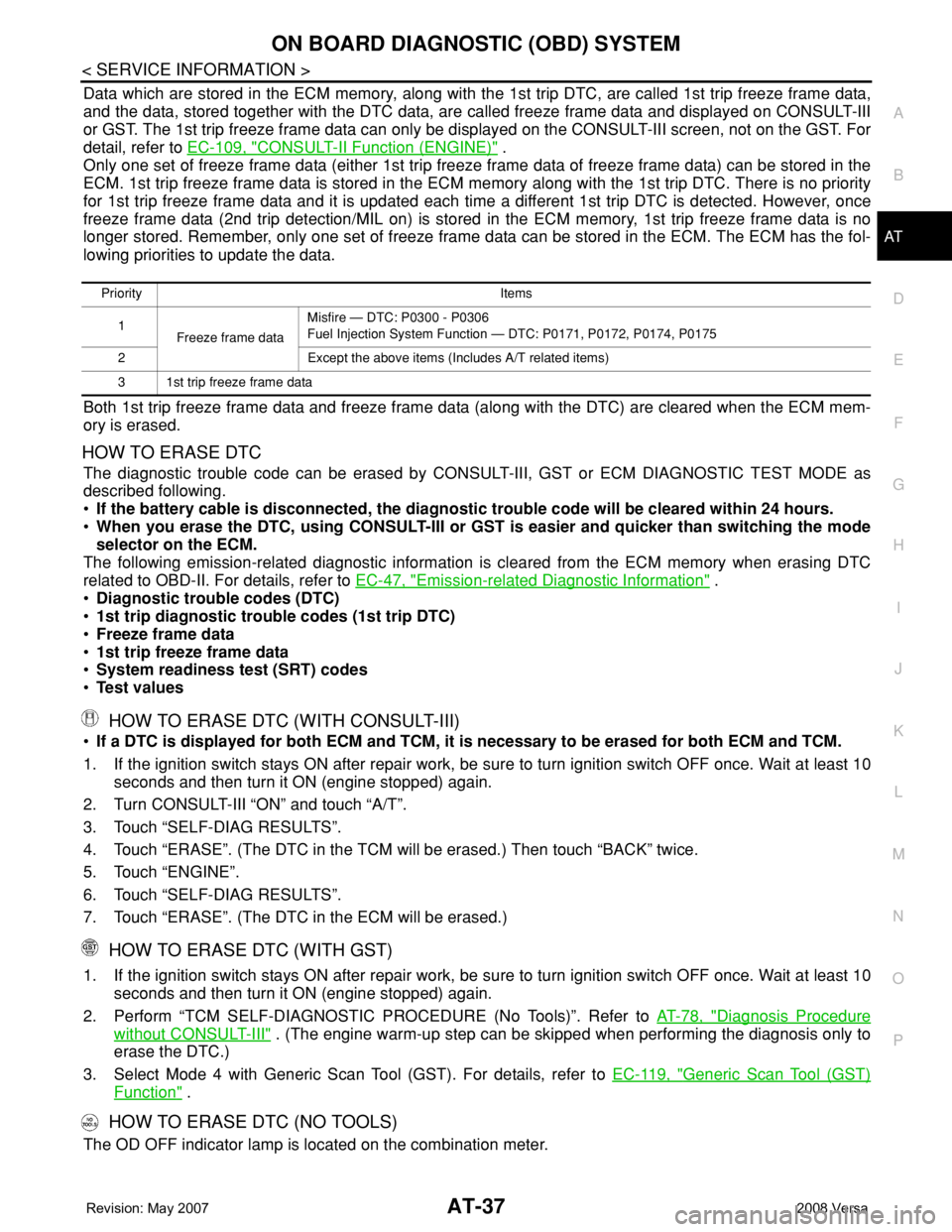
HOW TO ERASE DTC
The diagnostic trouble code can be erased by CONSULT-III, GST or ECM DIAGNOSTIC TEST MODE as
described following.
•If the battery cable is disconnected, the diagnostic trouble code will be cleared within 24 hours.
•When you erase the DTC, using CONSULT-III or GST is easier and quicker than switching the mode
selector on the ECM.
The following emission-related diagnostic information is cleared from the ECM memory when erasing DTC
related to OBD-II. For details, refer to EC-47, "
Emission-related Diagnostic Information" .
•Diagnostic trouble codes (DTC)
•1st trip diagnostic trouble codes (1st trip DTC)
•Freeze frame data
•1st trip freeze frame data
•System readiness test (SRT) codes
•Test values
HOW TO ERASE DTC (WITH CONSULT-III)
•If a DTC is displayed for both ECM and TCM, it is necessary to be erased for both ECM and TCM.
1. If the ignition switch stays ON after repair work, be sure to turn ignition switch OFF once. Wait at least 10
seconds and then turn it ON (engine stopped) again.
2. Turn CONSULT-III “ON” and touch “A/T”.
3. Touch “SELF-DIAG RESULTS”.
4. Touch “ERASE”. (The DTC in the TCM will be erased.) Then touch “BACK” twice.
5. Touch “ENGINE”.
6. Touch “SELF-DIAG RESULTS”.
7. Touch “ERASE”. (The DTC in the ECM will be erased.)
HOW TO ERASE DTC (WITH GST)
1. If the ignition switch stays ON after repair work, be sure to turn ignition switch OFF once. Wait at least 10
seconds and then turn it ON (engine stopped) again.
2. Perform “TCM SELF-DIAGNOSTIC PROCEDURE (No Tools)”. Refer to AT-78, "
Diagnosis Procedure
without CONSULT-III" . (The engine warm-up step can be skipped when performing the diagnosis only to
erase the DTC.)
3. Select Mode 4 with Generic Scan Tool (GST). For details, refer to EC-119, "
Generic Scan Tool (GST)
Function" .
HOW TO ERASE DTC (NO TOOLS)
The OD OFF indicator lamp is located on the combination meter.
Priority Items
1
Freeze frame dataMisfire — DTC: P0300 - P0306
Fuel Injection System Function — DTC: P0171, P0172, P0174, P0175
2 Except the above items (Includes A/T related items)
3 1st trip freeze frame data
Page 50 of 2771
AT-38
< SERVICE INFORMATION >
ON BOARD DIAGNOSTIC (OBD) SYSTEM
1. If the ignition switch stays ON after repair work, be sure to turn ignition switch OFF once. Wait at least 10
seconds and then turn it ON (engine stopped) again.
2. Perform “TCM SELF-DIAGNOSTIC PROCEDURE (No Tools)”. Refer to AT-78, "
Diagnosis Procedure
without CONSULT-III" . (The engine warm-up step can be skipped when performing the diagnosis only to
erase the DTC.)
3. Perform “OBD-II SELF-DIAGNOSTIC PROCEDURE (No tools)”. Refer to EC-47, "
Emission-related Diag-
nostic Information" .
Malfunction Indicator Lamp (MIL)INFOID:0000000001703176
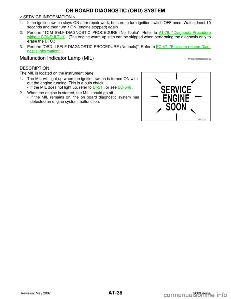
DESCRIPTION
The MIL is located on the instrument panel.
1. The MIL will light up when the ignition switch is turned ON with-
out the engine running. This is a bulb check.
• If the MIL does not light up, refer to DI-21
, or see EC-546 .
2. When the engine is started, the MIL should go off.
• If the MIL remains on, the on board diagnostic system has
detected an engine system malfunction.
SEF217U
Page 706 of 2771

BL-272
< SERVICE INFORMATION >
BODY REPAIR
This section is prepared for technicians who have attained a high level of skill and experience in repairing col-
lision-damaged vehicles and also use modern service tools and equipment. Persons unfamiliar with body
repair techniques should not attempt to repair collision-damaged vehicles by using this section.
Technicians are also encouraged to read Body Repair Manual (Fundamentals) in order to ensure that the orig-
inal functions and quality of the vehicle can be maintained. The Body Repair Manual (Fundamentals) contains
additional information, including cautions and warnings, that are not including in this manual. Technicians
should refer to both manuals to ensure proper repairs.
Please note that this information is prepared for worldwide usage, and as such, certain procedures may not
apply in some regions or countries.
Page 769 of 2771
![NISSAN TIIDA 2008 Service Repair Manual BRC-4
< SERVICE INFORMATION >[ABS]
PREPARATION
PREPARATION
Special Service ToolINFOID:0000000001703823
The actual shapes of Kent-Moore tools may differ from those of special service tools illustrated NISSAN TIIDA 2008 Service Repair Manual BRC-4
< SERVICE INFORMATION >[ABS]
PREPARATION
PREPARATION
Special Service ToolINFOID:0000000001703823
The actual shapes of Kent-Moore tools may differ from those of special service tools illustrated](/manual-img/5/57399/w960_57399-768.png)
BRC-4
< SERVICE INFORMATION >[ABS]
PREPARATION
PREPARATION
Special Service ToolINFOID:0000000001703823
The actual shapes of Kent-Moore tools may differ from those of special service tools illustrated here.
Commercial Service ToolINFOID:0000000001703824
Tool number
(Kent-Moore No.)
Tool nameDescription
KV991J0080
(J-45741)
ABS active wheel sensor testerChecking operation of ABS active wheel sen-
sors
WFIA0101E
Tool nameDescription
1. Flare nut crowfoot
2. Torque wrenchRemoving and installing brake piping
a: 10 mm (0.39 in)/12 mm (0.47 in)
S-NT360