2008 NISSAN TIIDA tire type
[x] Cancel search: tire typePage 768 of 2771
![NISSAN TIIDA 2008 Service Repair Manual PRECAUTIONS
BRC-3
< SERVICE INFORMATION >[ABS]
C
D
E
G
H
I
J
K
L
MA
B
BRC
N
O
P
• When an error is indicated by ABS or another warning lamp, collect all necessary information from customer
(what sym NISSAN TIIDA 2008 Service Repair Manual PRECAUTIONS
BRC-3
< SERVICE INFORMATION >[ABS]
C
D
E
G
H
I
J
K
L
MA
B
BRC
N
O
P
• When an error is indicated by ABS or another warning lamp, collect all necessary information from customer
(what sym](/manual-img/5/57399/w960_57399-767.png)
PRECAUTIONS
BRC-3
< SERVICE INFORMATION >[ABS]
C
D
E
G
H
I
J
K
L
MA
B
BRC
N
O
P
• When an error is indicated by ABS or another warning lamp, collect all necessary information from customer
(what symptoms are present under what conditions) and check for simple causes before starting diagnosis.
Besides electrical system inspection, check brake booster operation, brake fluid level, and fluid leaks.
• If incorrect tire sizes or types are installed on the vehicle or brake pads are not Genuine NISSAN parts, stop-
ping distance or steering stability may deteriorate.
• If there is a radio, antenna or related wiring near the control module, ABS function may have a malfunction
or error.
• If aftermarket parts (car stereo, CD player, etc.) have been installed, check for incidents such as harness
pinches, open circuits or improper wiring.
Precaution for CAN SystemINFOID:0000000001703822
• Do not apply voltage of 7.0V or higher to terminal to be measured.
• Maximum open terminal voltage of tester in use must be less than 7.0V.
• Before checking harnesses, turn ignition switch OFF and disconnect battery negative cable.
• Area to be repaired must be soldered and wrapped with tape.
Make sure that fraying of twisted wire is within 110 mm (4.33 in).
• Do not make a bypass connection to repaired area. (If the circuit is
bypassed, characteristics of twisted wire will be lost.)
PKIA0306E
PKIA0307E
Page 1781 of 2771

EM-104
< SERVICE INFORMATION >
SERVICE DATA AND SPECIFICATIONS (SDS)
SERVICE DATA AND SPECIFICATIONS (SDS)
Standard and LimitINFOID:0000000001702513
GENERAL SPECIFICATIONS
DRIVE BELT
WATER CONTROL VALVE
EXHAUST MANIFOLD
Unit: mm (in)
THERMOSTAT
SPARK PLUG
Unit: mm (in)
CYLINDER HEAD
Engine typeMR18DE
Cylinder arrangementIn-line 4
Displacement
cm
3 (cu in)1,797 (109.65)
Bore and stroke mm (in) 84.0 x 81.1 (3.307 x 3.192)
Valve arrangementDOHC
Firing order1-3-4-2
Number of piston ringsCompression 2
Oil 1
Compression ratio9.9
Compression pressure
kPa (bar, kg/cm
2 , psi) / 250 rpmStandard 1,500 (15.0, 15.3, 217.6)
Minimum 1,200 (12.0, 12.2, 174)
Differential limit between cylinders 100 (1.0, 1.0, 15)
Tension of drive belt Auto adjustment by auto-tensioner
Valve opening temperature 93.5 - 96.5°C (200 - 206°F)
Maximum valve lift 8 mm/ 108°C (0.315 in/ 226°F)
Valve closing temperature More than 90°C (194°F)
Items Limit
Surface distortionEach exhaust port 0.3 (0.012)
Entire part 0.7 (0.028)
Valve opening temperature 80.5 - 83.5°C (177 - 182°F)
Maximum valve lift 8 mm/ 95°C (0.315 in/ 203°F)
Valve closing temperature More than 77°C (171°F)
Plug typeIridium-tipped TYPE
MakeDENSO
Standard typeFXE20HR11
Spark plug gapNominal: 1.1 (0.043)
Page 1836 of 2771
FSU-2
< SERVICE INFORMATION >
PRECAUTIONS
SERVICE INFORMATION
PRECAUTIONS
Precaution for Supplemental Restraint System (SRS) "AIR BAG" and "SEAT BELT
PRE-TENSIONER"
INFOID:0000000001703715
The Supplemental Restraint System such as “AIR BAG” and “SEAT BELT PRE-TENSIONER”, used along
with a front seat belt, helps to reduce the risk or severity of injury to the driver and front passenger for certain
types of collision. This system includes seat belt switch inputs and dual stage front air bag modules. The SRS
system uses the seat belt switches to determine the front air bag deployment, and may only deploy one front
air bag, depending on the severity of a collision and whether the front occupants are belted or unbelted.
Information necessary to service the system safely is included in the SRS and SB section of this Service Man-
ual.
WARNING:
• To avoid rendering the SRS inoperative, which could increase the risk of personal injury or death in
the event of a collision which would result in air bag inflation, all maintenance must be performed by
an authorized NISSAN/INFINITI dealer.
• Improper maintenance, including incorrect removal and installation of the SRS, can lead to personal
injury caused by unintentional activation of the system. For removal of Spiral Cable and Air Bag
Module, see the SRS section.
• Do not use electrical test equipment on any circuit related to the SRS unless instructed to in this
Service Manual. SRS wiring harnesses can be identified by yellow and/or orange harnesses or har-
ness connectors.
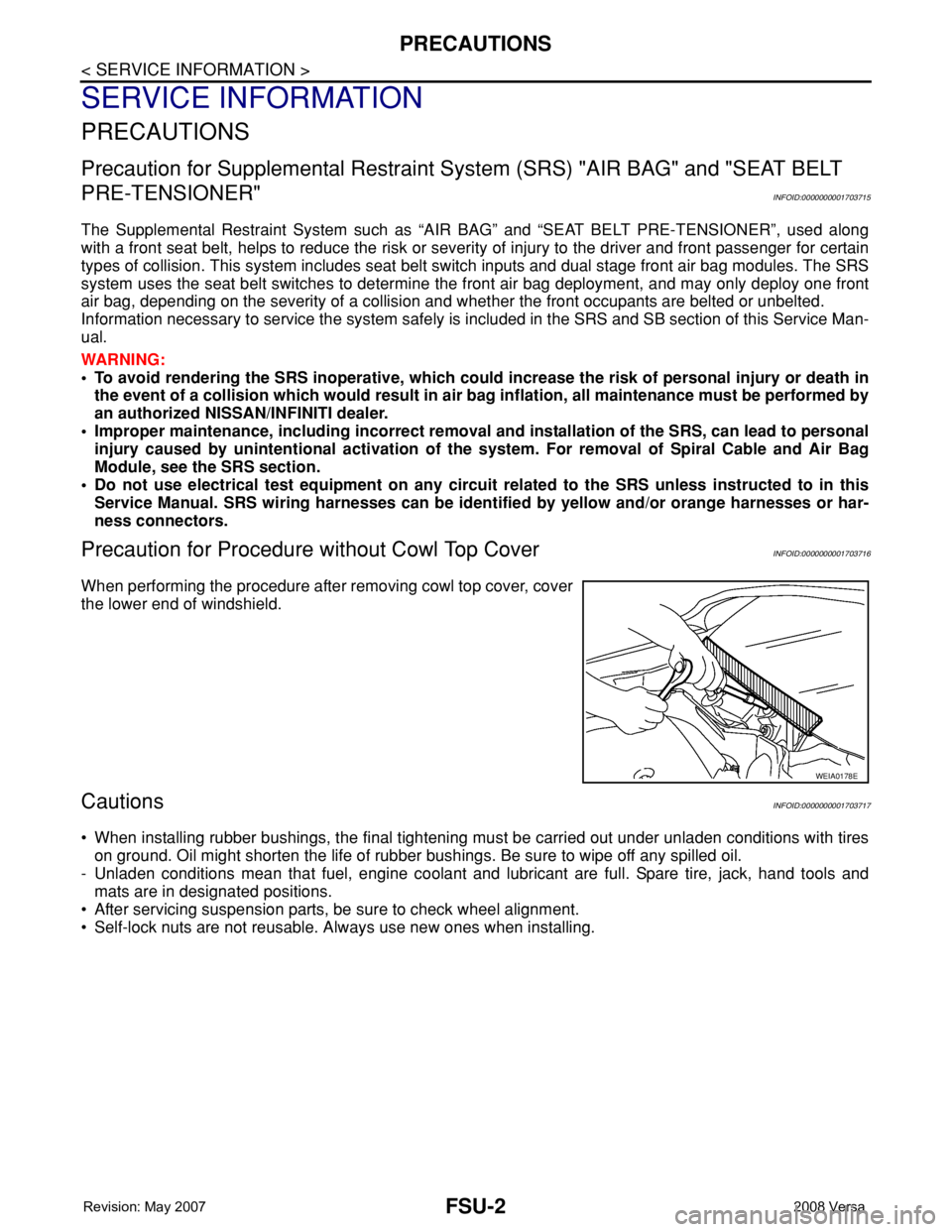
Precaution for Procedure without Cowl Top CoverINFOID:0000000001703716
When performing the procedure after removing cowl top cover, cover
the lower end of windshield.
CautionsINFOID:0000000001703717
• When installing rubber bushings, the final tightening must be carried out under unladen conditions with tires
on ground. Oil might shorten the life of rubber bushings. Be sure to wipe off any spilled oil.
- Unladen conditions mean that fuel, engine coolant and lubricant are full. Spare tire, jack, hand tools and
mats are in designated positions.
• After servicing suspension parts, be sure to check wheel alignment.
• Self-lock nuts are not reusable. Always use new ones when installing.
WEIA0178E
Page 1840 of 2771
FSU-6
< SERVICE INFORMATION >
FRONT SUSPENSION ASSEMBLY
FRONT SUSPENSION ASSEMBLY
On-Vehicle Inspection and ServiceINFOID:0000000001703721
Make sure the mounting conditions (looseness, back lash) of each component and component conditions
(wear, damage) are normal.
INSPECTION OF LOWER BALL JOINT END PLAY
1. Set front wheels in a straight-ahead position. Do not depress brake pedal.
2. Place an iron bar or similar tool between transverse link and steering knuckle.
3. Measure axial end play by prying it up and down.
CAUTION:
Be careful not to damage ball joint boot. Do not damage the installation position by applying
excessive force.
STRUT INSPECTION
Check for oil leakage, damage and replace as necessary.
Wheel Alignment InspectionINFOID:0000000001703722
PRELIMINARY INSPECTION
WARNING:
Always adjust the alignment with the vehicle on a flat surface.
NOTE:
If alignment is out of specification, inspect and replace any damaged or worn rear suspension parts before
making any adjustments.
1. Check and adjust the wheel alignment with the vehicle under unladen conditions. “Unladen conditions”
means that the fuel, coolant, and lubricant are full; and that the spare tire, jack, hand tools and mats are in
their designated positions.
2. Check the tires for incorrect air pressure and excessive wear.
3. Check the wheels for run out and damage. Refer to WT-5, "
Inspection" .
4. Check the wheel bearing axial end play. Refer to FA X - 5 , "
On-Vehicle Inspection and Service" .
5. Check the shock absorbers for leaks or damage.
6. Check each mounting point of the suspension components for any excessive looseness or damage.
7. Check each link, arm, and the suspension member for any damage.
8. Check the vehicle height. Refer to FSU-17, "
Wheelarch Height (Unladen*)" .
GENERAL INFORMATION AND RECOMMENDATIONS
1. A Four-Wheel Thrust Alignment should be performed.
• This type of alignment is recommended for any NISSAN vehicle.
• The four-wheel “thrust” process helps ensure that the vehicle is properly aligned and the steering wheel
is centered.
• The alignment machine itself should be capable of accepting any NISSAN vehicle.
• The alignment machine should be checked to ensure that it is level.
2. Make sure the alignment machine is properly calibrated.
• Your alignment machine should be regularly calibrated in order to give correct information.
• Check with the manufacturer of your specific alignment machine for their recommended Service/Cali-
bration Schedule.
THE ALIGNMENT PROCESS
IMPORTANT: Use only the alignment specifications listed in this Service Manual. Refer to FSU-16, "Wheel
Alignment (Unladen*)" .
1. When displaying the alignment settings, many alignment machines use “indicators”: (Green/red, plus or
minus, Go/No Go). Do NOT use these indicators.
• The alignment specifications programmed into your alignment machine that operate these indicators
may not be correct.Axial end play : 0 mm (0 in)
Page 1895 of 2771
GI-44
< SERVICE INFORMATION >
IDENTIFICATION INFORMATION
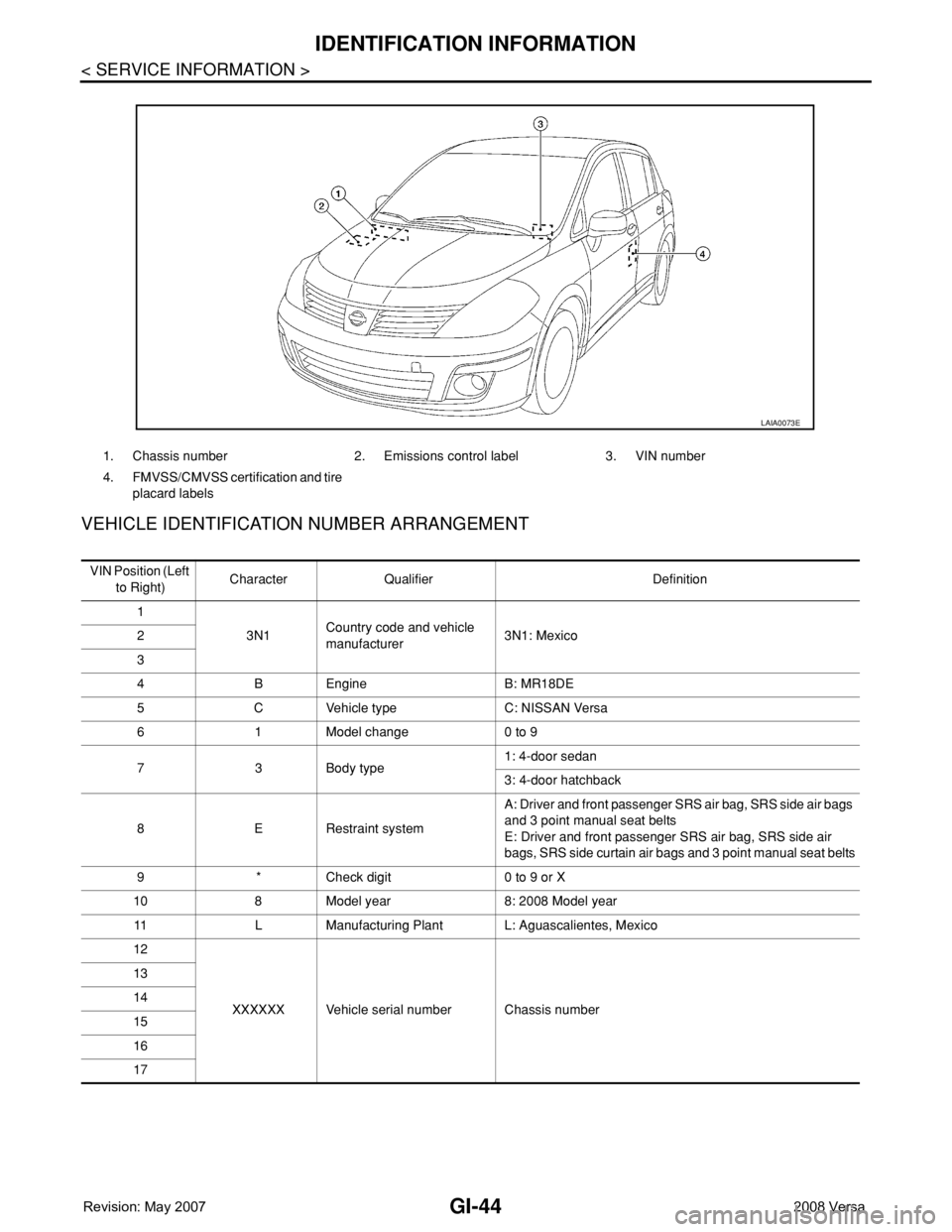
VEHICLE IDENTIFICATION NUMBER ARRANGEMENT
1. Chassis number 2. Emissions control label 3. VIN number
4. FMVSS/CMVSS certification and tire
placard labels
LAIA0073E
VIN Position (Left
to Right)Character Qualifier Definition
1
3N1Country code and vehicle
manufacturer3N1: Mexico 2
3
4 B Engine B: MR18DE
5 C Vehicle type C: NISSAN Versa
6 1 Model change 0 to 9
7 3 Body type1: 4-door sedan
3: 4-door hatchback
8 E Restraint systemA: Driver and front passenger SRS air bag, SRS side air bags
and 3 point manual seat belts
E: Driver and front passenger SRS air bag, SRS side air
bags, SRS side curtain air bags and 3 point manual seat belts
9 * Check digit 0 to 9 or X
10 8 Model year 8: 2008 Model year
11 L Manufacturing Plant L: Aguascalientes, Mexico
12
XXXXXX Vehicle serial number Chassis number 13
14
15
16
17
Page 2183 of 2771
LT-46
< SERVICE INFORMATION >
FRONT FOG LAMP
1. Check continuity between front fog lamp harness connector and
ground.
OK or NG
OK >> Replace IPDM E/R. Refer to PG-26, "Removal and
Installation of IPDM E/R" .
NG >> Repair harness or connector.
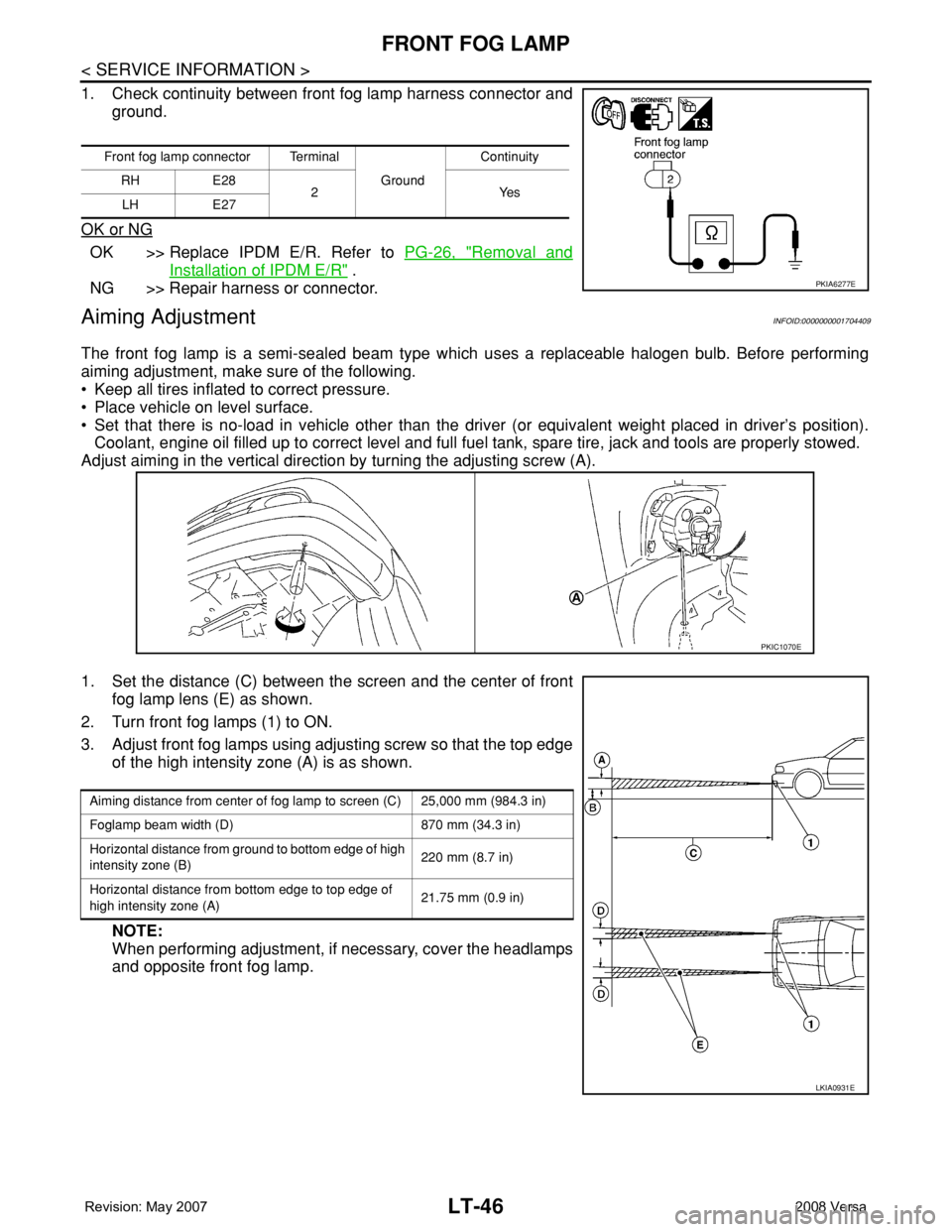
Aiming AdjustmentINFOID:0000000001704409
The front fog lamp is a semi-sealed beam type which uses a replaceable halogen bulb. Before performing
aiming adjustment, make sure of the following.
• Keep all tires inflated to correct pressure.
• Place vehicle on level surface.
• Set that there is no-load in vehicle other than the driver (or equivalent weight placed in driver’s position).
Coolant, engine oil filled up to correct level and full fuel tank, spare tire, jack and tools are properly stowed.
Adjust aiming in the vertical direction by turning the adjusting screw (A).
1. Set the distance (C) between the screen and the center of front
fog lamp lens (E) as shown.
2. Turn front fog lamps (1) to ON.
3. Adjust front fog lamps using adjusting screw so that the top edge
of the high intensity zone (A) is as shown.
NOTE:
When performing adjustment, if necessary, cover the headlamps
and opposite front fog lamp.
Front fog lamp connector Terminal
Ground Continuity
RH E28
2Yes
LH E27
PKIA6277E
PKIC1070E
Aiming distance from center of fog lamp to screen (C) 25,000 mm (984.3 in)
Foglamp beam width (D) 870 mm (34.3 in)
Horizontal distance from ground to bottom edge of high
intensity zone (B)220 mm (8.7 in)
Horizontal distance from bottom edge to top edge of
high intensity zone (A)21.75 mm (0.9 in)
LKIA0931E
Page 2267 of 2771
![NISSAN TIIDA 2008 Service Repair Manual PERIODIC MAINTENANCE
MA-7
< SERVICE INFORMATION >
C
D
E
F
G
H
I
J
K
MA
B
MA
N
O
P
Abbreviations: R = Replace. I = Inspect. Correct or replace if necessary. [ ]: At the mileage intervals only
(1) After NISSAN TIIDA 2008 Service Repair Manual PERIODIC MAINTENANCE
MA-7
< SERVICE INFORMATION >
C
D
E
F
G
H
I
J
K
MA
B
MA
N
O
P
Abbreviations: R = Replace. I = Inspect. Correct or replace if necessary. [ ]: At the mileage intervals only
(1) After](/manual-img/5/57399/w960_57399-2266.png)
PERIODIC MAINTENANCE
MA-7
< SERVICE INFORMATION >
C
D
E
F
G
H
I
J
K
MA
B
MA
N
O
P
Abbreviations: R = Replace. I = Inspect. Correct or replace if necessary. [ ]: At the mileage intervals only
(1) After 60,000 miles (96,000 km) or 48 months, inspect every 15,000 miles (24,000 km) or 12 months. Replace the drive belts if found
damaged.
(2) If operating mainly in dusty conditions, more frequent maintenance may be required.
(3) Maintenance-free item. For service procedures, go to the FL section.
(4) After 60,000 miles (96,000 km) or 48 months, replace every 30,000 miles (48,000 km) or 24 months.
(5) If valve noise increases, inspect valve clearance.
* Maintenance items and intervals with “*” are recommended by NISSAN for reliable vehicle operation. The owner need not perform
such maintenance in order to maintain the emission warranty or manufacturer recall liability. Other maintenance items and intervals are
required.
Chassis and Body Maintenance
Abbreviations: R = Replace. I = Inspect. Correct or replace if necessary. L = Lubricate.
MAINTENANCE OPERATIONMAINTENANCE INTERVAL
Reference Section -
Page or - Content Title Perform at number of
miles, kilometers or
months, whichever
comes first.Miles x
1,000
(km x
1,000)
Months33.75
(54)
2737.5
(60)
3041.25
(66)
3345
(72)
3648.75
(78)
3952.5
(84)
4256.25
(90)
4560
(96)
48
Drive beltNOTE
(1)I*MA-12
Air cleaner filterNOTE
(2)[R]MA-14
EVAP vapor linesI*MA-18
Fuel linesI*MA-14
Fuel filterNOTE
(3)—
Engine coolantNOTE
(4)R*MA-12
Engine oil R R R R R R R RMA-15
Engine oil filter (Use
genuine oil filter or
equivalent)R R R R RRRRMA-16
Spark plugs (Iridium/
platinum-tipped type)Replace every 105,000 miles (169,000 km)MA-17
Intake and exhaust
valve clearance NOTE
(5)EM-104
MAINTENANCE OPERATIONMAINTENANCE INTERVAL
Reference
Section -
Page or -
Content Title Perform at number of
miles, kilometers or
months, whichever
comes first.Miles x
1,000
(km x
1,000)
Months3.75
(6)
37.5
(12)
611 . 2 5
(18)
915
(24)
1218.75
(30)
1522.5
(36)
1826.25
(42)
2130
(48)
24
Brake lines & cables I IMA-24
Brake pads, rotors,
drums & liningsIIIIMA-24
Manual transaxle oil or
automatic transaxle
fluidNOTE (1) I IMA-19 , MA-
22 or MA-21
CVT fluid NOTE (2) I I
Steering gear & link-
age, axle & suspen-
sion partsIIIIMA-25
, PS-
12
Tire rotation NOTE (3)WT-6
Front drive shaft boots I I I IMA-26
Page 2269 of 2771
PERIODIC MAINTENANCE
MA-9
< SERVICE INFORMATION >
C
D
E
F
G
H
I
J
K
MA
B
MA
N
O
P
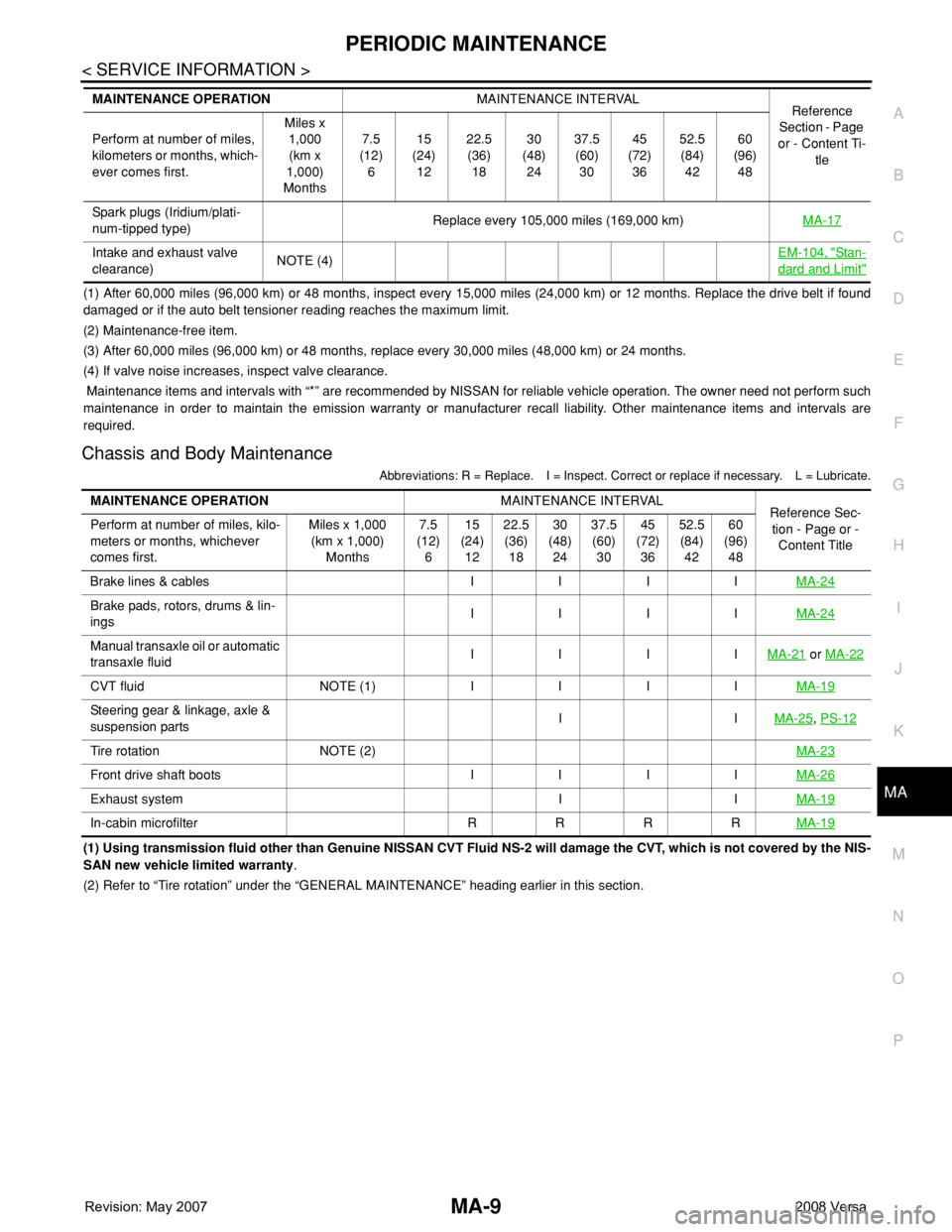
(1) After 60,000 miles (96,000 km) or 48 months, inspect every 15,000 miles (24,000 km) or 12 months. Replace the drive belt if found
damaged or if the auto belt tensioner reading reaches the maximum limit.
(2) Maintenance-free item.
(3) After 60,000 miles (96,000 km) or 48 months, replace every 30,000 miles (48,000 km) or 24 months.
(4) If valve noise increases, inspect valve clearance.
Maintenance items and intervals with “*” are recommended by NISSAN for reliable vehicle operation. The owner need not perform such
maintenance in order to maintain the emission warranty or manufacturer recall liability. Other maintenance items and intervals are
required.
Chassis and Body Maintenance
Abbreviations: R = Replace. I = Inspect. Correct or replace if necessary. L = Lubricate.
(1) Using transmission fluid other than Genuine NISSAN CVT Fluid NS-2 will damage the CVT, which is not covered by the NIS-
SAN new vehicle limited warranty.
(2) Refer to “Tire rotation” under the “GENERAL MAINTENANCE” heading earlier in this section. Spark plugs (Iridium/plati-
num-tipped type)Replace every 105,000 miles (169,000 km)MA-17
Intake and exhaust valve
clearance)NOTE (4)EM-104, "Sta n-
dard and Limit"
MAINTENANCE OPERATIONMAINTENANCE INTERVAL
Reference
Section - Page
or - Content Ti-
tle Perform at number of miles,
kilometers or months, which-
ever comes first.Miles x
1,000
(km x
1,000)
Months7.5
(12)
615
(24)
1222.5
(36)
1830
(48)
2437.5
(60)
3045
(72)
3652.5
(84)
4260
(96)
48
MAINTENANCE OPERATIONMAINTENANCE INTERVAL
Reference Sec-
tion - Page or -
Content Title Perform at number of miles, kilo-
meters or months, whichever
comes first.Miles x 1,000
(km x 1,000)
Months7.5
(12)
615
(24)
1222.5
(36)
1830
(48)
2437.5
(60)
3045
(72)
3652.5
(84)
4260
(96)
48
Brake lines & cables I I I IMA-24
Brake pads, rotors, drums & lin-
ings IIIIMA-24
Manual transaxle oil or automatic
transaxle fluidIIIIMA-21 or MA-22
CVT fluid NOTE (1) IIIIMA-19
Steering gear & linkage, axle &
suspension partsIIMA-25, PS-12
Tire rotation NOTE (2)MA-23
Front drive shaft boots I I I IMA-26
Exhaust system I IMA-19
In-cabin microfilter R R R RMA-19