2008 NISSAN TIIDA Break
[x] Cancel search: BreakPage 20 of 2771
AT-8
< SERVICE INFORMATION >
PRECAUTIONS
• Be sure to turn the ignition switch OFF and disconnect battery negative cable from battery negative
terminal before any repair or inspection work. The open/short circuit of related switches, sensors,
solenoid valves, etc. will cause the MIL to light up.
• Be sure to connect and lock the connectors securely after work. A loose (unlocked) connector will
cause the MIL to light up due to an open circuit. (Be sure the connectors are free from water, grease,
dirt, bent terminals, etc.)
• Be sure to route and secure the harnesses properly after work. Interference of the harness with a
bracket, etc. may cause the MIL to light up due to a short circuit.
• Be sure to erase the unnecessary malfunction information (repairs completed) from the TCM and
ECM before returning the vehicle to the customer.
PrecautionINFOID:0000000001703154
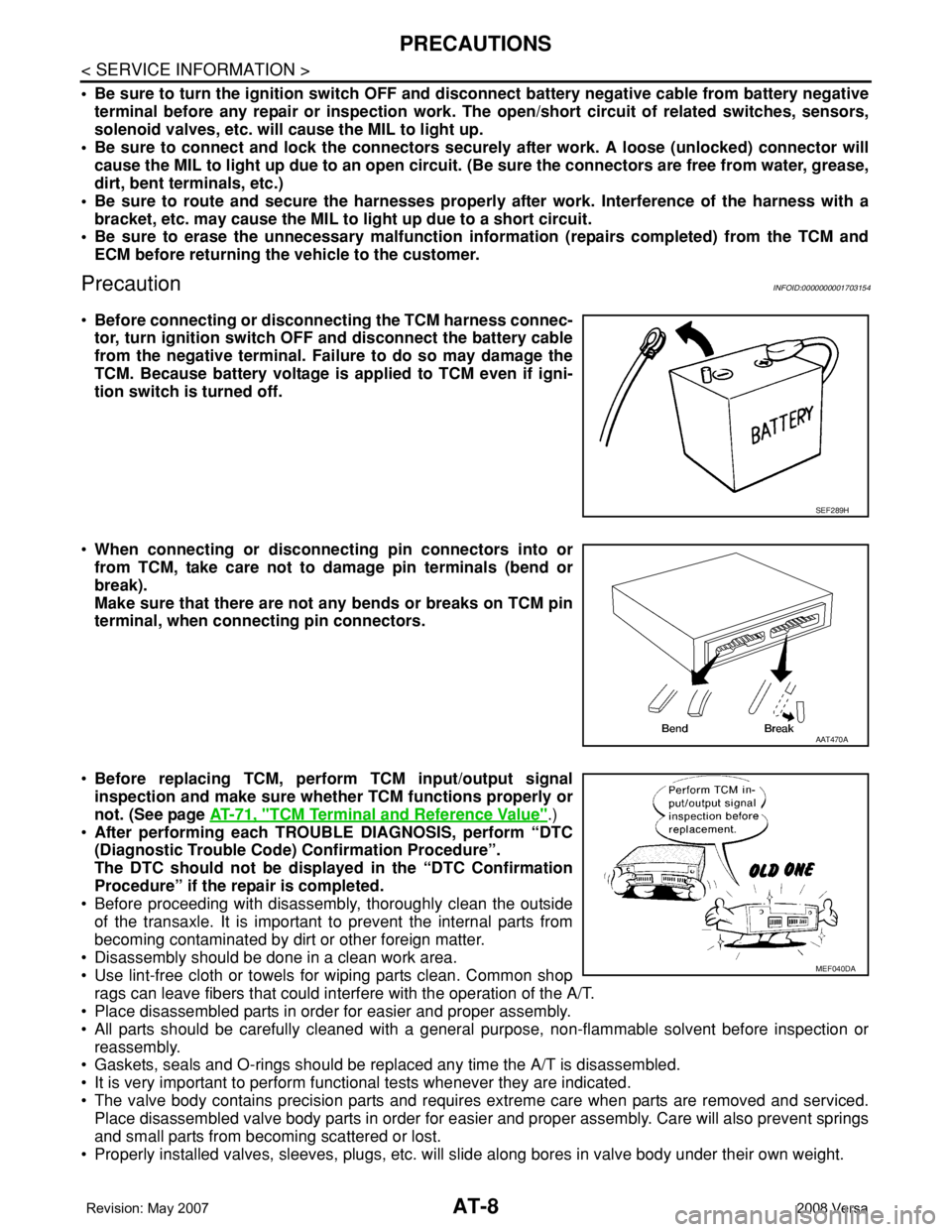
•Before connecting or disconnecting the TCM harness connec-
tor, turn ignition switch OFF and disconnect the battery cable
from the negative terminal. Failure to do so may damage the
TCM. Because battery voltage is applied to TCM even if igni-
tion switch is turned off.
•When connecting or disconnecting pin connectors into or
from TCM, take care not to damage pin terminals (bend or
break).
Make sure that there are not any bends or breaks on TCM pin
terminal, when connecting pin connectors.
•Before replacing TCM, perform TCM input/output signal
inspection and make sure whether TCM functions properly or
not. (See page AT-71, "
TCM Terminal and Reference Value".)
•After performing each TROUBLE DIAGNOSIS, perform “DTC
(Diagnostic Trouble Code) Confirmation Procedure”.
The DTC should not be displayed in the “DTC Confirmation
Procedure” if the repair is completed.
• Before proceeding with disassembly, thoroughly clean the outside
of the transaxle. It is important to prevent the internal parts from
becoming contaminated by dirt or other foreign matter.
• Disassembly should be done in a clean work area.
• Use lint-free cloth or towels for wiping parts clean. Common shop
rags can leave fibers that could interfere with the operation of the A/T.
• Place disassembled parts in order for easier and proper assembly.
• All parts should be carefully cleaned with a general purpose, non-flammable solvent before inspection or
reassembly.
• Gaskets, seals and O-rings should be replaced any time the A/T is disassembled.
• It is very important to perform functional tests whenever they are indicated.
• The valve body contains precision parts and requires extreme care when parts are removed and serviced.
Place disassembled valve body parts in order for easier and proper assembly. Care will also prevent springs
and small parts from becoming scattered or lost.
• Properly installed valves, sleeves, plugs, etc. will slide along bores in valve body under their own weight.
SEF289H
AAT470A
MEF040DA
Page 240 of 2771
AT-228
< SERVICE INFORMATION >
TRANSAXLE ASSEMBLY
• When replacing an engine or transmission you must make sure any dowels are installed correctly
during re-assembly.
• Improper alignment caused by missing dowels may cause vibration, oil leaks or breakage of drive
train components.
• Do not reuse O-rings and copper washers. Refer to "COMPONENTS".
• When turning crankshaft, turn it clockwise as viewed from the front of the engine.
• When tightening the bolts for the torque converter while securing the crankshaft pulley bolt, be sure
to confirm the tightening torque of the crankshaft pulley bolt. Refer to EM-37
.
• After converter is installed to drive plate, rotate crankshaft several turns to check that transaxle
rotates freely without binding.
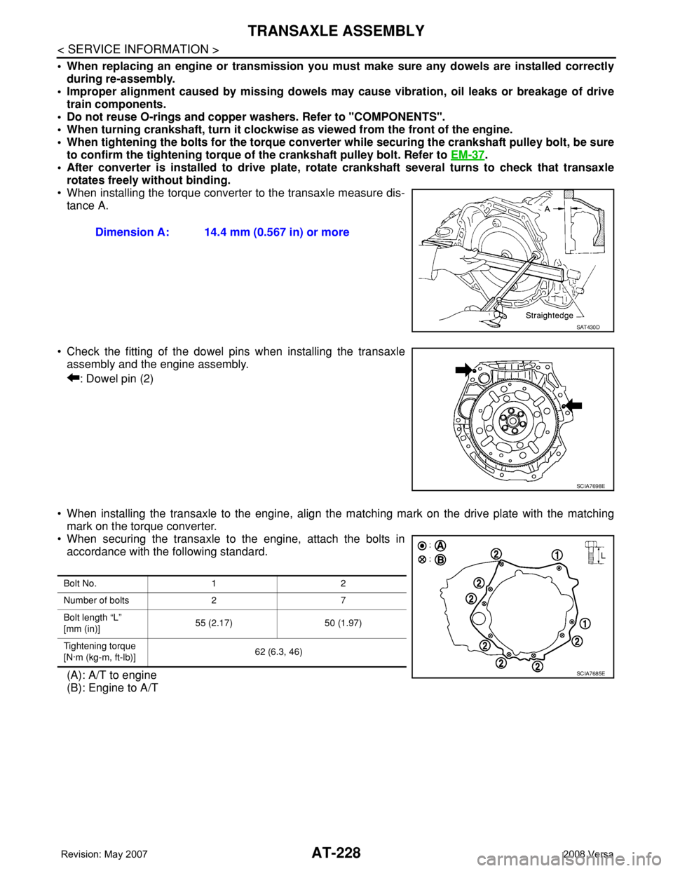
• When installing the torque converter to the transaxle measure dis-
tance A.
• Check the fitting of the dowel pins when installing the transaxle
assembly and the engine assembly.
: Dowel pin (2)
• When installing the transaxle to the engine, align the matching mark on the drive plate with the matching
mark on the torque converter.
• When securing the transaxle to the engine, attach the bolts in
accordance with the following standard.
(A): A/T to engine
(B): Engine to A/TDimension A: 14.4 mm (0.567 in) or more
SAT430D
SCIA7698E
Bolt No. 1 2
Number of bolts 2 7
Bolt length “L”
[mm (in)]55 (2.17) 50 (1.97)
Tightening torque
[N·m (kg-m, ft-lb)]62 (6.3, 46)
SCIA7685E
Page 815 of 2771
CL-14
< SERVICE INFORMATION >
CLUTCH DISC, CLUTCH COVER AND FLYWHEEL
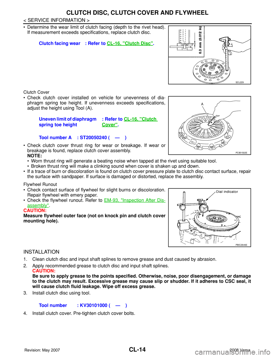
• Determine the wear limit of clutch facing (depth to the rivet head).
If measurement exceeds specifications, replace clutch disc.
Clutch Cover
• Check clutch cover installed on vehicle for unevenness of dia-
phragm spring toe height. If unevenness exceeds specifications,
adjust the height using Tool (A).
• Check clutch cover thrust ring for wear or breakage. If wear or
breakage is found, replace clutch cover assembly.
NOTE:
• Worn thrust ring will generate a beating noise when tapped at the rivet using suitable tool.
• Broken thrust ring will make a clinking sound when cover is shaken up and down.
• If a trace of burn or discoloration is found on clutch cover pressure plate to clutch disc contact surface, repair
the surface with sandpaper. If surface is damaged or distorted, replace the assembly.
Flywheel Runout
• Check contact surface of flywheel for slight burns or discoloration.
Repair flywheel with emery paper.
• Check the flywheel runout. Refer to EM-93, "
Inspection After Dis-
assembly".
CAUTION:
Measure flywheel outer face (not on knock pin and clutch cover
mounting hole).
INSTALLATION
1. Clean clutch disc and input shaft splines to remove grease and dust caused by abrasion.
2. Apply recommended grease to clutch disc and input shaft splines.
CAUTION:
Be sure to apply grease to the points specified. Otherwise, noise, poor disengagement, or damage
to the clutch may result. Excessive grease may cause slip or shudder. If it adheres to CSC seal, it
will cause clutch fluid leakage. Wipe off excess grease.
3. Install clutch disc using tool.
4. Install clutch cover. Pre-tighten clutch cover bolts.Clutch facing wear : Refer to CL-16, "
Clutch Disc".
SCL229
Uneven limit of diaphragm
spring toe height: Refer to CL-16, "Clutch
Cover".
Tool number A : ST20050240 ( — )
PCIB1502E
PBIC2646E
Tool number : KV30101000 ( — )
Page 820 of 2771
PRECAUTIONS
CO-3
< SERVICE INFORMATION >
C
D
E
F
G
H
I
J
K
L
MA
CO
N
P O
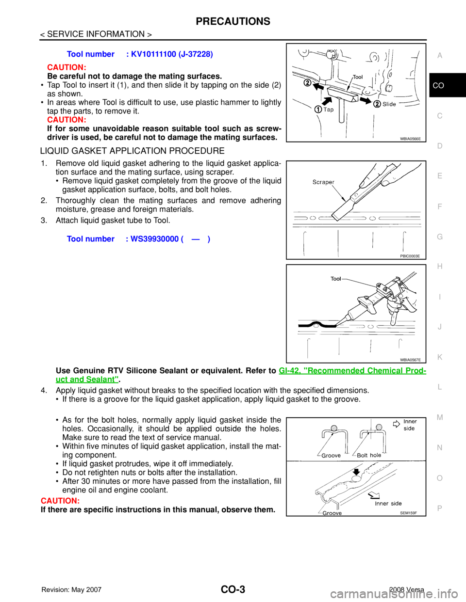
CAUTION:
Be careful not to damage the mating surfaces.
• Tap Tool to insert it (1), and then slide it by tapping on the side (2)
as shown.
• In areas where Tool is difficult to use, use plastic hammer to lightly
tap the parts, to remove it.
CAUTION:
If for some unavoidable reason suitable tool such as screw-
driver is used, be careful not to damage the mating surfaces.
LIQUID GASKET APPLICATION PROCEDURE
1. Remove old liquid gasket adhering to the liquid gasket applica-
tion surface and the mating surface, using scraper.
• Remove liquid gasket completely from the groove of the liquid
gasket application surface, bolts, and bolt holes.
2. Thoroughly clean the mating surfaces and remove adhering
moisture, grease and foreign materials.
3. Attach liquid gasket tube to Tool.
Use Genuine RTV Silicone Sealant or equivalent. Refer to GI-42, "
Recommended Chemical Prod-
uct and Sealant".
4. Apply liquid gasket without breaks to the specified location with the specified dimensions.
• If there is a groove for the liquid gasket application, apply liquid gasket to the groove.
• As for the bolt holes, normally apply liquid gasket inside the
holes. Occasionally, it should be applied outside the holes.
Make sure to read the text of service manual.
• Within five minutes of liquid gasket application, install the mat-
ing component.
• If liquid gasket protrudes, wipe it off immediately.
• Do not retighten nuts or bolts after the installation.
• After 30 minutes or more have passed from the installation, fill
engine oil and engine coolant.
CAUTION:
If there are specific instructions in this manual, observe them. Tool number : KV10111100 (J-37228)
WBIA0566E
Tool number : WS39930000 ( — )
PBIC0003E
WBIA0567E
SEM159F
Page 849 of 2771
CVT-10
< SERVICE INFORMATION >
PRECAUTIONS
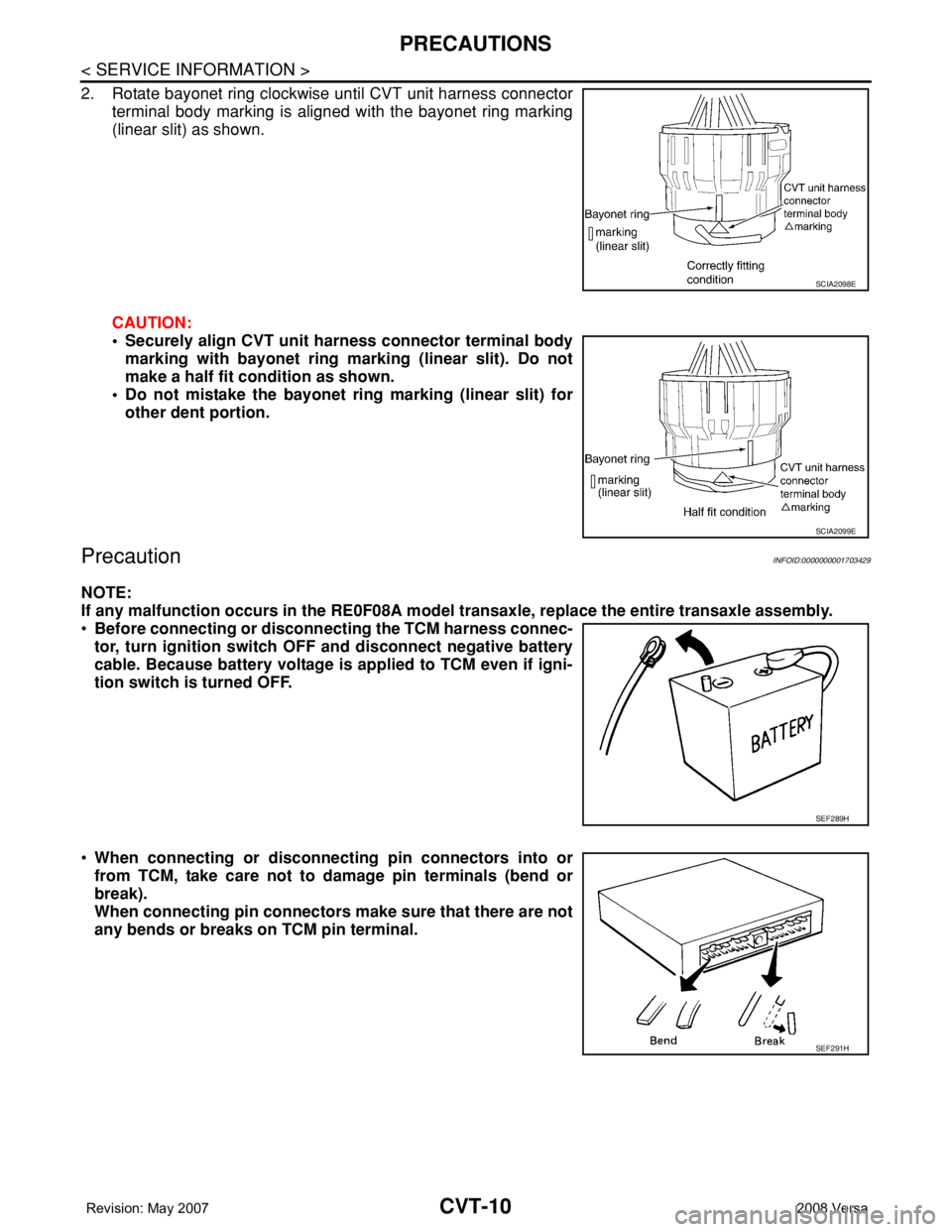
2. Rotate bayonet ring clockwise until CVT unit harness connector
terminal body marking is aligned with the bayonet ring marking
(linear slit) as shown.
CAUTION:
• Securely align CVT unit harness connector terminal body
marking with bayonet ring marking (linear slit). Do not
make a half fit condition as shown.
• Do not mistake the bayonet ring marking (linear slit) for
other dent portion.
PrecautionINFOID:0000000001703429
NOTE:
If any malfunction occurs in the RE0F08A model transaxle, replace the entire transaxle assembly.
•Before connecting or disconnecting the TCM harness connec-
tor, turn ignition switch OFF and disconnect negative battery
cable. Because battery voltage is applied to TCM even if igni-
tion switch is turned OFF.
•When connecting or disconnecting pin connectors into or
from TCM, take care not to damage pin terminals (bend or
break).
When connecting pin connectors make sure that there are not
any bends or breaks on TCM pin terminal.
SCIA2098E
SCIA2099E
SEF289H
SEF291H
Page 1018 of 2771
TRANSAXLE ASSEMBLY
CVT-179
< SERVICE INFORMATION >
D
E
F
G
H
I
J
K
L
MA
B
CVT
N
O
P
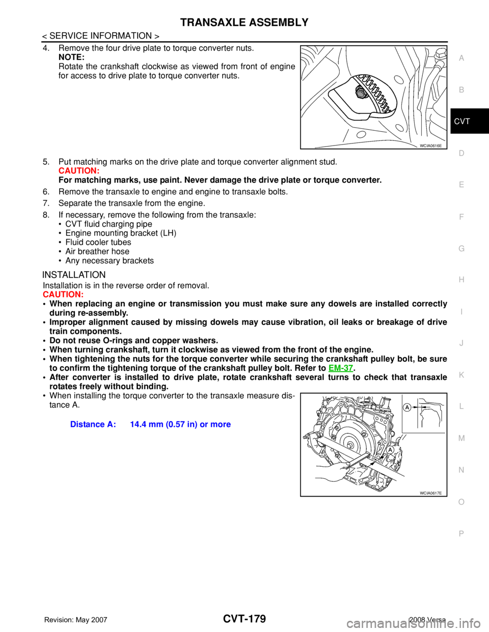
4. Remove the four drive plate to torque converter nuts.
NOTE:
Rotate the crankshaft clockwise as viewed from front of engine
for access to drive plate to torque converter nuts.
5. Put matching marks on the drive plate and torque converter alignment stud.
CAUTION:
For matching marks, use paint. Never damage the drive plate or torque converter.
6. Remove the transaxle to engine and engine to transaxle bolts.
7. Separate the transaxle from the engine.
8. If necessary, remove the following from the transaxle:
• CVT fluid charging pipe
• Engine mounting bracket (LH)
• Fluid cooler tubes
• Air breather hose
• Any necessary brackets
INSTALLATION
Installation is in the reverse order of removal.
CAUTION:
• When replacing an engine or transmission you must make sure any dowels are installed correctly
during re-assembly.
• Improper alignment caused by missing dowels may cause vibration, oil leaks or breakage of drive
train components.
• Do not reuse O-rings and copper washers.
• When turning crankshaft, turn it clockwise as viewed from the front of the engine.
• When tightening the nuts for the torque converter while securing the crankshaft pulley bolt, be sure
to confirm the tightening torque of the crankshaft pulley bolt. Refer to EM-37
.
• After converter is installed to drive plate, rotate crankshaft several turns to check that transaxle
rotates freely without binding.
• When installing the torque converter to the transaxle measure dis-
tance A.
WCIA0616E
Distance A: 14.4 mm (0.57 in) or more
WCIA0617E
Page 1091 of 2771
PRECAUTIONS
EC-17
< SERVICE INFORMATION >
C
D
E
F
G
H
I
J
K
L
MA
EC
N
P O
PrecautionINFOID:0000000001702551
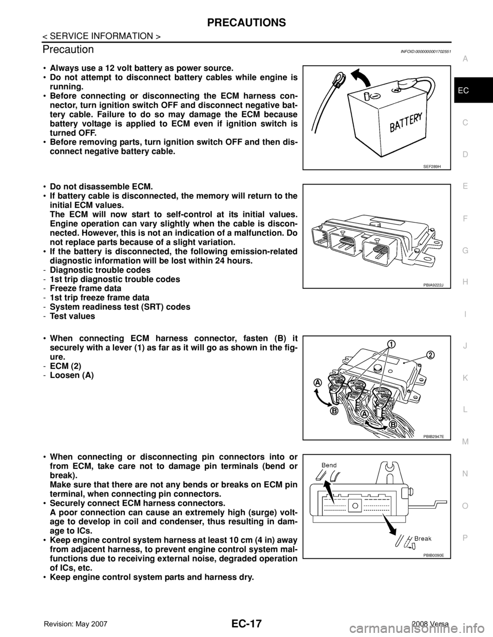
•Always use a 12 volt battery as power source.
•Do not attempt to disconnect battery cables while engine is
running.
•Before connecting or disconnecting the ECM harness con-
nector, turn ignition switch OFF and disconnect negative bat-
tery cable. Failure to do so may damage the ECM because
battery voltage is applied to ECM even if ignition switch is
turned OFF.
•Before removing parts, turn ignition switch OFF and then dis-
connect negative battery cable.
•Do not disassemble ECM.
•If battery cable is disconnected, the memory will return to the
initial ECM values.
The ECM will now start to self-control at its initial values.
Engine operation can vary slightly when the cable is discon-
nected. However, this is not an indication of a malfunction. Do
not replace parts because of a slight variation.
•If the battery is disconnected, the following emission-related
diagnostic information will be lost within 24 hours.
-Diagnostic trouble codes
-1st trip diagnostic trouble codes
-Freeze frame data
-1st trip freeze frame data
-System readiness test (SRT) codes
-Test values
•When connecting ECM harness connector, fasten (B) it
securely with a lever (1) as far as it will go as shown in the fig-
ure.
-ECM (2)
-Loosen (A)
•When connecting or disconnecting pin connectors into or
from ECM, take care not to damage pin terminals (bend or
break).
Make sure that there are not any bends or breaks on ECM pin
terminal, when connecting pin connectors.
•Securely connect ECM harness connectors.
A poor connection can cause an extremely high (surge) volt-
age to develop in coil and condenser, thus resulting in dam-
age to ICs.
•Keep engine control system harness at least 10 cm (4 in) away
from adjacent harness, to prevent engine control system mal-
functions due to receiving external noise, degraded operation
of ICs, etc.
•Keep engine control system parts and harness dry.
SEF289H
PBIA9222J
PBIB2947E
PBIB0090E
Page 1208 of 2771
EC-134
< SERVICE INFORMATION >
TROUBLE DIAGNOSIS - SPECIFICATION VALUE
3. Perform EC-75, "VIN Registration".
4. Perform EC-76, "
Accelerator Pedal Released Position Learning".
5. Perform EC-76, "
Throttle Valve Closed Position Learning".
6. Perform EC-76, "
Idle Air Volume Learning".
>> GO TO 29.
25.CHECK INTAKE SYSTEM
Check for the cause of uneven air flow through mass air flow sensor. Refer to the following.
• Crushed air ducts
• Malfunctioning seal of air cleaner element
• Uneven dirt of air cleaner element
• Improper specification of intake air system
OK or NG
OK >> GO TO 27.
NG >> Repair or replace malfunctioning part, and then GO TO 26.
26.CHECK “B/FUEL SCHDL”
Select “B/FUEL SCHDL” in “DATA MONITOR (SPEC)” mode, and make sure that the indication is within the
SP value.
OK or NG
OK >>INSPECTION END
NG (Less than the SP value)>>GO TO 27.
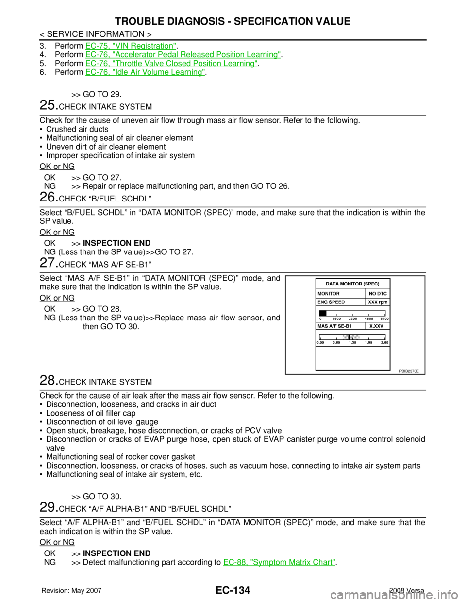
27.CHECK “MAS A/F SE-B1”
Select “MAS A/F SE-B1” in “DATA MONITOR (SPEC)” mode, and
make sure that the indication is within the SP value.
OK or NG
OK >> GO TO 28.
NG (Less than the SP value)>>Replace mass air flow sensor, and
then GO TO 30.
28.CHECK INTAKE SYSTEM
Check for the cause of air leak after the mass air flow sensor. Refer to the following.
• Disconnection, looseness, and cracks in air duct
• Looseness of oil filler cap
• Disconnection of oil level gauge
• Open stuck, breakage, hose disconnection, or cracks of PCV valve
• Disconnection or cracks of EVAP purge hose, open stuck of EVAP canister purge volume control solenoid
valve
• Malfunctioning seal of rocker cover gasket
• Disconnection, looseness, or cracks of hoses, such as vacuum hose, connecting to intake air system parts
• Malfunctioning seal of intake air system, etc.
>> GO TO 30.
29.CHECK “A/F ALPHA-B1” AND “B/FUEL SCHDL”
Select “A/F ALPHA-B1” and “B/FUEL SCHDL” in “DATA MONITOR (SPEC)” mode, and make sure that the
each indication is within the SP value.
OK or NG
OK >>INSPECTION END
NG >> Detect malfunctioning part according to EC-88, "
Symptom Matrix Chart".
PBIB2370E