2008 NISSAN TIIDA Break
[x] Cancel search: BreakPage 1818 of 2771
FAX-22
< SERVICE INFORMATION >
FRONT DRIVE SHAFT
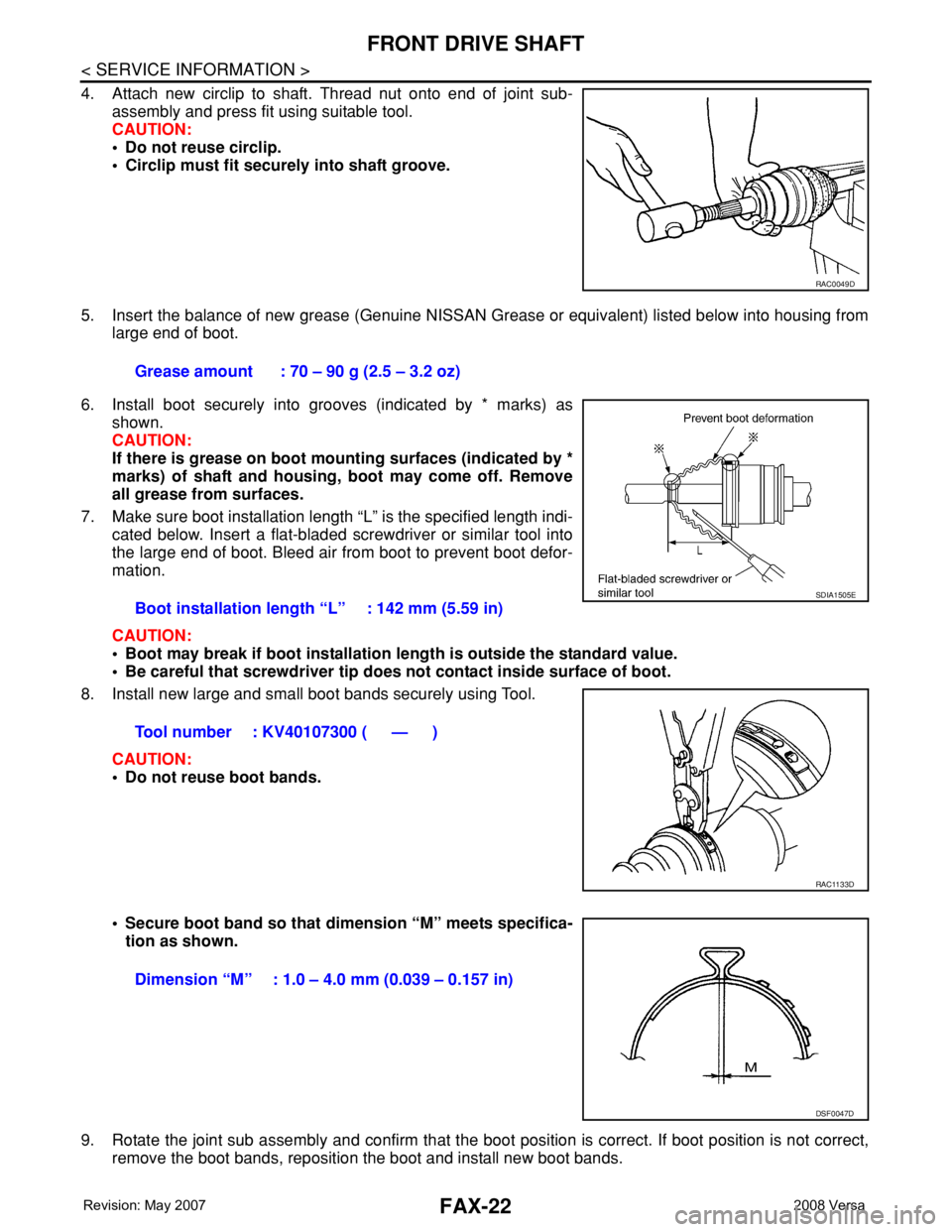
4. Attach new circlip to shaft. Thread nut onto end of joint sub-
assembly and press fit using suitable tool.
CAUTION:
• Do not reuse circlip.
• Circlip must fit securely into shaft groove.
5. Insert the balance of new grease (Genuine NISSAN Grease or equivalent) listed below into housing from
large end of boot.
6. Install boot securely into grooves (indicated by * marks) as
shown.
CAUTION:
If there is grease on boot mounting surfaces (indicated by *
marks) of shaft and housing, boot may come off. Remove
all grease from surfaces.
7. Make sure boot installation length “L” is the specified length indi-
cated below. Insert a flat-bladed screwdriver or similar tool into
the large end of boot. Bleed air from boot to prevent boot defor-
mation.
CAUTION:
• Boot may break if boot installation length is outside the standard value.
• Be careful that screwdriver tip does not contact inside surface of boot.
8. Install new large and small boot bands securely using Tool.
CAUTION:
• Do not reuse boot bands.
• Secure boot band so that dimension “M” meets specifica-
tion as shown.
9. Rotate the joint sub assembly and confirm that the boot position is correct. If boot position is not correct,
remove the boot bands, reposition the boot and install new boot bands.
RAC0049D
Grease amount : 70 – 90 g (2.5 – 3.2 oz)
Boot installation length “L” : 142 mm (5.59 in)
Tool number : KV40107300 ( — )
SDIA1505E
RAC1133D
Dimension “M” : 1.0 – 4.0 mm (0.039 – 0.157 in)
DSF0047D
Page 1961 of 2771
GW-60
< SERVICE INFORMATION >
REAR WINDOW DEFOGGER
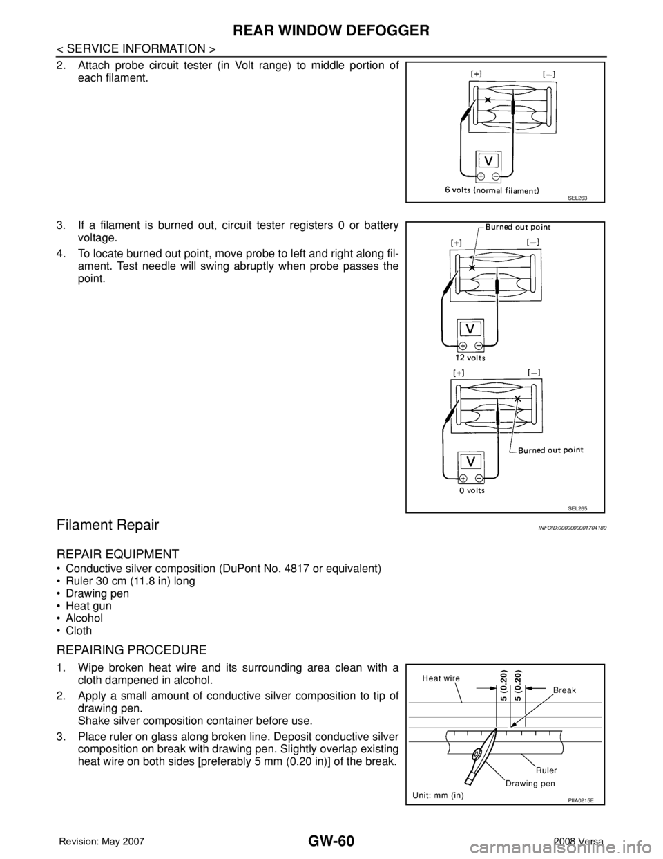
2. Attach probe circuit tester (in Volt range) to middle portion of
each filament.
3. If a filament is burned out, circuit tester registers 0 or battery
voltage.
4. To locate burned out point, move probe to left and right along fil-
ament. Test needle will swing abruptly when probe passes the
point.
Filament RepairINFOID:0000000001704180
REPAIR EQUIPMENT
• Conductive silver composition (DuPont No. 4817 or equivalent)
• Ruler 30 cm (11.8 in) long
• Drawing pen
• Heat gun
• Alcohol
• Cloth
REPAIRING PROCEDURE
1. Wipe broken heat wire and its surrounding area clean with a
cloth dampened in alcohol.
2. Apply a small amount of conductive silver composition to tip of
drawing pen.
Shake silver composition container before use.
3. Place ruler on glass along broken line. Deposit conductive silver
composition on break with drawing pen. Slightly overlap existing
heat wire on both sides [preferably 5 mm (0.20 in)] of the break.
SEL263
SEL265
PIIA0215E
Page 2434 of 2771

PG-1
ELECTRICAL
C
D
E
F
G
H
I
J
L
M
SECTION PG
A
B
PG
N
O
P
CONTENTS
POWER SUPPLY, GROUND & CIRCUIT ELEMENTS
SERVICE INFORMATION ............................2
PRECAUTIONS ...................................................2
Precaution for Supplemental Restraint System
(SRS) "AIR BAG" and "SEAT BELT PRE-TEN-
SIONER" ...................................................................
2
POWER SUPPLY ROUTING CIRCUIT ...............3
Schematic .................................................................3
Wiring Diagram - POWER - ......................................5
Fuse ........................................................................15
Fusible Link .............................................................15
Circuit Breaker (Built Into BCM) ..............................15
Circuit Breaker ........................................................15
IPDM E/R (INTELLIGENT POWER DISTRI-
BUTION MODULE ENGINE ROOM) .................
16
System Description .................................................16
CAN Communication System Description ...............17
Function of Detecting Ignition Relay Malfunction ....17
CONSULT-III Function (IPDM E/R) .........................17
Auto Active Test ......................................................19
IPDM E/R Terminal Arrangement ...........................22
Terminal and Reference Value for IPDM E/R .........23
IPDM E/R Power/Ground Circuit Inspection ...........25
Inspection with CONSULT-III (Self-Diagnosis) .......26
Removal and Installation of IPDM E/R ....................26
GROUND CIRCUIT ...........................................28
Ground Distribution ..................................................28
HARNESS .........................................................37
Harness Layout .......................................................37
Wiring Diagram Codes (Cell Codes) .......................58
ELECTRICAL UNITS LOCATION ....................61
Electrical Units Location ..........................................61
HARNESS CONNECTOR .................................65
Description ...............................................................65
ELECTRICAL UNITS ........................................68
Terminal Arrangement .............................................68
STANDARDIZED RELAY .................................69
Description ...............................................................69
SUPER MULTIPLE JUNCTION (SMJ) .............71
Terminal Arrangement .............................................71
FUSE BLOCK-JUNCTION BOX (J/B) ..............72
Terminal Arrangement .............................................72
FUSE AND FUSIBLE LINK BOX ......................73
Terminal Arrangement .............................................73
Page 2448 of 2771
POWER SUPPLY ROUTING CIRCUIT
PG-15
< SERVICE INFORMATION >
C
D
E
F
G
H
I
J
L
MA
B
PG
N
O
P
FuseINFOID:0000000001704693
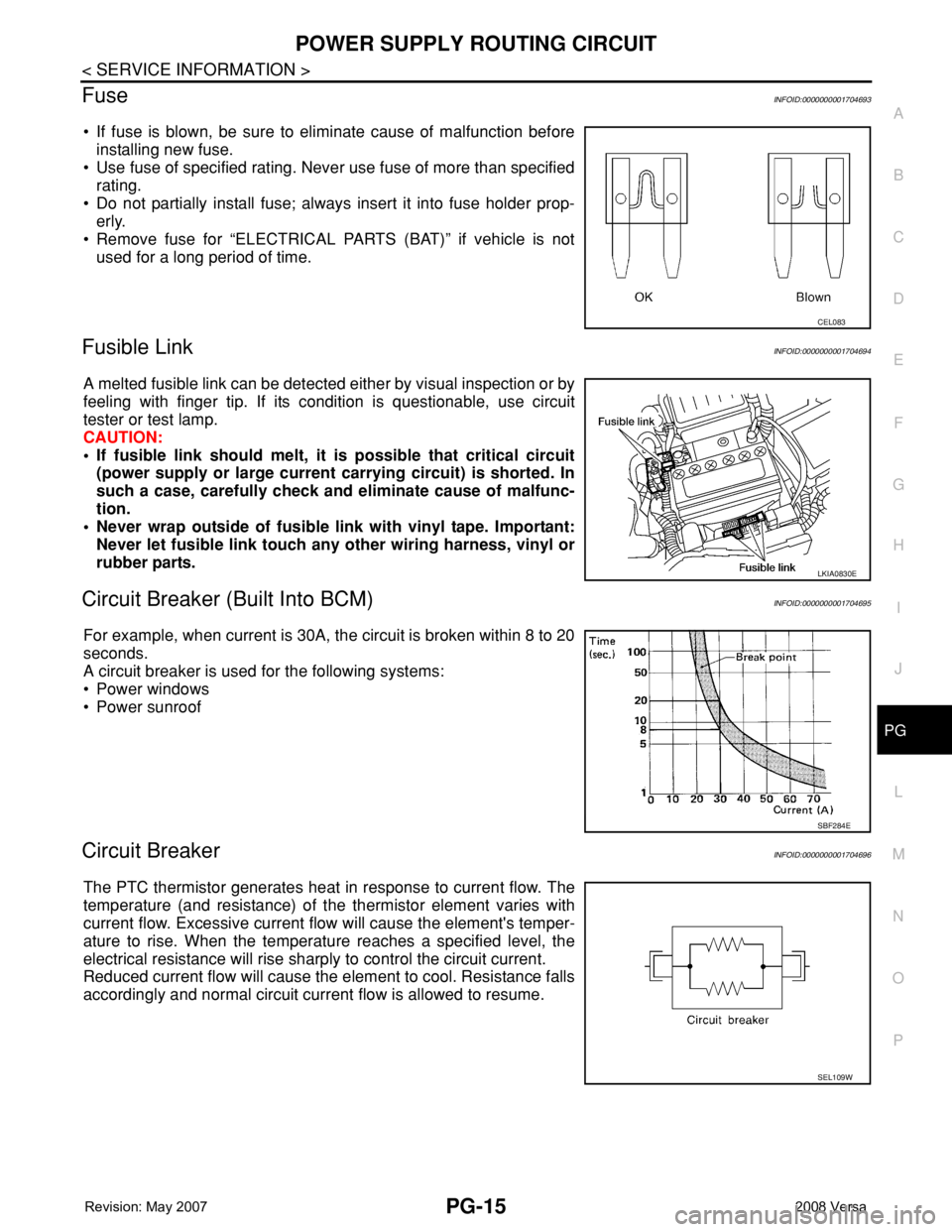
• If fuse is blown, be sure to eliminate cause of malfunction before
installing new fuse.
• Use fuse of specified rating. Never use fuse of more than specified
rating.
• Do not partially install fuse; always insert it into fuse holder prop-
erly.
• Remove fuse for “ELECTRICAL PARTS (BAT)” if vehicle is not
used for a long period of time.
Fusible LinkINFOID:0000000001704694
A melted fusible link can be detected either by visual inspection or by
feeling with finger tip. If its condition is questionable, use circuit
tester or test lamp.
CAUTION:
• If fusible link should melt, it is possible that critical circuit
(power supply or large current carrying circuit) is shorted. In
such a case, carefully check and eliminate cause of malfunc-
tion.
• Never wrap outside of fusible link with vinyl tape. Important:
Never let fusible link touch any other wiring harness, vinyl or
rubber parts.
Circuit Breaker (Built Into BCM)INFOID:0000000001704695
For example, when current is 30A, the circuit is broken within 8 to 20
seconds.
A circuit breaker is used for the following systems:
• Power windows
• Power sunroof
Circuit BreakerINFOID:0000000001704696
The PTC thermistor generates heat in response to current flow. The
temperature (and resistance) of the thermistor element varies with
current flow. Excessive current flow will cause the element's temper-
ature to rise. When the temperature reaches a specified level, the
electrical resistance will rise sharply to control the circuit current.
Reduced current flow will cause the element to cool. Resistance falls
accordingly and normal circuit current flow is allowed to resume.
CEL083
LKIA0830E
SBF284E
SEL109W
Page 2502 of 2771
STANDARDIZED RELAY
PG-69
< SERVICE INFORMATION >
C
D
E
F
G
H
I
J
L
MA
B
PG
N
O
P
STANDARDIZED RELAY
DescriptionINFOID:0000000001704713
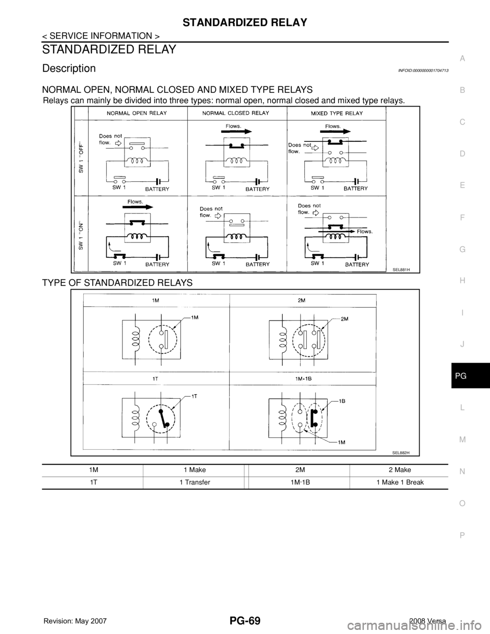
NORMAL OPEN, NORMAL CLOSED AND MIXED TYPE RELAYS
Relays can mainly be divided into three types: normal open, normal closed and mixed type relays.
TYPE OF STANDARDIZED RELAYS
SEL881H
SEL882H
1M 1 Make 2M 2 Make
1T 1 Transfer 1M·1B 1 Make 1 Break
Page 2686 of 2771
![NISSAN TIIDA 2008 Service Repair Manual PRECAUTIONS
STC-3
< SERVICE INFORMATION >[EPS]
C
D
E
F
H
I
J
K
L
MA
B
STC
N
O
P
• Check any possible causes by interviewing the symptom and it’s condition from the customer if any
malfunction, suc NISSAN TIIDA 2008 Service Repair Manual PRECAUTIONS
STC-3
< SERVICE INFORMATION >[EPS]
C
D
E
F
H
I
J
K
L
MA
B
STC
N
O
P
• Check any possible causes by interviewing the symptom and it’s condition from the customer if any
malfunction, suc](/manual-img/5/57399/w960_57399-2685.png)
PRECAUTIONS
STC-3
< SERVICE INFORMATION >[EPS]
C
D
E
F
H
I
J
K
L
MA
B
STC
N
O
P
• Check any possible causes by interviewing the symptom and it’s condition from the customer if any
malfunction, such as EPS warning lamp turns ON, occurs.
• Check if air pressure and size of tires are proper, the specified part is used for the steering wheel,
and control unit is genuine part.
• Check if the connection of steering column assembly and steering gear assembly is proper (there is
not looseness of mounting bolts, damage of rods, boots or sealants, and leakage of grease, etc).
• Check if the wheel alignment is adjusted properly.
• Check if there is any damage or modification to suspension or body resulting in increased weight or
altered ground clearance.
• Check if installation conditions of each link and suspension are proper.
• Check if the battery voltage is proper
• Check connection conditions of each connector are proper.
• Before connecting or disconnecting the EPS control unit har-
ness connector, turn ignition switch “OFF” and disconnect
battery ground cable. Because battery voltage is applied to
EPS control unit even if ignition switch is turned “OFF”.
• When connecting or disconnecting pin connectors into or
from EPS control unit, take care not to damage pin terminals
(bend or break).
When connecting pin connectors, make sure that there are no
bends or breaks on EPS control unit pin terminal.
• Before replacing EPS control unit, perform EPS control unit
input/output signal inspection and make sure whether EPS
control unit functions properly or not. Refer to STC-9, "
EPS
Control Unit Input/Output Signal Reference Value".
SEF289H
SEF291H
SDIA1848E
Page 2731 of 2771
REMOVAL AND INSTALLATION
WT-23
< SERVICE INFORMATION >
C
D
F
G
H
I
J
K
L
MA
B
WT
N
O
P
REMOVAL AND INSTALLATION
Transmitter (Pressure Sensor)INFOID:0000000001703772
REMOVAL
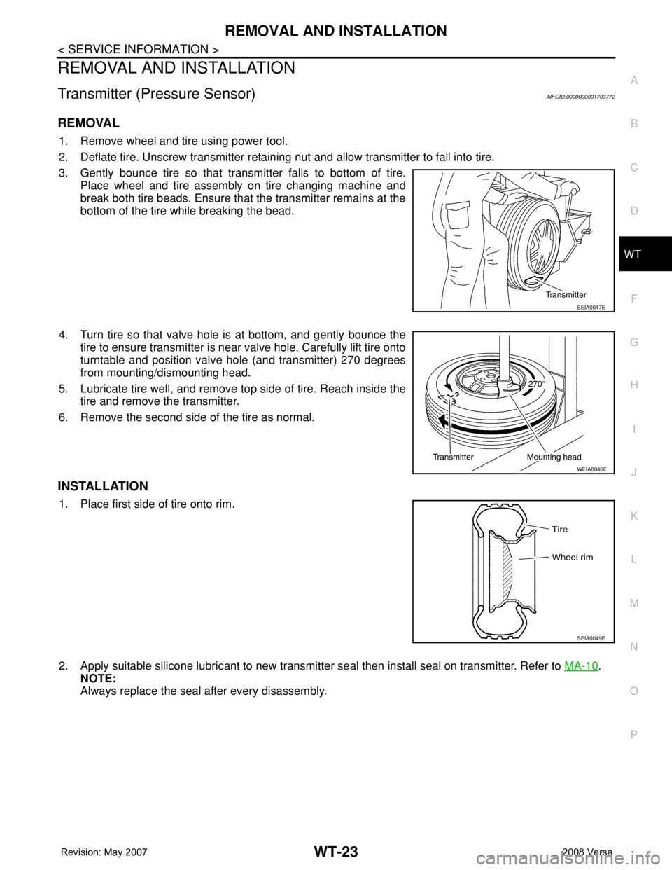
1. Remove wheel and tire using power tool.
2. Deflate tire. Unscrew transmitter retaining nut and allow transmitter to fall into tire.
3. Gently bounce tire so that transmitter falls to bottom of tire.
Place wheel and tire assembly on tire changing machine and
break both tire beads. Ensure that the transmitter remains at the
bottom of the tire while breaking the bead.
4. Turn tire so that valve hole is at bottom, and gently bounce the
tire to ensure transmitter is near valve hole. Carefully lift tire onto
turntable and position valve hole (and transmitter) 270 degrees
from mounting/dismounting head.
5. Lubricate tire well, and remove top side of tire. Reach inside the
tire and remove the transmitter.
6. Remove the second side of the tire as normal.
INSTALLATION
1. Place first side of tire onto rim.
2. Apply suitable silicone lubricant to new transmitter seal then install seal on transmitter. Refer to MA-10
.
NOTE:
Always replace the seal after every disassembly.
SEIA0047E
WEIA0046E
SEIA0049E