2008 NISSAN TIIDA Break
[x] Cancel search: BreakPage 1682 of 2771
PRECAUTIONS
EM-5
< SERVICE INFORMATION >
C
D
E
F
G
H
I
J
K
L
MA
EM
N
P O
• Do not use a torque value for final tightening.
• The torque value for these parts are for a preliminary step.
• Ensure thread and seat surfaces are clean and coated with engine oil.
Precaution for Liquid GasketINFOID:0000000001702469
REMOVAL OF LIQUID GASKET SEALING
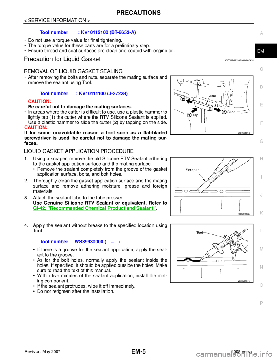
• After removing the bolts and nuts, separate the mating surface and
remove the sealant using Tool.
CAUTION:
Be careful not to damage the mating surfaces.
• In areas where the cutter is difficult to use, use a plastic hammer to
lightly tap (1) the cutter where the RTV Silicone Sealant is applied.
Use a plastic hammer to slide the cutter (2) by tapping on the side.
CAUTION:
If for some unavoidable reason a tool such as a flat-bladed
screwdriver is used, be careful not to damage the mating sur-
faces.
LIQUID GASKET APPLICATION PROCEDURE
1. Using a scraper, remove the old Silicone RTV Sealant adhering
to the gasket application surface and the mating surface.
• Remove the sealant completely from the groove of the gasket
application surface, bolts, and bolt holes.
2. Thoroughly clean the gasket application surface and the mating
surface and remove adhering moisture, grease and foreign
materials.
3. Attach the sealant tube to the tube presser.
Use Genuine Silicone RTV Sealant or equivalent. Refer to
GI-42, "
Recommended Chemical Product and Sealant".
4. Apply the sealant without breaks to the specified location using
Tool.
• If there is a groove for the sealant application, apply the seal-
ant to the groove.
• As for the bolt holes, normally apply the sealant inside the
holes. If specified, it should be applied outside the holes. Make
sure to read the text of this manual.
• Within five minutes of the sealant application, install the mat-
ing component.
• If the sealant protrudes, wipe it off immediately.
• Do not retighten after the installation.Tool number : KV10112100 (BT-8653-A)
Tool number : KV10111100 (J-37228)
WBIA0566E
PBIC0003E
Tool number WS39930000 ( – )
WBIA0567E
Page 1704 of 2771
OIL PAN
EM-27
< SERVICE INFORMATION >
C
D
E
F
G
H
I
J
K
L
MA
EM
N
P O
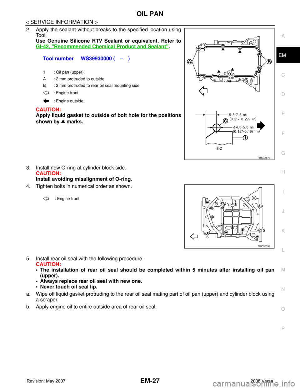
2. Apply the sealant without breaks to the specified location using
Tool.
Use Genuine Silicone RTV Sealant or equivalent. Refer to
GI-42, "
Recommended Chemical Product and Sealant".
CAUTION:
Apply liquid gasket to outside of bolt hole for the positions
shown by marks.
3. Install new O-ring at cylinder block side.
CAUTION:
Install avoiding misalignment of O-ring.
4. Tighten bolts in numerical order as shown.
5. Install rear oil seal with the following procedure.
CAUTION:
• The installation of rear oil seal should be completed within 5 minutes after installing oil pan
(upper).
• Always replace rear oil seal with new one.
• Never touch oil seal lip.
a. Wipe off liquid gasket protruding to the rear oil seal mating part of oil pan (upper) and cylinder block using
a scraper.
b. Apply engine oil to entire outside area of rear oil seal.Tool number WS39930000 ( – )
1 : Oil pan (upper)
A : 2 mm protruded to outside
B : 2 mm protruded to rear oil seal mounting side
: Engine front
: Engine outside
PBIC4587E
: Engine front
PBIC3533J
Page 1706 of 2771
OIL PAN
EM-29
< SERVICE INFORMATION >
C
D
E
F
G
H
I
J
K
L
MA
EM
N
P O
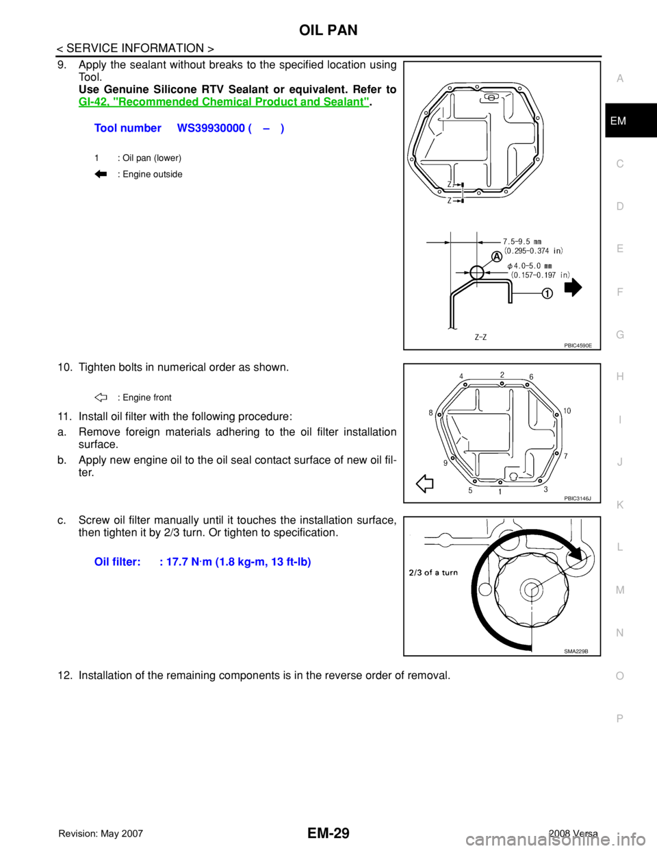
9. Apply the sealant without breaks to the specified location using
Tool.
Use Genuine Silicone RTV Sealant or equivalent. Refer to
GI-42, "
Recommended Chemical Product and Sealant".
10. Tighten bolts in numerical order as shown.
11. Install oil filter with the following procedure:
a. Remove foreign materials adhering to the oil filter installation
surface.
b. Apply new engine oil to the oil seal contact surface of new oil fil-
ter.
c. Screw oil filter manually until it touches the installation surface,
then tighten it by 2/3 turn. Or tighten to specification.
12. Installation of the remaining components is in the reverse order of removal.Tool number WS39930000 ( – )
1 : Oil pan (lower)
: Engine outside
PBIC4590E
: Engine front
PBIC3146J
Oil filter: : 17.7 N·m (1.8 kg-m, 13 ft-lb)
SMA229B
Page 1722 of 2771
TIMING CHAIN
EM-45
< SERVICE INFORMATION >
C
D
E
F
G
H
I
J
K
L
MA
EM
N
P O
Be sure O-rings a aligned properly.
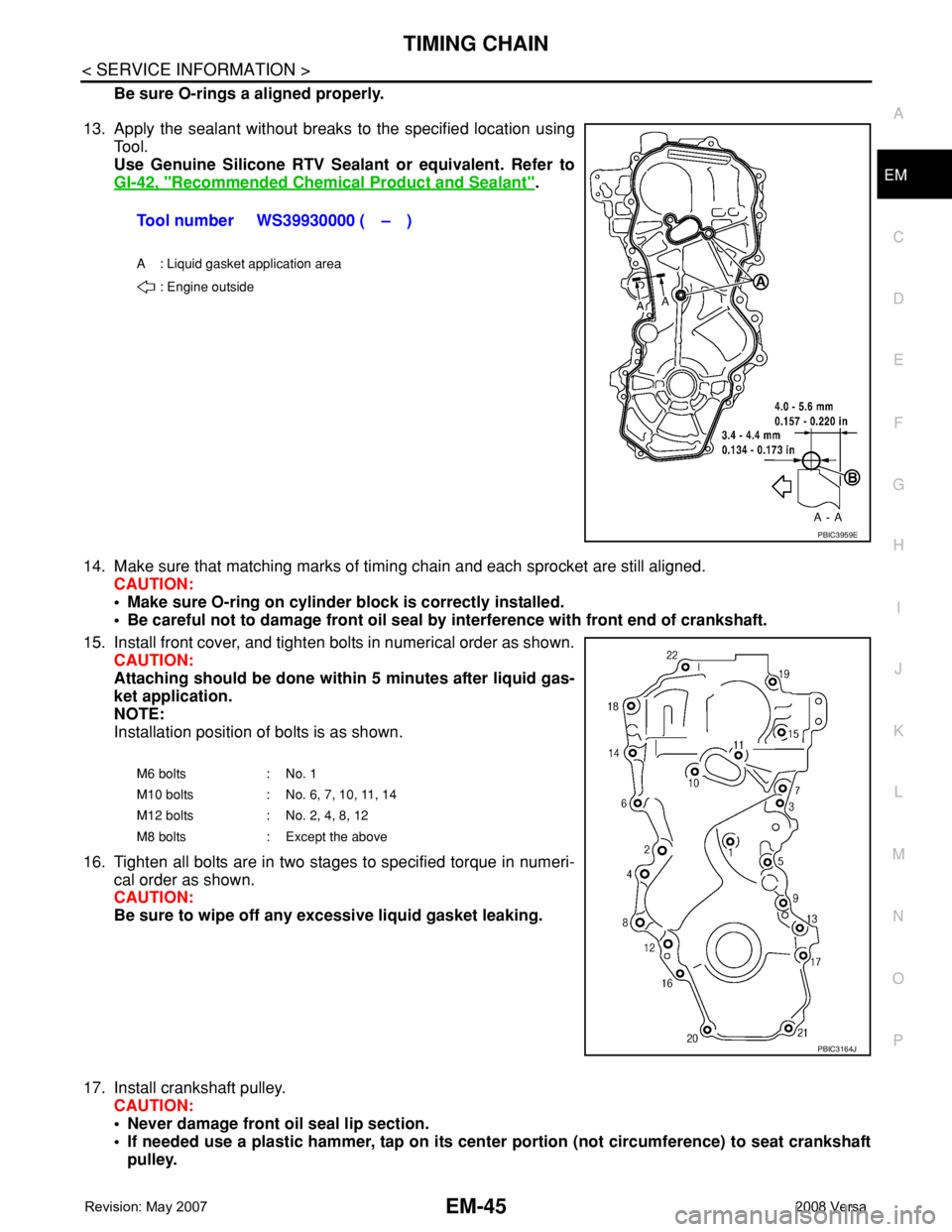
13. Apply the sealant without breaks to the specified location using
Tool.
Use Genuine Silicone RTV Sealant or equivalent. Refer to
GI-42, "
Recommended Chemical Product and Sealant".
14. Make sure that matching marks of timing chain and each sprocket are still aligned.
CAUTION:
• Make sure O-ring on cylinder block is correctly installed.
• Be careful not to damage front oil seal by interference with front end of crankshaft.
15. Install front cover, and tighten bolts in numerical order as shown.
CAUTION:
Attaching should be done within 5 minutes after liquid gas-
ket application.
NOTE:
Installation position of bolts is as shown.
16. Tighten all bolts are in two stages to specified torque in numeri-
cal order as shown.
CAUTION:
Be sure to wipe off any excessive liquid gasket leaking.
17. Install crankshaft pulley.
CAUTION:
• Never damage front oil seal lip section.
• If needed use a plastic hammer, tap on its center portion (not circumference) to seat crankshaft
pulley.Tool number WS39930000 ( – )
A : Liquid gasket application area
: Engine outside
PBIC3959E
M6 bolts : No. 1
M10 bolts : No. 6, 7, 10, 11, 14
M12 bolts : No. 2, 4, 8, 12
M8 bolts : Except the above
PBIC3164J
Page 1803 of 2771
FRONT WHEEL HUB AND KNUCKLE
FAX-7
< SERVICE INFORMATION >
C
E
F
G
H
I
J
K
L
MA
B
FA X
N
O
P
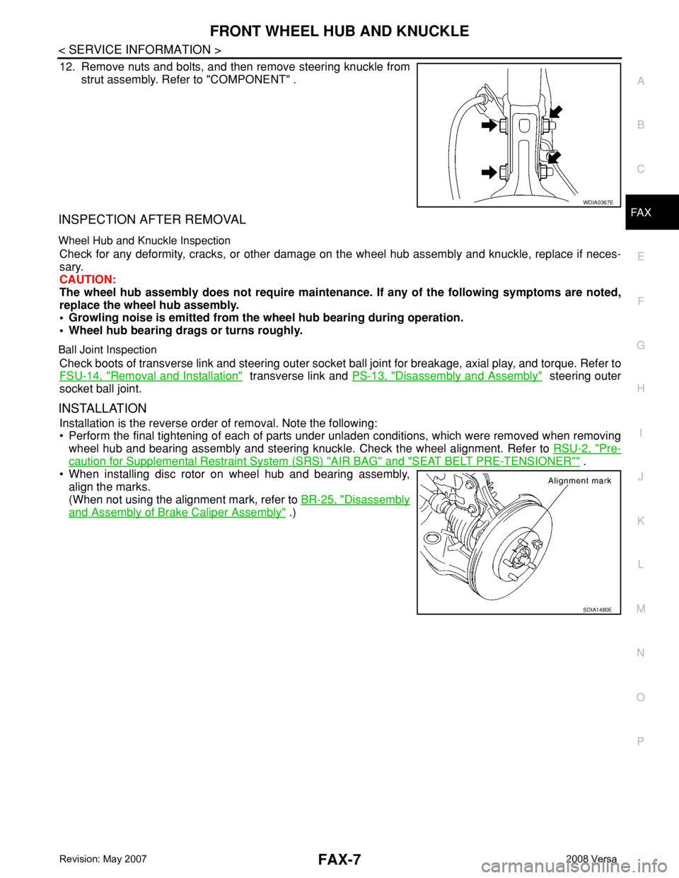
12. Remove nuts and bolts, and then remove steering knuckle from
strut assembly. Refer to "COMPONENT" .
INSPECTION AFTER REMOVAL
Wheel Hub and Knuckle Inspection
Check for any deformity, cracks, or other damage on the wheel hub assembly and knuckle, replace if neces-
sary.
CAUTION:
The wheel hub assembly does not require maintenance. If any of the following symptoms are noted,
replace the wheel hub assembly.
• Growling noise is emitted from the wheel hub bearing during operation.
• Wheel hub bearing drags or turns roughly.
Ball Joint Inspection
Check boots of transverse link and steering outer socket ball joint for breakage, axial play, and torque. Refer to
FSU-14, "
Removal and Installation" transverse link and PS-13, "Disassembly and Assembly" steering outer
socket ball joint.
INSTALLATION
Installation is the reverse order of removal. Note the following:
• Perform the final tightening of each of parts under unladen conditions, which were removed when removing
wheel hub and bearing assembly and steering knuckle. Check the wheel alignment. Refer to RSU-2, "
Pre-
caution for Supplemental Restraint System (SRS) "AIR BAG" and "SEAT BELT PRE-TENSIONER"" .
• When installing disc rotor on wheel hub and bearing assembly,
align the marks.
(When not using the alignment mark, refer to BR-25, "
Disassembly
and Assembly of Brake Caliper Assembly" .)
WDIA0367E
SDIA1480E
Page 1810 of 2771
FAX-14
< SERVICE INFORMATION >
FRONT DRIVE SHAFT
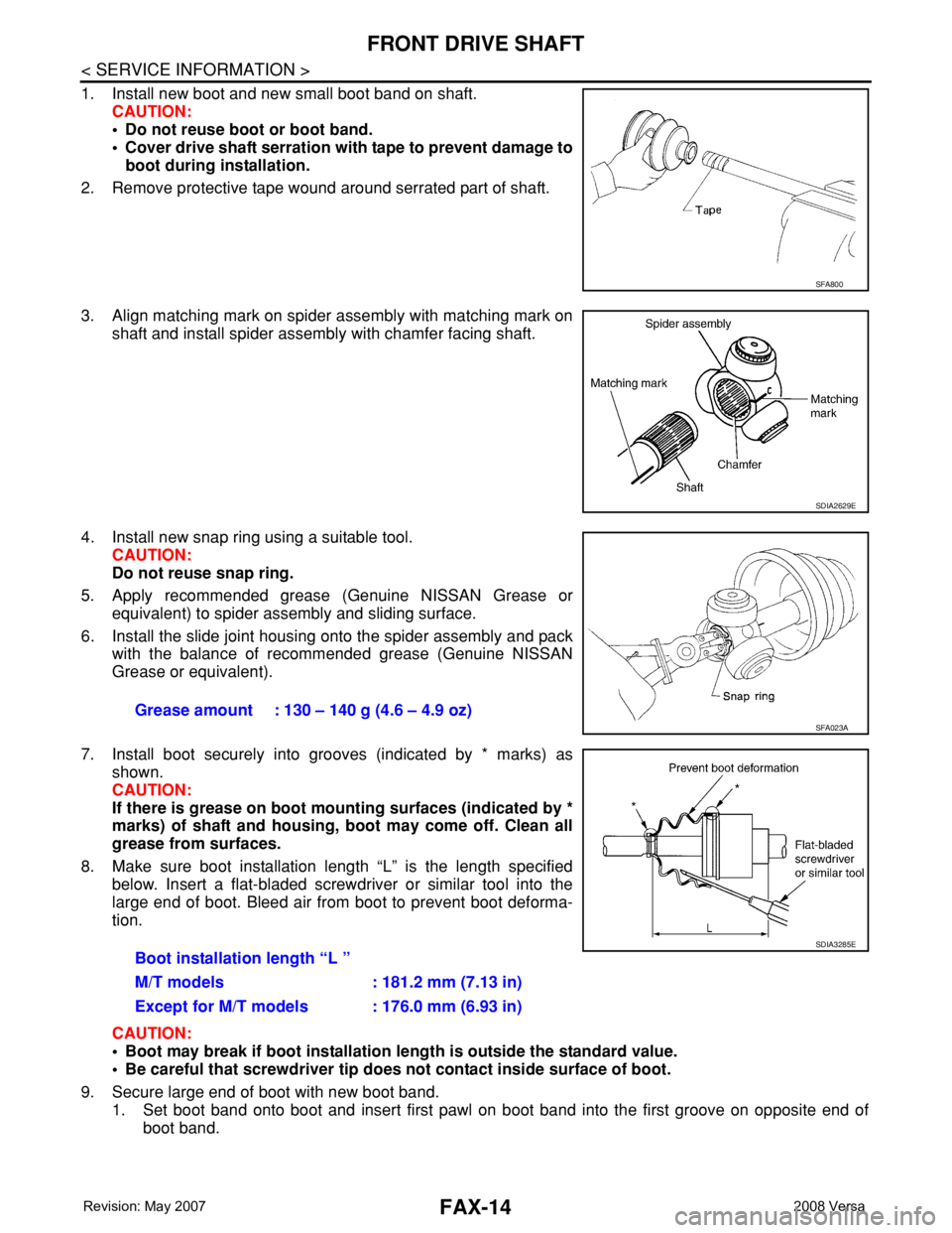
1. Install new boot and new small boot band on shaft.
CAUTION:
• Do not reuse boot or boot band.
• Cover drive shaft serration with tape to prevent damage to
boot during installation.
2. Remove protective tape wound around serrated part of shaft.
3. Align matching mark on spider assembly with matching mark on
shaft and install spider assembly with chamfer facing shaft.
4. Install new snap ring using a suitable tool.
CAUTION:
Do not reuse snap ring.
5. Apply recommended grease (Genuine NISSAN Grease or
equivalent) to spider assembly and sliding surface.
6. Install the slide joint housing onto the spider assembly and pack
with the balance of recommended grease (Genuine NISSAN
Grease or equivalent).
7. Install boot securely into grooves (indicated by * marks) as
shown.
CAUTION:
If there is grease on boot mounting surfaces (indicated by *
marks) of shaft and housing, boot may come off. Clean all
grease from surfaces.
8. Make sure boot installation length “L” is the length specified
below. Insert a flat-bladed screwdriver or similar tool into the
large end of boot. Bleed air from boot to prevent boot deforma-
tion.
CAUTION:
• Boot may break if boot installation length is outside the standard value.
• Be careful that screwdriver tip does not contact inside surface of boot.
9. Secure large end of boot with new boot band.
1. Set boot band onto boot and insert first pawl on boot band into the first groove on opposite end of
boot band.
SFA800
SDIA2629E
Grease amount : 130 – 140 g (4.6 – 4.9 oz) SFA023A
Boot installation length “L ”
M/T models : 181.2 mm (7.13 in)
Except for M/T models : 176.0 mm (6.93 in)
SDIA3285E
Page 1812 of 2771
FAX-16
< SERVICE INFORMATION >
FRONT DRIVE SHAFT
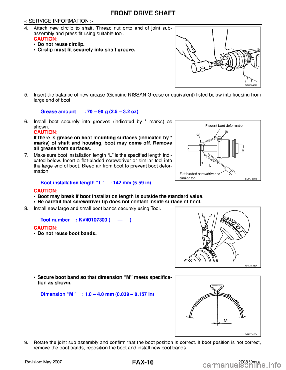
4. Attach new circlip to shaft. Thread nut onto end of joint sub-
assembly and press fit using suitable tool.
CAUTION:
• Do not reuse circlip.
• Circlip must fit securely into shaft groove.
5. Insert the balance of new grease (Genuine NISSAN Grease or equivalent) listed below into housing from
large end of boot.
6. Install boot securely into grooves (indicated by * marks) as
shown.
CAUTION:
If there is grease on boot mounting surfaces (indicated by *
marks) of shaft and housing, boot may come off. Remove
all grease from surfaces.
7. Make sure boot installation length “L” is the specified length indi-
cated below. Insert a flat-bladed screwdriver or similar tool into
the large end of boot. Bleed air from boot to prevent boot defor-
mation.
CAUTION:
• Boot may break if boot installation length is outside the standard value.
• Be careful that screwdriver tip does not contact inside surface of boot.
8. Install new large and small boot bands securely using Tool.
CAUTION:
• Do not reuse boot bands.
• Secure boot band so that dimension “M” meets specifica-
tion as shown.
9. Rotate the joint sub assembly and confirm that the boot position is correct. If boot position is not correct,
remove the boot bands, reposition the boot and install new boot bands.
RAC0049D
Grease amount : 70 – 90 g (2.5 – 3.2 oz)
Boot installation length “L” : 142 mm (5.59 in)
Tool number : KV40107300 ( — )
SDIA1505E
RAC1133D
Dimension “M” : 1.0 – 4.0 mm (0.039 – 0.157 in)
DSF0047D
Page 1816 of 2771
FAX-20
< SERVICE INFORMATION >
FRONT DRIVE SHAFT
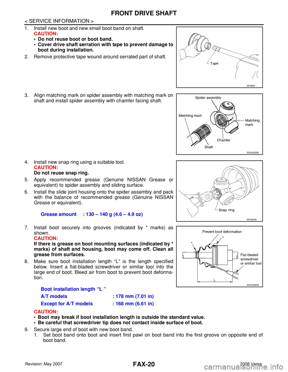
1. Install new boot and new small boot band on shaft.
CAUTION:
• Do not reuse boot or boot band.
• Cover drive shaft serration with tape to prevent damage to
boot during installation.
2. Remove protective tape wound around serrated part of shaft.
3. Align matching mark on spider assembly with matching mark on
shaft and install spider assembly with chamfer facing shaft.
4. Install new snap ring using a suitable tool.
CAUTION:
Do not reuse snap ring.
5. Apply recommended grease (Genuine NISSAN Grease or
equivalent) to spider assembly and sliding surface.
6. Install the slide joint housing onto the spider assembly and pack
with the balance of recommended grease (Genuine NISSAN
Grease or equivalent).
7. Install boot securely into grooves (indicated by * marks) as
shown.
CAUTION:
If there is grease on boot mounting surfaces (indicated by *
marks) of shaft and housing, boot may come off. Clean all
grease from surfaces.
8. Make sure boot installation length “L” is the length specified
below. Insert a flat-bladed screwdriver or similar tool into the
large end of boot. Bleed air from boot to prevent boot deforma-
tion.
CAUTION:
• Boot may break if boot installation length is outside the standard value.
• Be careful that screwdriver tip does not contact inside surface of boot.
9. Secure large end of boot with new boot band.
1. Set boot band onto boot and insert first pawl on boot band into the first groove on opposite end of
boot band.
SFA800
SDIA2629E
Grease amount : 130 – 140 g (4.6 – 4.9 oz) SFA023A
Boot installation length “L ”
A/T models : 178 mm (7.01 in)
Except for A/T models : 168 mm (6.61 in)
SDIA3285E