Page 2491 of 2771

PG-58
< SERVICE INFORMATION >
HARNESS
Wiring Diagram Codes (Cell Codes)
INFOID:0000000001704709
Use the chart below to find out what each wiring diagram code stands for.
Refer to the wiring diagram code in the alphabetical index to find the location (page number) of each wiring
diagram.
D3 D404 W/3 : Rear wiper motor
D4 D405 W/4 : Back door lock assembly
D4 D406 W/2 : Back door request switch
E2 D407 W/2 : High mounted stop lamp
D4 D408 BR/2 : Back door opener switch
E4 D409 B/1 : Condenser-1
C2 D410 — : Body ground
E3 D411 B/1 : Condenser-1
E1 D412 B/1 : Rear window defogger (+)
C2 D413 B/1 : Rear window defogger (-)
F3 D414 — : Body ground
Code Section Wiring Diagram Name
ABS BRC Anti-lock Brake System
A/C,M MTC Manual Air Conditioner
APPS1 EC Accelerator Pedal Position Sensor
A/F EC Air Fuel Ratio Sensor 1
A/FH EC Air Fuel Ratio Sensor 1 Heater
APPS2 EC Accelerator Pedal Position Sensor
APPS3 EC Accelerator Pedal Position Sensor
ASC/BS EC ASCD Brake Switch
ASC/SW EC ASCD Steering Switch
ASCBOF EC ASCD Brake Switch
ASCIND EC ASCD Indicator
AT/IND DI A/T Indicator Lamp
AUDIO AV Audio
BACK/L LT Back-up Lamp
BA/FTS AT A/T Fluid Temperature Sensor and TCM Power Supply
B/DOOR BL Back Door Opener
BRK/SW EC Brake Switch
CAN AT CAN Communication Line
CAN CVT CAN Communication Line
CAN EC CAN Communication Line
CAN LAN CAN System
CHARGE SC Charging System
CHIME DI Warning Chime
COOL/F EC Cooling Fan Control
COMBSW LT Combination Switch
CVTIND DI CVT Indicator Lamp
D/LOCK BL Power Door Lock
DEF GW Rear Window Defogger
DTRL LT Headlamp - With Daytime Light System
ECTS EC Engine Coolant Temperature Sensor
ENGSS AT Engine Speed Signal
EPS STC Electronic Controlled Power Steering
ETC1 EC Electric Throttle Control Function
Page 2752 of 2771

FRONT WIPER AND WASHER SYSTEM
WW-19
< SERVICE INFORMATION >
C
D
E
F
G
H
I
J
L
MA
B
WW
N
O
P
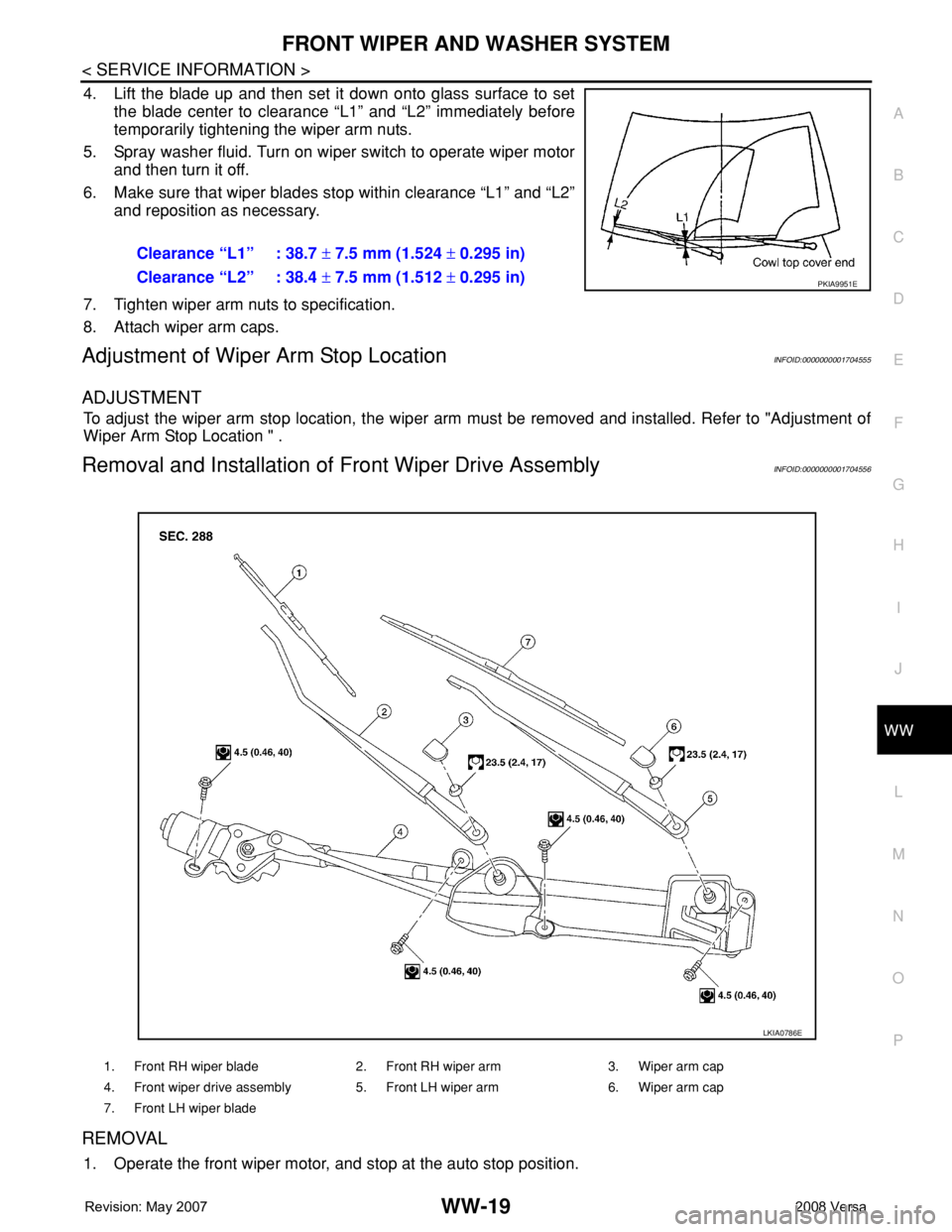
4. Lift the blade up and then set it down onto glass surface to set
the blade center to clearance “L1” and “L2” immediately before
temporarily tightening the wiper arm nuts.
5. Spray washer fluid. Turn on wiper switch to operate wiper motor
and then turn it off.
6. Make sure that wiper blades stop within clearance “L1” and “L2”
and reposition as necessary.
7. Tighten wiper arm nuts to specification.
8. Attach wiper arm caps.
Adjustment of Wiper Arm Stop LocationINFOID:0000000001704555
ADJUSTMENT
To adjust the wiper arm stop location, the wiper arm must be removed and installed. Refer to "Adjustment of
Wiper Arm Stop Location " .
Removal and Installation of Front Wiper Drive AssemblyINFOID:0000000001704556
REMOVAL
1. Operate the front wiper motor, and stop at the auto stop position.Clearance “L1” : 38.7 ± 7.5 mm (1.524 ± 0.295 in)
Clearance “L2” : 38.4 ± 7.5 mm (1.512 ± 0.295 in)
PKIA9951E
1. Front RH wiper blade 2. Front RH wiper arm 3. Wiper arm cap
4. Front wiper drive assembly 5. Front LH wiper arm 6. Wiper arm cap
7. Front LH wiper blade
LKIA0786E
Page 2755 of 2771

WW-22
< SERVICE INFORMATION >
FRONT WIPER AND WASHER SYSTEM
Removal and Installation of Front Wiper and Washer Switch
INFOID:0000000001704561
REMOVAL
1. Remove the steering column cover. Refer to IP-10 .
2. Disconnect the wiper and washer switch connector.
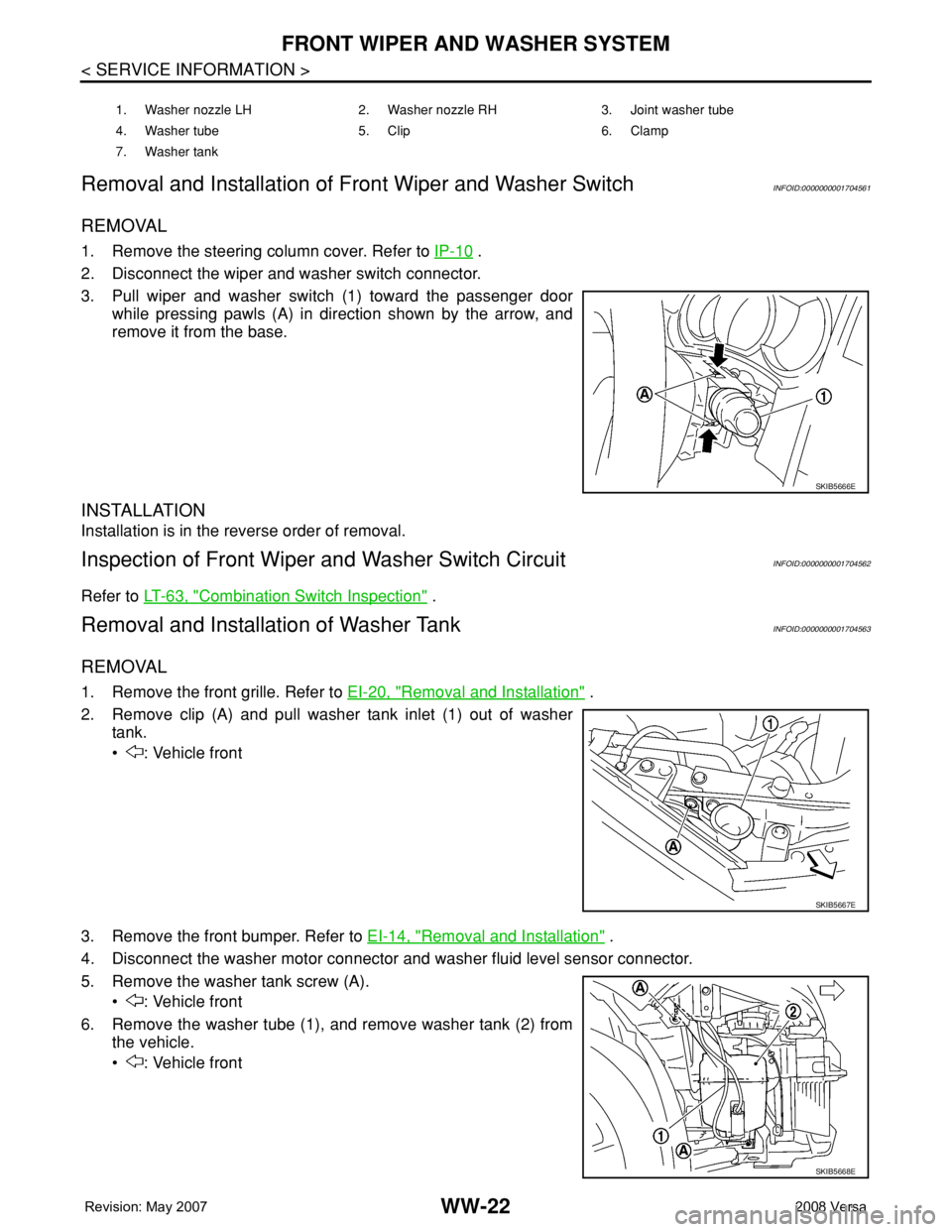
3. Pull wiper and washer switch (1) toward the passenger door
while pressing pawls (A) in direction shown by the arrow, and
remove it from the base.
INSTALLATION
Installation is in the reverse order of removal.
Inspection of Front Wiper and Washer Switch CircuitINFOID:0000000001704562
Refer to LT-63, "Combination Switch Inspection" .
Removal and Installation of Washer TankINFOID:0000000001704563
REMOVAL
1. Remove the front grille. Refer to EI-20, "Removal and Installation" .
2. Remove clip (A) and pull washer tank inlet (1) out of washer
tank.
• : Vehicle front
3. Remove the front bumper. Refer to EI-14, "
Removal and Installation" .
4. Disconnect the washer motor connector and washer fluid level sensor connector.
5. Remove the washer tank screw (A).
• : Vehicle front
6. Remove the washer tube (1), and remove washer tank (2) from
the vehicle.
• : Vehicle front
1. Washer nozzle LH 2. Washer nozzle RH 3. Joint washer tube
4. Washer tube 5. Clip 6. Clamp
7. Washer tank
SKIB5666E
SKIB5667E
SKIB5668E
Page 2766 of 2771
REAR WIPER AND WASHER SYSTEM
WW-33
< SERVICE INFORMATION >
C
D
E
F
G
H
I
J
L
MA
B
WW
N
O
P
5. Disconnect the rear wiper motor connector (B).
6. Remove the bolts (A) and remove the rear wiper motor (1).
Installation
Installation is in the reverse order of removal.
CAUTION:
Do not drop the wiper motor or cause it to contact other parts.
REAR WASHER TUBE LAYOUT
NOTE:
Connect the check valve (2) to the washer fluid tube (1) so that the
directional arrow on the check valve (2) points towards the washer
nozzle tube (3).
REAR WASHER NOZZLE
Removal
1. Remove the back door window garnish. Refer to EI-36, "Removal and Installation" .
2. Disconnect rear washer tube from rear washer nozzle.
LKIA0789E
1 Washer fluid reservoir 2 Washer fluid tube to rear door 3 Rear washer nozzle
4Check valve
LKIA0790E
WKIA4242E
Page 2767 of 2771
WW-34
< SERVICE INFORMATION >
REAR WIPER AND WASHER SYSTEM
3. Release retaining clips and remove washer nozzle.
Installation
Installation is in the reverse order of removal.
NOTE:
Inspect rear washer nozzle for proper spray pattern, adjust as necessary. Refer to WW-34, "
Washer Nozzle
Adjustment" .
WASHER FLUID RESERVOIR
Refer to WW-22, "Removal and Installation of Washer Tank" .
WIPER AND WASHER SWITCH
Refer to WW-22, "Removal and Installation of Front Wiper and Washer Switch" .
WASHER MOTOR
Refer to WW-23, "Removal and Installation of Front Washer Motor" .
Washer Nozzle AdjustmentINFOID:0000000001704578
Adjust the washer nozzle to specification using suitable tool as
shown.
LKIA0545E
Adjustable range : ±15° (In any direction)
LKIA0349E
WEL912A