2008 NISSAN TIIDA battery terminal
[x] Cancel search: battery terminalPage 10 of 2771
ACCELERATOR CONTROL SYSTEM
ACC-3
< SERVICE INFORMATION >
C
D
E
F
G
H
I
J
K
L
MA
ACC
N
P O
ACCELERATOR CONTROL SYSTEM
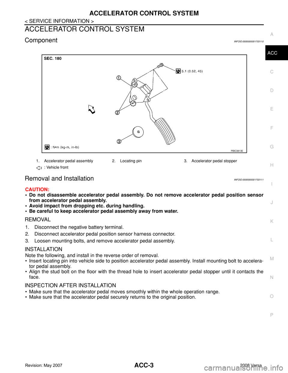
ComponentINFOID:0000000001703110
Removal and InstallationINFOID:0000000001703111
CAUTION:
• Do not disassemble accelerator pedal assembly. Do not remove accelerator pedal position sensor
from accelerator pedal assembly.
• Avoid impact from dropping etc. during handling.
• Be careful to keep accelerator pedal assembly away from water.
REMOVAL
1. Disconnect the negative battery terminal.
2. Disconnect accelerator pedal position sensor harness connector.
3. Loosen mounting bolts, and remove accelerator pedal assembly.
INSTALLATION
Note the following, and install in the reverse order of removal.
• Insert locating pin into vehicle side to position accelerator pedal assembly. Install mounting bolt to accelera-
tor pedal assembly.
• Align the stud bolt on the floor with the thread hole to insert accelerator pedal stopper until it contacts the
face.
INSPECTION AFTER INSTALLATION
• Make sure that the accelerator pedal moves smoothly within the whole operation range.
• Make sure that the accelerator pedal securely returns to the original position.
1. Accelerator pedal assembly 2. Locating pin 3. Accelerator pedal stopper
: Vehicle front
PBIC3813E
Page 13 of 2771

AT-1
TRANSMISSION/TRANSAXLE
D
E
F
G
H
I
J
K
L
M
SECTION AT
A
B
AT
N
O
P
CONTENTS
AUTOMATIC TRANSAXLE
SERVICE INFORMATION ............................5
INDEX FOR DTC .................................................5
Alphabetical Index .....................................................5
DTC No. Index ..........................................................5
PRECAUTIONS ...................................................7
Precaution for Supplemental Restraint System
(SRS) "AIR BAG" and "SEAT BELT PRE-TEN-
SIONER" ...................................................................
7
Precaution Necessary for Steering Wheel Rota-
tion After Battery Disconnect .....................................
7
Precaution for On Board Diagnosis (OBD) System
of A/T and Engine .....................................................
7
Precaution .................................................................8
Service Notice or Precaution .....................................9
PREPARATION ..................................................10
Special Service Tool ...............................................10
Commercial Service Tool ........................................13
A/T FLUID ...........................................................15
Checking A/T Fluid ..................................................15
Changing A/T Fluid .................................................15
A/T Fluid Cooler Cleaning .......................................16
A/T CONTROL SYSTEM ....................................19
Cross-Sectional View ..............................................19
Shift Mechanism ......................................................19
TCM Function ..........................................................27
CAN Communication ...............................................28
Input/Output Signal of TCM .....................................28
Line Pressure Control .............................................29
Shift Control ............................................................30
Lock-up Control .......................................................31
Engine Brake Control (Overrun Clutch Control) ......32
Control Valve ...........................................................34
Centrifugal Cancel Mechanism ...............................34
ON BOARD DIAGNOSTIC (OBD) SYSTEM ......36
Introduction .............................................................36
OBD-II Function for A/T System ..............................36
One or Two Trip Detection Logic of OBD-II .............36
OBD-II Diagnostic Trouble Code (DTC) ..................36
Malfunction Indicator Lamp (MIL) ............................38
TROUBLE DIAGNOSIS ....................................39
DTC Inspection Priority Chart ..................................39
Fail-Safe ..................................................................39
How to Perform Trouble Diagnosis for Quick and
Accurate Repair .......................................................
40
A/T Electrical Parts Location ...................................46
Circuit Diagram ........................................................47
Inspections Before Trouble Diagnosis .....................48
Road Test ................................................................52
Check Before Engine Is Started ..............................53
Check at Idle ............................................................53
Cruise Test - Part 1 .................................................55
Cruise Test - Part 2 .................................................58
Cruise Test - Part 3 .................................................59
Vehicle Speed at Which Gear Shifting Occurs ........61
Vehicle Speed at Which Lock-up Occurs/Releas-
es .............................................................................
61
Symptom Chart ........................................................61
TCM Terminal and Reference Value .......................71
CONSULT-III Function (A/T) ...................................73
Diagnosis Procedure without CONSULT-III ............78
DTC U1000 CAN COMMUNICATION LINE .....83
Description ...............................................................83
On Board Diagnosis Logic .......................................83
Possible Cause ........................................................83
DTC Confirmation Procedure ..................................83
Wiring Diagram - AT - CAN .....................................84
Diagnosis Procedure ...............................................85
DTC P0705 PARK/NEUTRAL POSITION
(PNP) SWITCH ..................................................
86
Description ...............................................................86
CONSULT-III Reference Value in Data Monitor
Mode ........................................................................
86
On Board Diagnosis Logic .......................................86
Possible Cause ........................................................86
Page 20 of 2771
AT-8
< SERVICE INFORMATION >
PRECAUTIONS
• Be sure to turn the ignition switch OFF and disconnect battery negative cable from battery negative
terminal before any repair or inspection work. The open/short circuit of related switches, sensors,
solenoid valves, etc. will cause the MIL to light up.
• Be sure to connect and lock the connectors securely after work. A loose (unlocked) connector will
cause the MIL to light up due to an open circuit. (Be sure the connectors are free from water, grease,
dirt, bent terminals, etc.)
• Be sure to route and secure the harnesses properly after work. Interference of the harness with a
bracket, etc. may cause the MIL to light up due to a short circuit.
• Be sure to erase the unnecessary malfunction information (repairs completed) from the TCM and
ECM before returning the vehicle to the customer.
PrecautionINFOID:0000000001703154
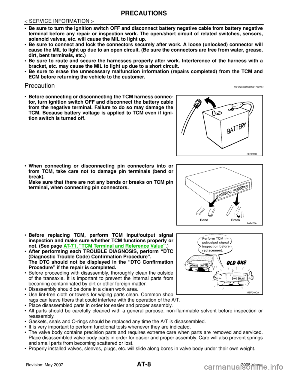
•Before connecting or disconnecting the TCM harness connec-
tor, turn ignition switch OFF and disconnect the battery cable
from the negative terminal. Failure to do so may damage the
TCM. Because battery voltage is applied to TCM even if igni-
tion switch is turned off.
•When connecting or disconnecting pin connectors into or
from TCM, take care not to damage pin terminals (bend or
break).
Make sure that there are not any bends or breaks on TCM pin
terminal, when connecting pin connectors.
•Before replacing TCM, perform TCM input/output signal
inspection and make sure whether TCM functions properly or
not. (See page AT-71, "
TCM Terminal and Reference Value".)
•After performing each TROUBLE DIAGNOSIS, perform “DTC
(Diagnostic Trouble Code) Confirmation Procedure”.
The DTC should not be displayed in the “DTC Confirmation
Procedure” if the repair is completed.
• Before proceeding with disassembly, thoroughly clean the outside
of the transaxle. It is important to prevent the internal parts from
becoming contaminated by dirt or other foreign matter.
• Disassembly should be done in a clean work area.
• Use lint-free cloth or towels for wiping parts clean. Common shop
rags can leave fibers that could interfere with the operation of the A/T.
• Place disassembled parts in order for easier and proper assembly.
• All parts should be carefully cleaned with a general purpose, non-flammable solvent before inspection or
reassembly.
• Gaskets, seals and O-rings should be replaced any time the A/T is disassembled.
• It is very important to perform functional tests whenever they are indicated.
• The valve body contains precision parts and requires extreme care when parts are removed and serviced.
Place disassembled valve body parts in order for easier and proper assembly. Care will also prevent springs
and small parts from becoming scattered or lost.
• Properly installed valves, sleeves, plugs, etc. will slide along bores in valve body under their own weight.
SEF289H
AAT470A
MEF040DA
Page 83 of 2771
TROUBLE DIAGNOSIS
AT-71
< SERVICE INFORMATION >
D
E
F
G
H
I
J
K
L
MA
B
AT
N
O
P
TCM Terminal and Reference ValueINFOID:0000000001703192
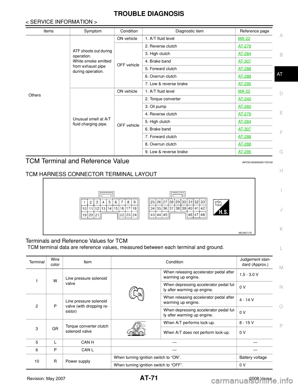
TCM HARNESS CONNECTOR TERMINAL LAYOUT
Terminals and Reference Values for TCM
TCM terminal data are reference values, measured between each terminal and ground.
OthersATF shoots out during
operation.
White smoke emitted
from exhaust pipe
during operation.ON vehicle 1. A/T fluid levelMA-22
OFF vehicle2. Reverse clutchAT- 2 7 9
3. High clutchAT- 2 8 4
4. Brake bandAT- 3 0 7
5. Forward clutchAT- 2 8 8
6. Overrun clutchAT- 2 8 8
7. Low & reverse brakeAT- 2 9 5
Unusual smell at A/T
fluid charging pipe.ON vehicle 1. A/T fluid levelMA-22
OFF vehicle2. Torque converterAT- 2 4 0
3. Oil pumpAT- 2 6 0
4. Reverse clutchAT- 2 7 9
5. High clutchAT- 2 8 4
6. Brake bandAT- 3 0 7
7. Forward clutchAT- 2 8 8
8. Overrun clutchAT- 2 8 8
9. Low & reverse brakeAT- 2 9 5
Items Symptom Condition Diagnostic item Reference page
WCIA0717E
Te r m i n a lWire
colorItem ConditionJudgement stan-
dard (Approx.)
1WLine pressure solenoid
valveWhen releasing accelerator pedal after
warming up engine.1.5 - 3.0 V
When depressing accelerator pedal ful-
ly after warming up engine.0 V
2PLine pressure solenoid
valve (with dropping re-
sistor)When releasing accelerator pedal after
warming up engine.4 - 14 V
When depressing accelerator pedal ful-
ly after warming up engine.0 V
3GRTorque converter clutch
solenoid valveWhen A/T performs lock-up. 8 - 15 V
When A/T does not perform lock-up. 0 V
5 L CAN H — —
6 P CAN L — —
10 R Power supplyWhen turning ignition switch to “ON”. Battery voltage
When turning ignition switch to “OFF”. 0 V
Page 100 of 2771

AT-88
< SERVICE INFORMATION >
DTC P0705 PARK/NEUTRAL POSITION (PNP) SWITCH
Diagnosis Procedure
INFOID:0000000001703207
1.CHECK INPUT SIGNAL
With CONSULT-III
1. Turn ignition switch ON. (Do not start engine.)
2. Select “TCM INPUT SIGNALS” in “DATA MONITOR” mode for “A/T” with CONSULT-III.
3. Read out “P·N”, “R”, “D”, “2” and “1” position switches moving selector lever to each position.
OK or NG
OK >> GO TO 6.
NG >> GO TO 3.
2.CHECK INPUT SIGNAL
Without CONSULT-III
1. Turn ignition switch ON. (Do not start engine.)
2. Check voltage between TCM connector terminals and ground
while moving selector lever through each position.
B: Battery voltage
0: 0V
OK or NG
OK >> GO TO 6.
Item name Condition Display value
PN POSI SWWhen setting selector lever to “N” or “P” posi-
tion.ON
When setting selector lever to other positions. OFF
R POSITION SWWhen setting selector lever to “R” position. ON
When setting selector lever to other positions. OFF
D POSITION SWWhen setting selector lever to “D” positions. ON
When setting selector lever to other positions. OFF
2 POSITION SWWhen setting selector lever to “2” position. ON
When setting selector lever to other positions. OFF
1 POSITION SWWhen setting selector lever to “1” position. ON
When setting selector lever to other positions. OFF
Selector lever positionTe r m i n a l
36 35 34 27 26
P, N B0000
R 0B000
D00B00
20 00B0
1 0000B
SCIA7162E
Page 110 of 2771
AT-98
< SERVICE INFORMATION >
DTC P0720 VEHICLE SPEED SENSOR A/T (REVOLUTION SENSOR)
TCM TERMINALS AND REFERENCE VALUES
Refer to AT-71, "TCM Terminal and Reference Value".
Diagnosis ProcedureINFOID:0000000001703223
1.CHECK INPUT SIGNAL
With CONSULT-III
1. Start engine.
2. Select “TCM INPUT SIGNALS” in “DATA MONITOR” mode for “A/T” with CONSULT-III.
3. Read out the value of “VHCL/S SE-A/T” while driving.
Check the value changes according to driving speed.
OK or NG
OK >> GO TO 8.
NG >> GO TO 2.
2. CHECK REVOLUTION SENSOR
With CONSULT-III
1. Start engine.
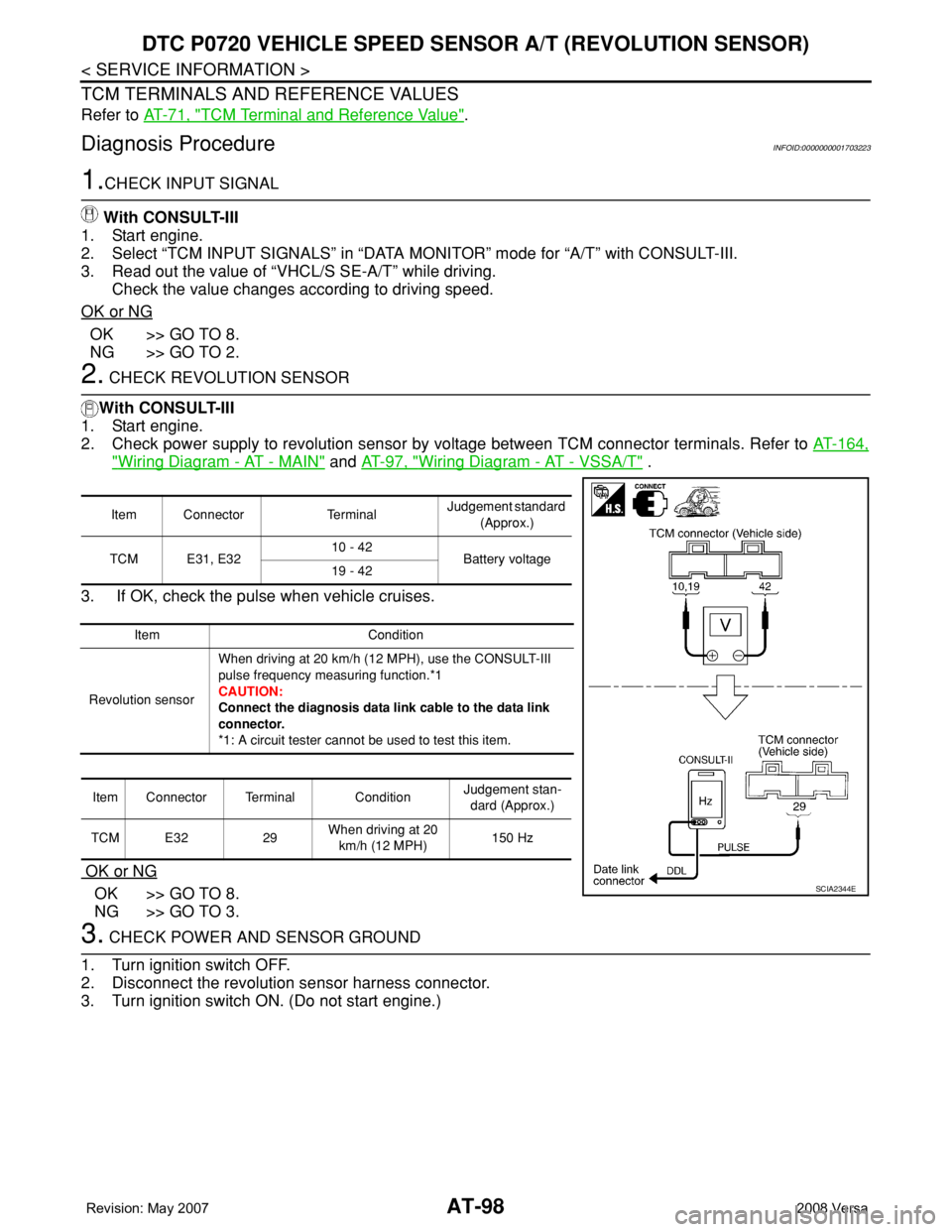
2. Check power supply to revolution sensor by voltage between TCM connector terminals. Refer to AT-164,
"Wiring Diagram - AT - MAIN" and AT-97, "Wiring Diagram - AT - VSSA/T" .
3. If OK, check the pulse when vehicle cruises.
OK or NG
OK >> GO TO 8.
NG >> GO TO 3.
3. CHECK POWER AND SENSOR GROUND
1. Turn ignition switch OFF.
2. Disconnect the revolution sensor harness connector.
3. Turn ignition switch ON. (Do not start engine.)
Item Connector TerminalJudgement standard
(Approx.)
TCM E31, E3210 - 42
Battery voltage
19 - 42
Item Condition
Revolution sensorWhen driving at 20 km/h (12 MPH), use the CONSULT-III
pulse frequency measuring function.*1
CAUTION:
Connect the diagnosis data link cable to the data link
connector.
*1: A circuit tester cannot be used to test this item.
Item Connector Terminal ConditionJudgement stan-
dard (Approx.)
TCM E32 29When driving at 20
km/h (12 MPH)150 Hz
SCIA2344E
Page 111 of 2771
DTC P0720 VEHICLE SPEED SENSOR A/T (REVOLUTION SENSOR)
AT-99
< SERVICE INFORMATION >
D
E
F
G
H
I
J
K
L
MA
B
AT
N
O
P
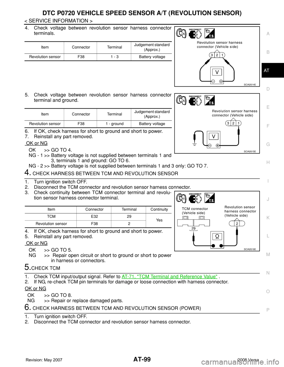
4. Check voltage between revolution sensor harness connector
terminals.
5. Check voltage between revolution sensor harness connector
terminal and ground.
6. If OK, check harness for short to ground and short to power.
7. Reinstall any part removed.
OK or NG
OK >> GO TO 4.
NG - 1 >> Battery voltage is not supplied between terminals 1 and
3, terminals 1 and ground: GO TO 6.
NG - 2 >> Battery voltage is not supplied between terminals 1 and 3 only: GO TO 7.
4. CHECK HARNESS BETWEEN TCM AND REVOLUTION SENSOR
1. Turn ignition switch OFF.
2. Disconnect the TCM connector and revolution sensor harness connector.
3. Check continuity between TCM connector terminal and revolu-
tion sensor harness connector terminal.
4. If OK, check harness for short to ground and short to power.
5. Reinstall any part removed.
OK or NG
OK >> GO TO 5.
NG >> Repair open circuit or short to ground or short to power
in harness or connectors.
5.CHECK TCM
1. Check TCM input/output signal. Refer to AT-71, "
TCM Terminal and Reference Value" .
2. If NG, re-check TCM pin terminals for damage or loose connection with harness connector.
OK or NG
OK >> GO TO 8.
NG >> Repair or replace damaged parts.
6. CHECK HARNESS BETWEEN TCM AND REVOLUTION SENSOR (POWER)
1. Turn ignition switch OFF.
2. Disconnect the TCM connector and revolution sensor harness connector.
Item Connector TerminalJudgement standard
(Approx.)
Revolution sensor F38 1 - 3 Battery voltage
SCIA2614E
Item Connector Terminal Judgement standard
(Approx.)
Revolution sensor F38 1 - ground Battery voltage
SCIA2615E
Item Connector Terminal Continuity
TCM E32 29
Ye s
Revolution sensor F38 2
SCIA2616E
Page 119 of 2771
DTC P0731 A/T 1ST GEAR FUNCTION
AT-107
< SERVICE INFORMATION >
D
E
F
G
H
I
J
K
L
MA
B
AT
N
O
P
1. Remove control valve assembly. Refer to AT-216, "Control Valve Assembly and Accumulators".
- Shift solenoid valve A
- Shift solenoid valve B
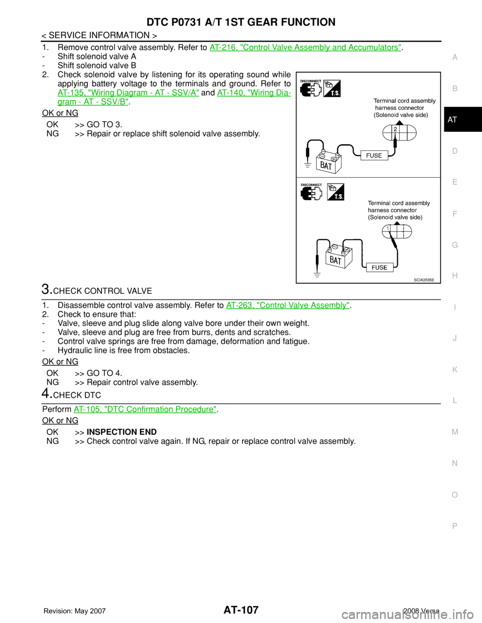
2. Check solenoid valve by listening for its operating sound while
applying battery voltage to the terminals and ground. Refer to
AT-135, "
Wiring Diagram - AT - SSV/A" and AT-140, "Wiring Dia-
gram - AT - SSV/B".
OK or NG
OK >> GO TO 3.
NG >> Repair or replace shift solenoid valve assembly.
3.CHECK CONTROL VALVE
1. Disassemble control valve assembly. Refer to AT-263, "
Control Valve Assembly".
2. Check to ensure that:
- Valve, sleeve and plug slide along valve bore under their own weight.
- Valve, sleeve and plug are free from burrs, dents and scratches.
- Control valve springs are free from damage, deformation and fatigue.
- Hydraulic line is free from obstacles.
OK or NG
OK >> GO TO 4.
NG >> Repair control valve assembly.
4.CHECK DTC
Perform AT-105, "
DTC Confirmation Procedure".
OK or NG
OK >>INSPECTION END
NG >> Check control valve again. If NG, repair or replace control valve assembly.
SCIA3595E