2008 NISSAN TIIDA Engine timing
[x] Cancel search: Engine timingPage 1075 of 2771

EC-1
ENGINE
C
D
E
F
G
H
I
J
K
L
M
SECTION EC
A
EC
N
O
P
CONTENTS
ENGINE CONTROL SYSTEM
SERVICE INFORMATION ............................9
INDEX FOR DTC .................................................9
DTC No. Index ..........................................................9
Alphabetical Index ...................................................12
PRECAUTIONS ..................................................16
Precaution for Supplemental Restraint System
(SRS) "AIR BAG" and "SEAT BELT PRE-TEN-
SIONER" .................................................................
16
Precaution for Procedure without Cowl Top Cover ....16
On Board Diagnosis (OBD) System of Engine and
A/T, CVT .................................................................
16
Precaution ...............................................................17
PREPARATION ..................................................20
Special Service Tool ...............................................20
Commercial Service Tool ........................................21
ENGINE CONTROL SYSTEM ............................22
Schematic ...............................................................22
Multiport Fuel Injection (MFI) System .....................22
Electronic Ignition (EI) System ................................25
Fuel Cut Control (at No Load and High Engine
Speed) .....................................................................
25
AIR CONDITIONING CUT CONTROL ...............27
Input/Output Signal Chart ........................................27
System Description .................................................27
AUTOMATIC SPEED CONTROL DEVICE
(ASCD) ...............................................................
28
System Description .................................................28
Component Description ...........................................29
CAN COMMUNICATION ....................................30
System Description .................................................30
EVAPORATIVE EMISSION SYSTEM ................31
Description ..............................................................31
Component Inspection ............................................33
Removal and Installation .........................................35
How to Detect Fuel Vapor Leakage .........................35
ON BOARD REFUELING VAPOR RECOV-
ERY (ORVR) ......................................................
38
System Description ..................................................38
Diagnosis Procedure ...............................................38
Component Inspection .............................................40
POSITIVE CRANKCASE VENTILATION .........43
Description ...............................................................43
Component Inspection .............................................43
NVIS (NISSAN VEHICLE IMMOBILIZER SYS-
TEM-NATS) .......................................................
45
Description ...............................................................45
ON BOARD DIAGNOSTIC (OBD) SYSTEM ....46
Introduction ..............................................................46
Two Trip Detection Logic .........................................46
Emission-related Diagnostic Information .................47
Malfunction Indicator Lamp (MIL) ............................60
OBD System Operation Chart .................................63
BASIC SERVICE PROCEDURE .......................69
Basic Inspection ......................................................69
Idle Speed and Ignition Timing Check .....................73
Procedure After Replacing ECM .............................75
VIN Registration ......................................................75
Accelerator Pedal Released Position Learning .......76
Throttle Valve Closed Position Learning .................76
Idle Air Volume Learning .........................................76
Fuel Pressure Check ...............................................78
TROUBLE DIAGNOSIS ....................................81
Trouble Diagnosis Introduction ................................81
DTC Inspection Priority Chart ..................................86
Fail-Safe Chart ........................................................87
Symptom Matrix Chart .............................................88
Engine Control Component Parts Location .............93
Vacuum Hose Drawing ............................................99
Circuit Diagram ......................................................100
ECM Harness Connector Terminal Layout ............102
Page 1098 of 2771
EC-24
< SERVICE INFORMATION >
ENGINE CONTROL SYSTEM
fuel ratio (A/F) sensor 1 in the exhaust manifold to monitor whether the engine operation is rich or lean. The
ECM adjusts the injection pulse width according to the sensor voltage signal. For more information about air
fuel ratio (A/F) sensor 1, refer to EC-213
. This maintains the mixture ratio within the range of stoichiometric
(ideal air/fuel mixture).
This stage is referred to as the closed loop control condition.
Heated oxygen sensor 2 is located downstream of the three way catalyst (manifold). Even if the switching
characteristics of air fuel ratio (A/F) sensor 1 shift, the air/fuel ratio is controlled to stoichiometric by the signal
from heated oxygen sensor 2.
Open Loop Control
The open loop system condition refers to when the ECM detects any of the following conditions. Feedback
control stops in order to maintain stabilized fuel combustion.
• Deceleration and acceleration
• High-load, high-speed operation
• Malfunction of air fuel ratio (A/F) sensor 1 or its circuit
• Insufficient activation of air fuel ratio (A/F) sensor 1 at low engine coolant temperature
• High engine coolant temperature
• During warm-up
• After shifting from N to D (A/T and CVT models)
• When starting the engine
MIXTURE RATIO SELF-LEARNING CONTROL
The mixture ratio feedback control system monitors the mixture ratio signal transmitted from air fuel ratio (A/F)
sensor 1. This feedback signal is then sent to the ECM. The ECM controls the basic mixture ratio as close to
the theoretical mixture ratio as possible. However, the basic mixture ratio is not necessarily controlled as orig-
inally designed. Both manufacturing differences (i.e., mass air flow sensor hot wire) and characteristic
changes during operation (i.e., fuel injector clogging) directly affect mixture ratio.
Accordingly, the difference between the basic and theoretical mixture ratios is monitored in this system. This is
then computed in terms of “injection pulse duration” to automatically compensate for the difference between
the two ratios.
“Fuel trim” refers to the feedback compensation value compared against the basic injection duration. Fuel trim
includes short term fuel trim and long term fuel trim.
“Short term fuel trim” is the short-term fuel compensation used to maintain the mixture ratio at its theoretical
value. The signal from air fuel ratio (A/F) sensor 1 indicates whether the mixture ratio is RICH or LEAN com-
pared to the theoretical value. The signal then triggers a reduction in fuel volume if the mixture ratio is rich, and
an increase in fuel volume if it is lean.
“Long term fuel trim” is overall fuel compensation carried out long-term to compensate for continual deviation
of the short term fuel trim from the central value. Such deviation will occur due to individual engine differences,
wear over time and changes in the usage environment.
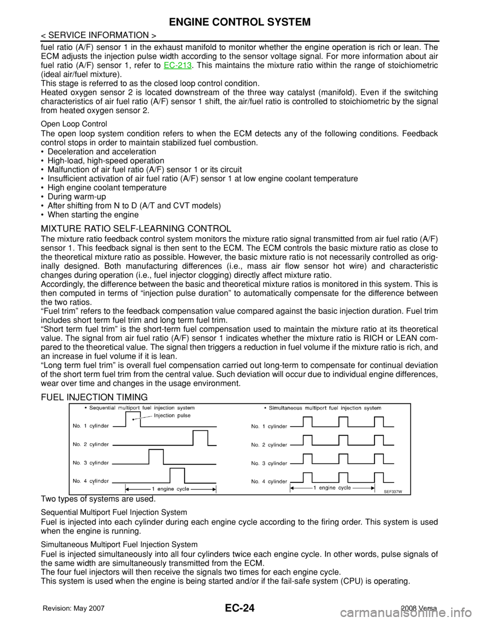
FUEL INJECTION TIMING
Two types of systems are used.
Sequential Multiport Fuel Injection System
Fuel is injected into each cylinder during each engine cycle according to the firing order. This system is used
when the engine is running.
Simultaneous Multiport Fuel Injection System
Fuel is injected simultaneously into all four cylinders twice each engine cycle. In other words, pulse signals of
the same width are simultaneously transmitted from the ECM.
The four fuel injectors will then receive the signals two times for each engine cycle.
This system is used when the engine is being started and/or if the fail-safe system (CPU) is operating.
SEF337W
Page 1099 of 2771

ENGINE CONTROL SYSTEM
EC-25
< SERVICE INFORMATION >
C
D
E
F
G
H
I
J
K
L
MA
EC
N
P O
FUEL SHUT-OFF
Fuel to each cylinder is cut off during deceleration, operation of the engine at excessively high speeds or oper-
ation of the vehicle at excessively high speeds.
Electronic Ignition (EI) SystemINFOID:0000000001702556
INPUT/OUTPUT SIGNAL CHART
*1: This signal is sent to the ECM through CAN communication line.
*2: ECM determines the start signal status by the signals of engine speed and battery voltage.
SYSTEM DESCRIPTION
Firing order: 1 - 3 - 4 - 2
The ignition timing is controlled by the ECM to maintain the best air-fuel ratio for every running condition of the
engine. The ignition timing data is stored in the ECM.
The ECM receives information such as the injection pulse width and camshaft position sensor (PHASE) sig-
nal. Computing this information, ignition signals are transmitted to the power transistor.
During the following conditions, the ignition timing is revised by the ECM according to the other data stored in
the ECM.
• At starting
• During warm-up
•At idle
• At low battery voltage
• During acceleration
The knock sensor retard system is designed only for emergencies. The basic ignition timing is programmed
within the anti-knocking zone, if recommended fuel is used under dry conditions. The retard system does not
operate under normal driving conditions. If engine knocking occurs, the knock sensor monitors the condition.
The signal is transmitted to the ECM. The ECM retards the ignition timing to eliminate the knocking condition.
Fuel Cut Control (at No Load and High Engine Speed)INFOID:0000000001702557
INPUT/OUTPUT SIGNAL CHART
*: This signal is sent to the ECM through CAN communication line.
SYSTEM DESCRIPTION
Sensor Input Signal to ECM ECM function Actuator
Crankshaft position sensor (POS)
Engine speed*
2
Piston position
Ignition timing
controlPower transistor Camshaft position sensor (PHASE)
Mass air flow sensor Amount of intake air
Engine coolant temperature sensor Engine coolant temperature
Throttle position sensor Throttle position
Accelerator pedal position sensor Accelerator pedal position
Battery
Battery voltage*
2
Knock sensor Engine knocking
Park/neutral position (PNP) switch Gear position
Wheel sensor
Vehicle speed*
1
Sensor Input Signal to ECM ECM function Actuator
Park/neutral position (PNP) switch Neutral position
Fuel cut control Fuel injector Accelerator pedal position sensor Accelerator pedal position
Engine coolant temperature sensor Engine coolant temperature
Crankshaft position sensor (POS)
Camshaft position sensor (PHASE)Engine speed
Wheel sensor Vehicle speed*
Page 1144 of 2771
EC-70
< SERVICE INFORMATION >
BASIC SERVICE PROCEDURE
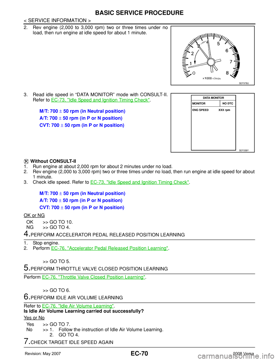
2. Rev engine (2,000 to 3,000 rpm) two or three times under no
load, then run engine at idle speed for about 1 minute.
3. Read idle speed in “DATA MONITOR” mode with CONSULT-II.
Refer to EC-73, "
Idle Speed and Ignition Timing Check".
Without CONSULT-II
1. Run engine at about 2,000 rpm for about 2 minutes under no load.
2. Rev engine (2,000 to 3,000 rpm) two or three times under no load, then run engine at idle speed for about
1 minute.
3. Check idle speed. Refer to EC-73, "
Idle Speed and Ignition Timing Check".
OK or NG
OK >> GO TO 10.
NG >> GO TO 4.
4.PERFORM ACCELERATOR PEDAL RELEASED POSITION LEARNING
1. Stop engine.
2. Perform EC-76, "
Accelerator Pedal Released Position Learning".
>> GO TO 5.
5.PERFORM THROTTLE VALVE CLOSED POSITION LEARNING
Perform EC-76, "
Throttle Valve Closed Position Learning".
>> GO TO 6.
6.PERFORM IDLE AIR VOLUME LEARNING
Refer to EC-76, "
Idle Air Volume Learning".
Is Idle Air Volume Learning carried out successfully?
Ye s o r N o
Ye s > > G O T O 7 .
No >> 1. Follow the instruction of Idle Air Volume Learning.
2. GO TO 4.
7.CHECK TARGET IDLE SPEED AGAIN
SEF978U
M/T: 700 ± 50 rpm (in Neutral position)
A/T: 700 ± 50 rpm (in P or N position)
CVT: 700 ± 50 rpm (in P or N position)
SEF058Y
M/T: 700 ± 50 rpm (in Neutral position)
A/T: 700 ± 50 rpm (in P or N position)
CVT: 700 ± 50 rpm (in P or N position)
Page 1145 of 2771
BASIC SERVICE PROCEDURE
EC-71
< SERVICE INFORMATION >
C
D
E
F
G
H
I
J
K
L
MA
EC
N
P O
With CONSULT-II
1. Start engine and warm it up to normal operating temperature.
2. Read idle speed in “DATA MONITOR” mode with CONSULT-II.
Refer to EC-73, "
Idle Speed and Ignition Timing Check".
Without CONSULT-II
1. Start engine and warm it up to normal operating temperature.
2. Check idle speed. Refer to EC-73, "
Idle Speed and Ignition Tim-
ing Check".
OK or NG
OK >> GO TO 10.
NG >> GO TO 8.
8.DETECT MALFUNCTIONING PART
Check the following.
• Check crankshaft position sensor (POS) and circuit.
Refer to EC-295
.
• Check camshaft position sensor (PHASE) and circuit.
Refer to EC-302
.
OK or NG
OK >> GO TO 9.
NG >> 1. Repair or replace.
2. GO TO 4.
9.CHECK ECM FUNCTION
1. Substitute another known-good ECM to check ECM function. (ECM may be the cause of an incident, but
this is a rare case.)
2. Perform initialization of NVIS (NATS) system and registration of all NVIS (NATS) ignition key IDs.
Refer to BL-211, "
ECM Re-communicating Function".
>> GO TO 4.
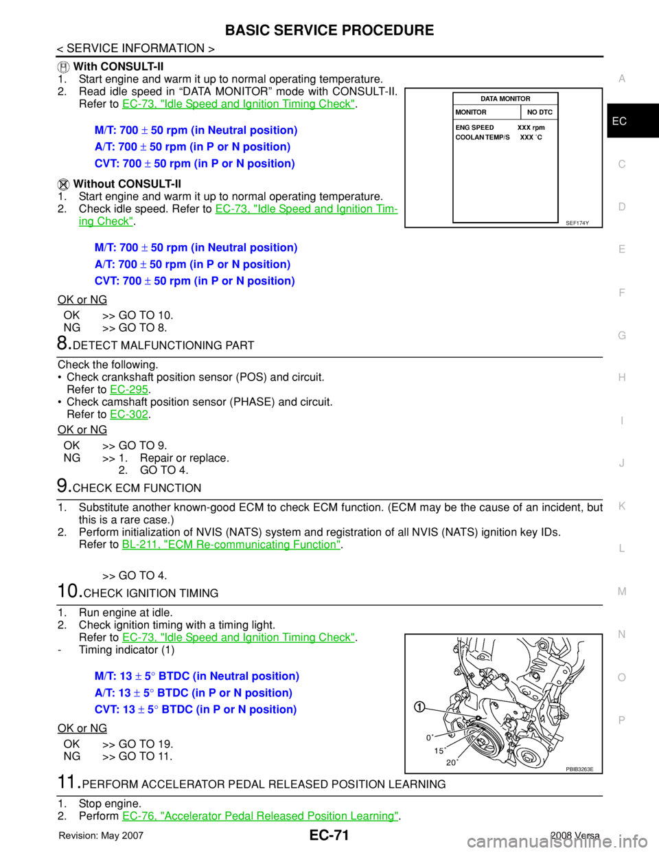
10.CHECK IGNITION TIMING
1. Run engine at idle.
2. Check ignition timing with a timing light.
Refer to EC-73, "
Idle Speed and Ignition Timing Check".
- Timing indicator (1)
OK or NG
OK >> GO TO 19.
NG >> GO TO 11.
11 .PERFORM ACCELERATOR PEDAL RELEASED POSITION LEARNING
1. Stop engine.
2. Perform EC-76, "
Accelerator Pedal Released Position Learning". M/T: 700 ± 50 rpm (in Neutral position)
A/T: 700 ± 50 rpm (in P or N position)
CVT: 700 ± 50 rpm (in P or N position)
M/T: 700 ± 50 rpm (in Neutral position)
A/T: 700 ± 50 rpm (in P or N position)
CVT: 700 ± 50 rpm (in P or N position)
SEF174Y
M/T: 13 ± 5° BTDC (in Neutral position)
A/T: 13 ± 5° BTDC (in P or N position)
CVT: 13 ± 5° BTDC (in P or N position)
PBIB3263E
Page 1146 of 2771
EC-72
< SERVICE INFORMATION >
BASIC SERVICE PROCEDURE
>> GO TO 12.
12.PERFORM THROTTLE VALVE CLOSED POSITION LEARNING
Perform EC-76, "
Throttle Valve Closed Position Learning".
>> GO TO 13.
13.PERFORM IDLE AIR VOLUME LEARNING
Refer to EC-76, "
Idle Air Volume Learning".
Is Idle Air Volume Learning carried out successfully?
Ye s o r N o
Yes >> GO TO 14.
No >> 1. Follow the instruction of Idle Air Volume Learning.
2. GO TO 4.
14.CHECK TARGET IDLE SPEED AGAIN
With CONSULT-II
1. Start engine and warm it up to normal operating temperature.
2. Read idle speed in “DATA MONITOR” mode with CONSULT-II.
Refer to EC-73, "
Idle Speed and Ignition Timing Check".
Without CONSULT-II
1. Start engine and warm it up to normal operating temperature.
2. Check idle speed. Refer to EC-73, "
Idle Speed and Ignition Tim-
ing Check".
OK or NG
OK >> GO TO 15.
NG >> GO TO 17.
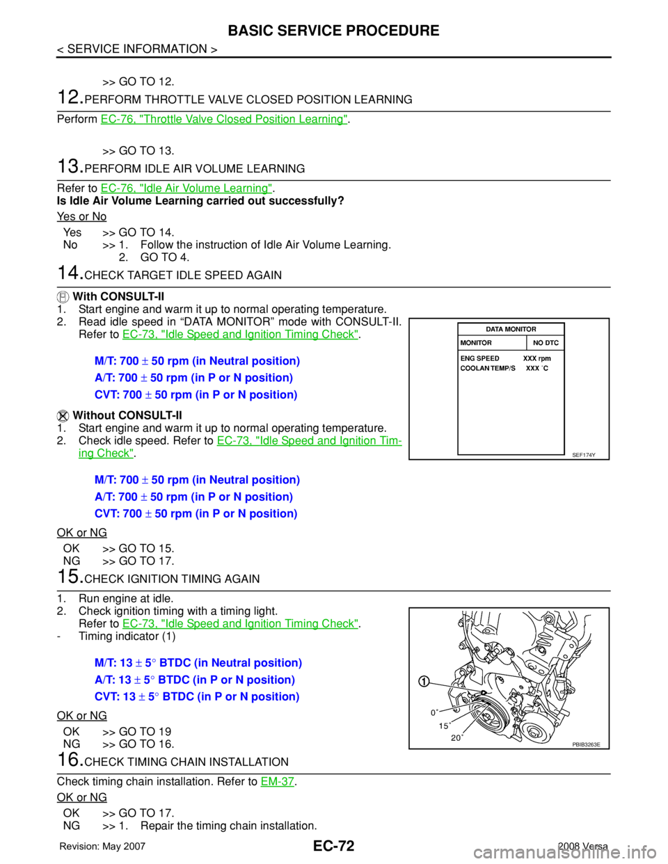
15.CHECK IGNITION TIMING AGAIN
1. Run engine at idle.
2. Check ignition timing with a timing light.
Refer to EC-73, "
Idle Speed and Ignition Timing Check".
- Timing indicator (1)
OK or NG
OK >> GO TO 19
NG >> GO TO 16.
16.CHECK TIMING CHAIN INSTALLATION
Check timing chain installation. Refer to EM-37
.
OK or NG
OK >> GO TO 17.
NG >> 1. Repair the timing chain installation.M/T: 700 ± 50 rpm (in Neutral position)
A/T: 700 ± 50 rpm (in P or N position)
CVT: 700 ± 50 rpm (in P or N position)
M/T: 700 ± 50 rpm (in Neutral position)
A/T: 700 ± 50 rpm (in P or N position)
CVT: 700 ± 50 rpm (in P or N position)
SEF174Y
M/T: 13 ± 5° BTDC (in Neutral position)
A/T: 13 ± 5° BTDC (in P or N position)
CVT: 13 ± 5° BTDC (in P or N position)
PBIB3263E
Page 1149 of 2771
BASIC SERVICE PROCEDURE
EC-75
< SERVICE INFORMATION >
C
D
E
F
G
H
I
J
K
L
MA
EC
N
P O
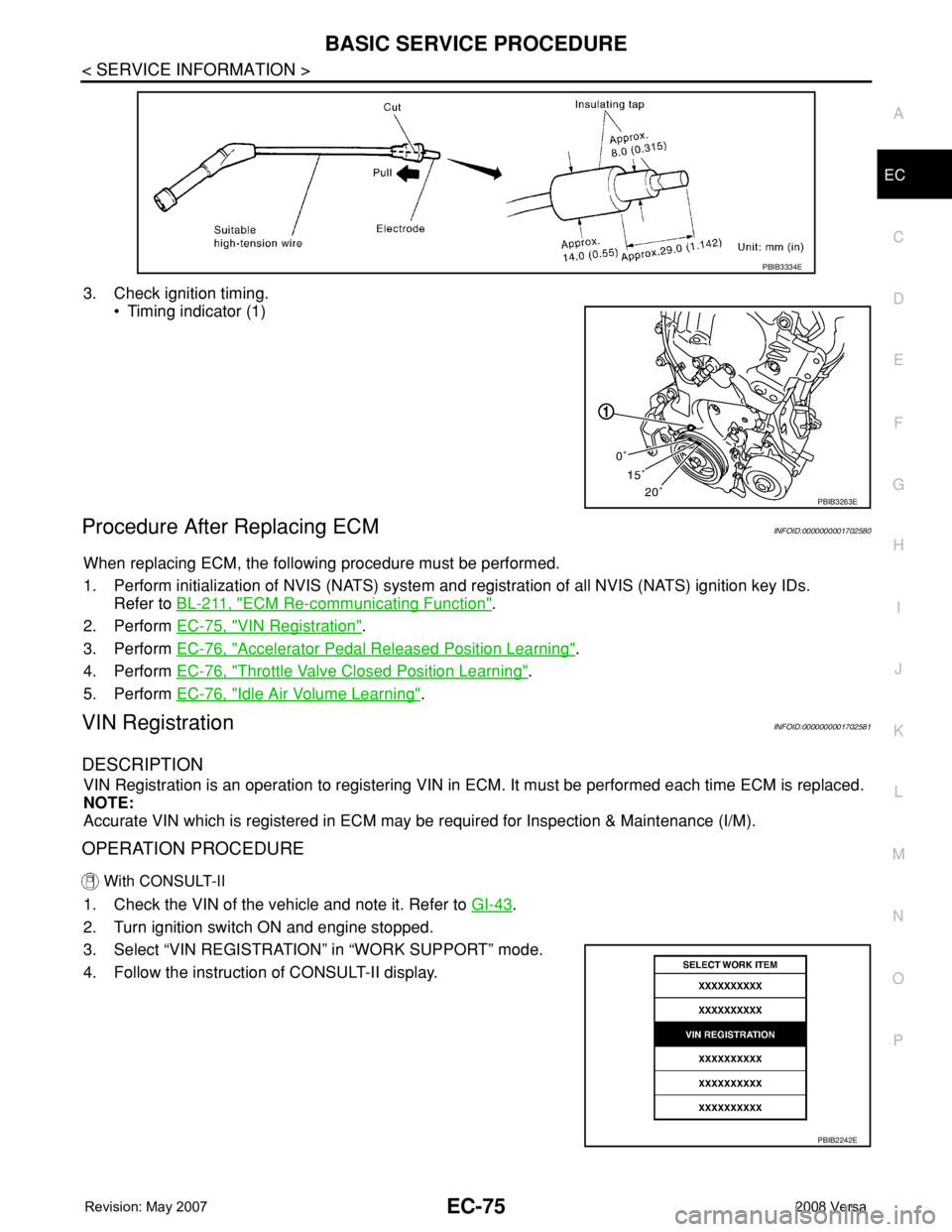
3. Check ignition timing.
• Timing indicator (1)
Procedure After Replacing ECMINFOID:0000000001702580
When replacing ECM, the following procedure must be performed.
1. Perform initialization of NVIS (NATS) system and registration of all NVIS (NATS) ignition key IDs.
Refer to BL-211, "
ECM Re-communicating Function".
2. Perform EC-75, "
VIN Registration".
3. Perform EC-76, "
Accelerator Pedal Released Position Learning".
4. Perform EC-76, "
Throttle Valve Closed Position Learning".
5. Perform EC-76, "
Idle Air Volume Learning".
VIN RegistrationINFOID:0000000001702581
DESCRIPTION
VIN Registration is an operation to registering VIN in ECM. It must be performed each time ECM is replaced.
NOTE:
Accurate VIN which is registered in ECM may be required for Inspection & Maintenance (I/M).
OPERATION PROCEDURE
With CONSULT-II
1. Check the VIN of the vehicle and note it. Refer to GI-43.
2. Turn ignition switch ON and engine stopped.
3. Select “VIN REGISTRATION” in “WORK SUPPORT” mode.
4. Follow the instruction of CONSULT-II display.
PBIB3334E
PBIB3263E
PBIB2242E
Page 1150 of 2771

EC-76
< SERVICE INFORMATION >
BASIC SERVICE PROCEDURE
Accelerator Pedal Released Position Learning
INFOID:0000000001702582
DESCRIPTION
Accelerator Pedal Released Position Learning is an operation to learn the fully released position of the accel-
erator pedal by monitoring the accelerator pedal position sensor output signal. It must be performed each time
harness connector of accelerator pedal position sensor or ECM is disconnected.
OPERATION PROCEDURE
1. Make sure that accelerator pedal is fully released.
2. Turn ignition switch ON and wait at least 2 seconds.
3. Turn ignition switch OFF and wait at least 10 seconds.
4. Turn ignition switch ON and wait at least 2 seconds.
5. Turn ignition switch OFF and wait at least 10 seconds.
Throttle Valve Closed Position LearningINFOID:0000000001702583
DESCRIPTION
Throttle Valve Closed Position Learning is an operation to learn the fully closed position of the throttle valve by
monitoring the throttle position sensor output signal. It must be performed each time harness connector of
electric throttle control actuator or ECM is disconnected.
OPERATION PROCEDURE
1. Make sure that accelerator pedal is fully released.
2. Turn ignition switch ON.
3. Turn ignition switch OFF and wait at least 10 seconds.
Make sure that throttle valve moves during above 10 seconds by confirming the operating sound.
Idle Air Volume LearningINFOID:0000000001702584
DESCRIPTION
Idle Air Volume Learning is an operation to learn the idle air volume that keeps each engine within the specific
range. It must be performed under any of the following conditions:
• Each time electric throttle control actuator or ECM is replaced.
• Idle speed or ignition timing is out of specification.
PREPARATION
Before performing Idle Air Volume Learning, make sure that all of the following conditions are satisfied.
Learning will be cancelled if any of the following conditions are missed for even a moment.
• Battery voltage: More than 12.9V (At idle)
• Engine coolant temperature: 70 - 95°C (158 - 203°F)
• Park/neutral position (PNP) switch: ON
• Electric load switch: OFF
[Air conditioner, headlamp, rear window defogger]
On vehicles equipped with daytime light systems, if the parking brake is applied before the engine is
started the headlamp will not be illuminated.
• Steering wheel: Neutral (Straight-ahead position)
• Vehicle speed: Stopped
• Transmission: Warmed-up
- Models with CONSULT-II (A/T and CVT models)
• Drive vehicle until “FLUID TEMP SE” in “DATA MONITOR” mode of “A/T” or “CVT” system indicates less
than 0.9V.
- Models without CONSULT-II (A/T and CVT models) and M/T models
• Drive vehicle for 10 minutes.
OPERATION PROCEDURE
With CONSULT-II
1. Perform EC-76, "Accelerator Pedal Released Position Learning".
2. Perform EC-76, "
Throttle Valve Closed Position Learning".