2008 NISSAN TIIDA Crash sensor
[x] Cancel search: Crash sensorPage 450 of 2771
BL-16
< SERVICE INFORMATION >
HOOD
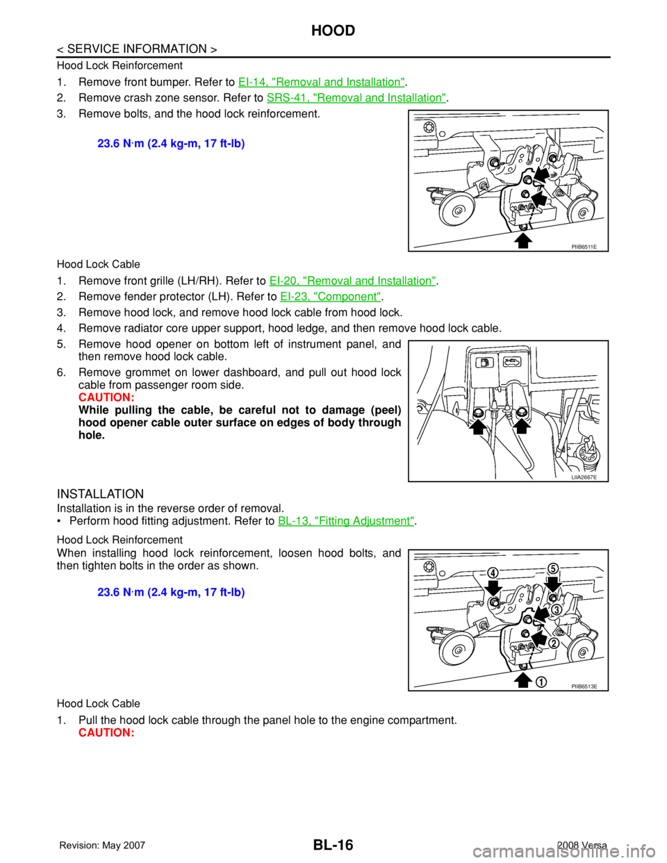
Hood Lock Reinforcement
1. Remove front bumper. Refer to EI-14, "Removal and Installation".
2. Remove crash zone sensor. Refer to SRS-41, "
Removal and Installation".
3. Remove bolts, and the hood lock reinforcement.
Hood Lock Cable
1. Remove front grille (LH/RH). Refer to EI-20, "Removal and Installation".
2. Remove fender protector (LH). Refer to EI-23, "
Component".
3. Remove hood lock, and remove hood lock cable from hood lock.
4. Remove radiator core upper support, hood ledge, and then remove hood lock cable.
5. Remove hood opener on bottom left of instrument panel, and
then remove hood lock cable.
6. Remove grommet on lower dashboard, and pull out hood lock
cable from passenger room side.
CAUTION:
While pulling the cable, be careful not to damage (peel)
hood opener cable outer surface on edges of body through
hole.
INSTALLATION
Installation is in the reverse order of removal.
• Perform hood fitting adjustment. Refer to BL-13, "
Fitting Adjustment".
Hood Lock Reinforcement
When installing hood lock reinforcement, loosen hood bolts, and
then tighten bolts in the order as shown.
Hood Lock Cable
1. Pull the hood lock cable through the panel hole to the engine compartment.
CAUTION: 23.6 N·m (2.4 kg-m, 17 ft-lb)
PIIB6511E
LIIA2667E
23.6 N·m (2.4 kg-m, 17 ft-lb)
PIIB6513E
Page 2474 of 2771

HARNESS
PG-41
< SERVICE INFORMATION >
C
D
E
F
G
H
I
J
L
MA
B
PG
N
O
P
C3 E6 — : Fuse and fusible link box D3 E53 B/2: Front combination lamp LH
(parking)
B1 E7 SMJ : To M69
D3 E8 SMJ : To F8
B4 E9 BR/2 : Fusible link box (battery)
B3 E10 GR/2 : Fusible link box (battery)
B1 E11 B/2 : To M78
A3 E12 B/6 : Accelerator pedal position sensor
A2 E13 B/2 : Stop lamp switch (with M/T)
A2 E13 W/4 : Stop lamp switch (without M/T)
D3 E14 — : Engine ground (crash zone sensor)
C2 E15 — : Engine ground
B2 E16 B/32 : ECM
C5 E18 B/1 : Horn (low)
C4 E19 GR/6 : To F33
D5 E20 B/1 : Horn (low)
D3 E25 B/3: Front combination lamp LH
(headlamp)
E4 E27 B/2 : Front fog lamp LH
D4 E29 B/2: Front combination lamp LH
(turn signal)
B1 E31 W/24 : TCM
B1 E32 GR/24 : TCM
A2 E34 BR/2 : Clutch interlock switch (with M/T)
A2 E35 BR/2 : ASCD clutch switch
A2 E36 BR/2 : ASCD brake switch
B4 E40 GR/2 : Brake fluid level switch
D3 E42 B/2: IPDM E/R (Intelligent Power Distribu-
tion Module Engine Room)
C3 E43 W/16: IPDM E/R (Intelligent Power Distribu-
tion Module Engine Room)
C3 E44 W/6: IPDM E/R (Intelligent Power Distribu-
tion Module Engine Room)
D3 E45 BR/12: IPDM E/R (Intelligent Power Distribu-
tion Module Engine Room)
D3 E46 W/12: IPDM E/R (Intelligent Power Distribu-
tion Module Engine Room)
Page 2475 of 2771
PG-42
< SERVICE INFORMATION >
HARNESS
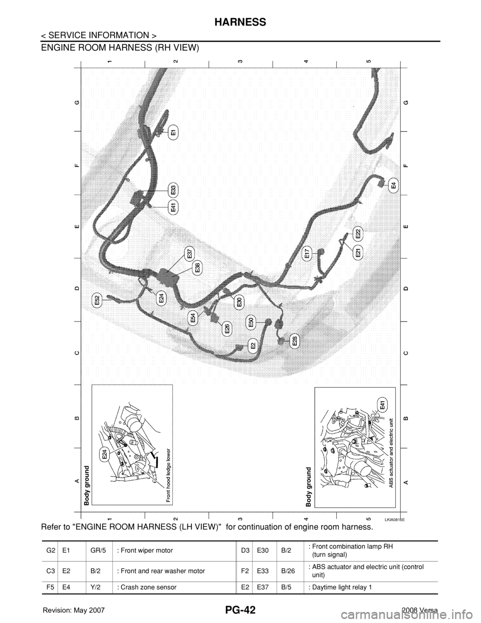
ENGINE ROOM HARNESS (RH VIEW)
Refer to "ENGINE ROOM HARNESS (LH VIEW)" for continuation of engine room harness.
LKIA0816E
G2 E1 GR/5 : Front wiper motor D3 E30 B/2: Front combination lamp RH
(turn signal)
C3 E2 B/2 : Front and rear washer motor F2 E33 B/26: ABS actuator and electric unit (control
unit)
F5 E4 Y/2 : Crash zone sensor E2 E37 B/5 : Daytime light relay 1
Page 2635 of 2771

SRS-1
RESTRAINTS
C
D
E
F
G
I
J
K
L
M
SECTION SRS
A
B
SRS
N
O
P
CONTENTS
SUPPLEMENTAL RESTRAINT SYSTEM (SRS)
PRECAUTION ...............................................2
PRECAUTIONS ...................................................2
Precaution for Supplemental Restraint System
(SRS) "AIR BAG" and "SEAT BELT PRE-TEN-
SIONER" ...................................................................
2
Precaution for SRS "AIR BAG" and "SEAT BELT
PRE-TENSIONER" Service ......................................
2
Occupant Classification System Precaution .............2
SYMPTOM DIAGNOSIS ...............................3
SUPPLEMENTAL RESTRAINT SYSTEM
(SRS) ...................................................................
3
SRS Configuration ....................................................3
Driver Air Bag Module ...............................................4
Front Passenger Air Bag Module ..............................4
Front Side Air Bag .....................................................4
Side Curtain Air Bag ..................................................4
Front Seat Belt Pre-tensioner with Load Limiter .......5
Occupant Classification System (OCS) ....................5
Direct-connect SRS Component Connectors ............6
TROUBLE DIAGNOSIS ......................................7
Trouble Diagnosis Introduction .................................7
SRS Component Parts Location ...............................9
Schematic ...............................................................10
Wiring Diagram - SRS- ............................................11
CONSULT-III Function (AIR BAG) ..........................16
Self-Diagnosis Function (Without CONSULT-III) ....17
SRS Operation Check .............................................18
Trouble Diagnosis with CONSULT-III .....................19
Trouble Diagnosis without CONSULT-III ................27
Trouble Diagnosis: "AIR BAG" Warning Lamp
Does Not Turn Off ...................................................
30
Trouble Diagnosis: "AIR BAG" Warning Lamp
Does Not Turn On ...................................................
31
ON-VEHICLE REPAIR .................................33
DRIVER AIR BAG MODULE ............................33
Removal and Installation .........................................33
SPIRAL CABLE ................................................36
Removal and Installation .........................................36
FRONT PASSENGER AIR BAG MODULE ......38
Removal and Installation .........................................38
SIDE CURTAIN AIR BAG MODULE ................39
Component ..............................................................39
Removal and Installation .........................................39
CRASH ZONE SENSOR ...................................41
Removal and Installation .........................................41
SIDE AIR BAG (SATELLITE) SENSOR ...........42
Removal and Installation .........................................42
FRONT SEAT BELT PRE-TENSIONER ...........43
Removal and Installation .........................................43
DIAGNOSIS SENSOR UNIT .............................44
Removal and Installation .........................................44
OCCUPANT CLASSIFICATION SYSTEM
CONTROL UNIT ................................................
45
Removal and Installation .........................................45
COLLISION DIAGNOSIS ..................................46
For Frontal Collision ................................................46
For Side and Rollover Collision ...............................47
Page 2643 of 2771
TROUBLE DIAGNOSIS
SRS-9
< SYMPTOM DIAGNOSIS >
C
D
E
F
G
I
J
K
L
MA
B
SRS
N
O
P
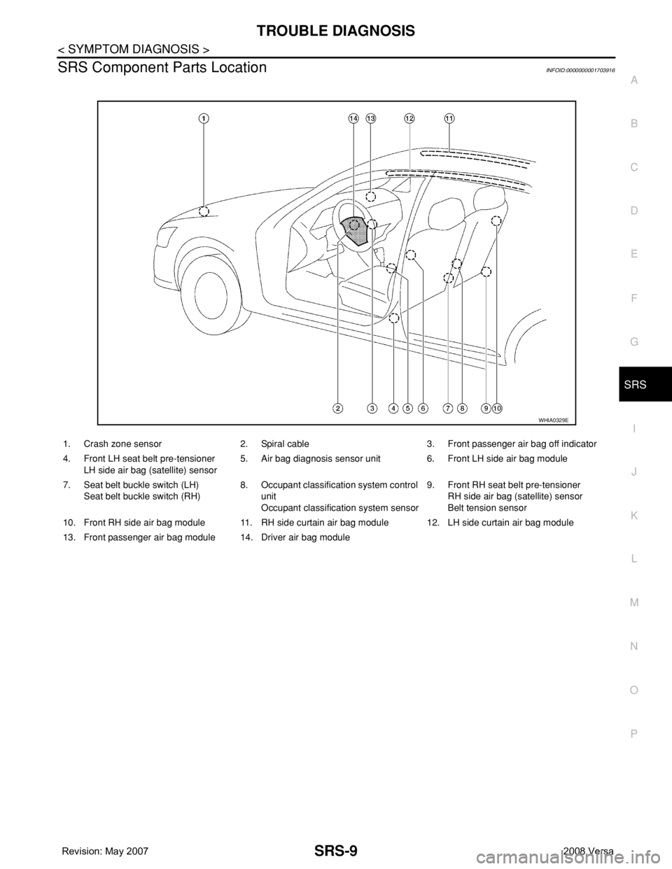
SRS Component Parts LocationINFOID:0000000001703916
1. Crash zone sensor 2. Spiral cable 3. Front passenger air bag off indicator
4. Front LH seat belt pre-tensioner
LH side air bag (satellite) sensor5. Air bag diagnosis sensor unit 6. Front LH side air bag module
7. Seat belt buckle switch (LH)
Seat belt buckle switch (RH)8. Occupant classification system control
unit
Occupant classification system sensor9. Front RH seat belt pre-tensioner
RH side air bag (satellite) sensor
Belt tension sensor
10. Front RH side air bag module 11. RH side curtain air bag module 12. LH side curtain air bag module
13. Front passenger air bag module 14. Driver air bag module
WHIA0329E
Page 2654 of 2771
![NISSAN TIIDA 2008 Service Repair Manual SRS-20
< SYMPTOM DIAGNOSIS >
TROUBLE DIAGNOSIS
CONSULT-III Diagnostic Code Chart ("SELF-DIAG [CURRENT]")
Diagnostic item ExplanationRepair order
Recheck SRS at each replacement
NO DTC IS DETEC](/manual-img/5/57399/w960_57399-2653.png "NISSAN TIIDA 2008 Service Repair Manual SRS-20
< SYMPTOM DIAGNOSIS >
TROUBLE DIAGNOSIS
CONSULT-III Diagnostic Code Chart (\"SELF-DIAG [CURRENT]\")
Diagnostic item ExplanationRepair order
Recheck SRS at each replacement
NO DTC IS DETEC")
SRS-20
< SYMPTOM DIAGNOSIS >
TROUBLE DIAGNOSIS
CONSULT-III Diagnostic Code Chart ("SELF-DIAG [CURRENT]")
Diagnostic item ExplanationRepair order
Recheck SRS at each replacement
NO DTC IS DETECTEDMalfunction is indicat-
ed by the “AIR BAG”
warning lamp in User
mode.Low battery voltage (Less than 9V) 1. Go to SC-4
2. Go to "DIAGNOSTIC PROCE-
DURE 3" .
“SELF-DIAG [PAST]” memory might
not be erased.Go to "DIAGNOSTIC PROCEDURE 4"
.
Intermittent malfunction has been
detected in the past.Go to "DIAGNOSTIC PROCEDURE 5"
.
No malfunction is detected in User mode. —
DRIVER AIRBAG MODULE
[OPEN]
[B1049] or [B1054]Driver air bag module circuit is open (including the spiral ca-
ble).1. Visually check the wiring harness
connection.
2. Replace the harness if it has visi-
ble damage.
3. Replace driver air bag module.
4. Replace the spiral cable.
5. Replace the air bag diagnosis
sensor unit.
6. Replace the related harness. DRIVER AIRBAG MODULE
[VB-SHORT]
[B1050] or [B1055]Driver air bag module circuit is shorted to some power supply
circuit (including the spiral cable).
DRIVER AIRBAG MODULE
[GND-SHORT]
[B1051] or [B1056]Driver air bag module circuit is shorted to ground (including
the spiral cable).
DRIVER AIRBAG MODULE
[SHORT]
[B1052] or [B1057]Driver air bag module circuits are shorted to each other.
ASSIST A/B MODULE
[OPEN]
[B1065] or [B1070]Front passenger air bag module circuit is open. 1. Visually check the wiring harness
connection.
2. Replace the harness if it has visi-
ble damage.
3. Replace front passenger air bag
module.
4. Replace the air bag diagnosis
sensor unit.
5. Replace the related harness. ASSIST A/B MODULE
[VB-SHORT]
[B1066] or [B1071]Front passenger air bag module circuit is shorted to some
power supply circuit.
ASSIST A/B MODULE
[GND-SHORT]
[B1067] or [B1072]Front passenger air bag module circuit is shorted to ground.
ASSIST A/B MODULE
[SHORT]
[B1068] or [B1073]Front passenger air bag module circuits are shorted to each
other.
CRASH ZONE SEN
[UNIT FAIL]
[B1033] or [B1034]
CRASH ZONE SEN
[COMM FAIL]
[B1035]Crash zone sensor 1. Visually check the wiring harness
connection.
2. Replace the harness if it has visi-
ble damage.
3. Replace the crash zone sensor.
4. Replace the air bag diagnosis
sensor unit.
5. Replace the related harness.
SIDE MODULE LH
[OPEN]
[B1134]Front LH side air bag module circuit is open. 1. Visually check the wiring harness
connection.
2. Replace the harness if it has visi-
ble damage.
3. Replace front LH seat back as-
sembly (front LH side air bag
module).
4. Replace the air bag diagnosis
sensor unit.
5. Replace the related harness. SIDE MODULE LH
[VB-SHORT]
[B1135]Front LH side air bag module circuit is shorted to some power
supply circuit.
SIDE MODULE LH
[GND-SHORT]
[B1136]Front LH side air bag module circuit is shorted to ground.
SIDE MODULE LH
[SHORT]
[B1137]Front LH side air bag module circuits are shorted to each oth-
er.
Page 2659 of 2771
![NISSAN TIIDA 2008 Service Repair Manual TROUBLE DIAGNOSIS
SRS-25
< SYMPTOM DIAGNOSIS >
C
D
E
F
G
I
J
K
L
MA
B
SRS
N
O
P
CRASH ZONE SEN
[UNIT FAIL]
[B1033] or [B1034]
CRASH ZONE SEN
[COMM FAIL]
[B1035]Crash zone sensor 1. Visually check the](/manual-img/5/57399/w960_57399-2658.png "NISSAN TIIDA 2008 Service Repair Manual TROUBLE DIAGNOSIS
SRS-25
< SYMPTOM DIAGNOSIS >
C
D
E
F
G
I
J
K
L
MA
B
SRS
N
O
P
CRASH ZONE SEN
[UNIT FAIL]
[B1033] or [B1034]
CRASH ZONE SEN
[COMM FAIL]
[B1035]Crash zone sensor 1. Visually check the")
TROUBLE DIAGNOSIS
SRS-25
< SYMPTOM DIAGNOSIS >
C
D
E
F
G
I
J
K
L
MA
B
SRS
N
O
P
CRASH ZONE SEN
[UNIT FAIL]
[B1033] or [B1034]
CRASH ZONE SEN
[COMM FAIL]
[B1035]Crash zone sensor 1. Visually check the wiring harness
connection.
2. Replace the harness if it has visi-
ble damage.
3. Replace the crash zone sensor.
4. Replace the air bag diagnosis
sensor unit.
5. Replace the related harness.
SIDE MODULE LH
[OPEN]
[B1134]Front LH side air bag module circuit is open. 1. Visually check the wiring harness
connection.
2. Replace the harness if it has visi-
ble damage.
3. Replace front LH seat back as-
sembly (front LH side air bag
module).
4. Replace the air bag diagnosis
sensor unit.
5. Replace the related harness. SIDE MODULE LH
[VB-SHORT]
[B1135]Front LH side air bag module circuit is shorted to some power
supply circuit.
SIDE MODULE LH
[GND-SHORT]
[B1136]Front LH side air bag module circuit is shorted to ground.
SIDE MODULE LH
[SHORT]
[B1137]Front LH side air bag module circuits are shorted to each oth-
er.
SIDE MODULE RH
[OPEN]
[B1129]Front RH side air bag module circuit is open. 1. Visually check the wiring harness
connection.
2. Replace the harness if it has visi-
ble damage.
3. Replace front RH seat back as-
sembly (front RH side air bag
module).
4. Replace the air bag diagnosis
sensor unit.
5. Replace the related harness. SIDE MODULE RH
[VB-SHORT]
[B1130]Front RH side air bag module circuit is shorted to some power
supply circuit.
SIDE MODULE RH
[GND-SHORT]
[B1131]Front RH side air bag module circuit is shorted to ground.
SIDE MODULE RH
[SHORT]
[B1132]Front RH side air bag module circuits are shorted to each oth-
er.
SATELLITE SENS LH
[UNIT FAIL]
[ B 111 8 ] o r [ B 111 9 ]
SATELLITE SENS LH
[COMM FAIL]
[B1120]LH side air bag (satellite) sensor 1. Visually check the wiring harness
connection.
2. Replace the harness if it has visi-
ble damage.
3. Replace the LH side air bag (sat-
ellite) sensor.
4. Replace the air bag diagnosis
sensor unit.
5. Replace the related harness.
SATELLITE SENS RH
[UNIT FAIL]
[ B 111 3 ] o r [ B 111 4 ]
SATELLITE SENS RH
[COMM FAIL]
[ B 111 5 ]RH side air bag (satellite) sensor 1. Visually check the wiring harness
connection.
2. Replace the harness if it has visi-
ble damage.
3. Replace the RH side air bag (sat-
ellite) sensor.
4. Replace the air bag diagnosis
sensor unit.
5. Replace the related harness. Diagnostic item ExplanationRepair order
Recheck SRS at each replacement
Page 2675 of 2771
CRASH ZONE SENSOR
SRS-41
< ON-VEHICLE REPAIR >
C
D
E
F
G
I
J
K
L
MA
B
SRS
N
O
P
CRASH ZONE SENSOR
Removal and InstallationINFOID:0000000001703931
REMOVAL
CAUTION:
• Before servicing the SRS, turn ignition switch OFF, disconnect both battery cables and wait at least
3 minutes.
• Do not disassemble the crash zone sensor.
• Do not use old nuts after removal; replace with new nuts.
• Replace the crash zone sensor if it has been dropped or sus-
tained an impact.
• Check crash zone sensor to make sure it is free of deformi-
ties, dents, cracks or rust. If it shows any visible signs of dam-
age, replace it with a new one.
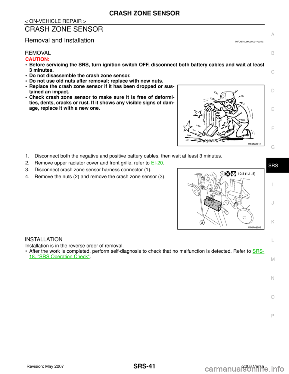
1. Disconnect both the negative and positive battery cables, then wait at least 3 minutes.
2. Remove upper radiator cover and front grille, refer to EI-20
.
3. Disconnect crash zone sensor harness connector (1).
4. Remove the nuts (2) and remove the crash zone sensor (3).
INSTALLATION
Installation is in the reverse order of removal.
• After the work is completed, perform self-diagnosis to check that no malfunction is detected. Refer to SRS-
18, "SRS Operation Check".
WHIA0321E
WHIA0320E