2008 NISSAN TIIDA Engine timing
[x] Cancel search: Engine timingPage 1221 of 2771
DTC P0011 IVT CONTROL
EC-147
< SERVICE INFORMATION >
C
D
E
F
G
H
I
J
K
L
MA
EC
N
P O
DTC P0011 IVT CONTROL
DescriptionINFOID:0000000001702617
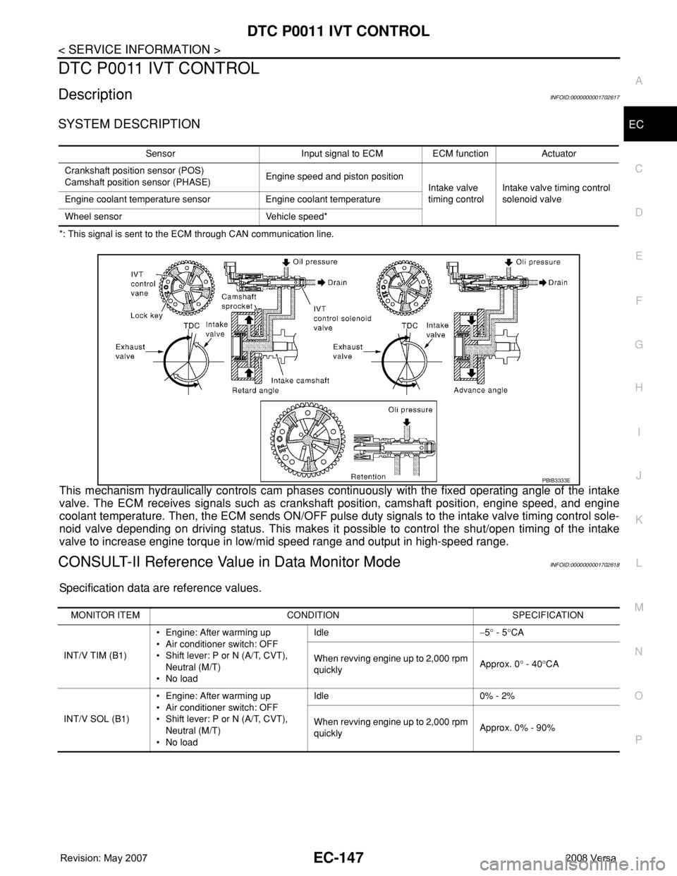
SYSTEM DESCRIPTION
*: This signal is sent to the ECM through CAN communication line.
This mechanism hydraulically controls cam phases continuously with the fixed operating angle of the intake
valve. The ECM receives signals such as crankshaft position, camshaft position, engine speed, and engine
coolant temperature. Then, the ECM sends ON/OFF pulse duty signals to the intake valve timing control sole-
noid valve depending on driving status. This makes it possible to control the shut/open timing of the intake
valve to increase engine torque in low/mid speed range and output in high-speed range.
CONSULT-II Reference Value in Data Monitor ModeINFOID:0000000001702618
Specification data are reference values.
Sensor Input signal to ECM ECM function Actuator
Crankshaft position sensor (POS)
Camshaft position sensor (PHASE)Engine speed and piston position
Intake valve
timing controlIntake valve timing control
solenoid valve Engine coolant temperature sensor Engine coolant temperature
Wheel sensor Vehicle speed*
PBIB3333E
MONITOR ITEM CONDITION SPECIFICATION
INT/V TIM (B1)• Engine: After warming up
• Air conditioner switch: OFF
• Shift lever: P or N (A/T, CVT),
Neutral (M/T)
•No loadIdle−5° - 5°CA
When revving engine up to 2,000 rpm
quicklyApprox. 0° - 40°CA
INT/V SOL (B1)• Engine: After warming up
• Air conditioner switch: OFF
• Shift lever: P or N (A/T, CVT),
Neutral (M/T)
•No loadIdle 0% - 2%
When revving engine up to 2,000 rpm
quicklyApprox. 0% - 90%
Page 1222 of 2771
EC-148
< SERVICE INFORMATION >
DTC P0011 IVT CONTROL
On Board Diagnosis Logic
INFOID:0000000001702619
FAIL-SAFE MODE
ECM enters in fail-safe mode when the malfunction is detected.
DTC Confirmation ProcedureINFOID:0000000001702620
CAUTION:
Always drive at a safe speed.
NOTE:
•If DTC P0011 is displayed with DTC P0075, first perform trouble diagnosis for DTC P0075.
See EC-162
.
• If DTC Confirmation Procedure has been previously conducted, always turn ignition switch OFF and wait at
least 10 seconds before conducting the next test.
TESTING CONDITION:
Before performing the following procedure, confirm that battery voltage is between 10V and 16V at
idle.
WITH CONSULT-II
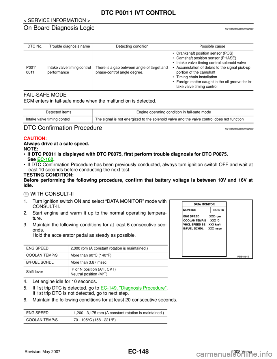
1. Turn ignition switch ON and select “DATA MONITOR” mode with
CONSULT-II.
2. Start engine and warm it up to the normal operating tempera-
ture.
3. Maintain the following conditions for at least 6 consecutive sec-
onds.
Hold the accelerator pedal as steady as possible.
4. Let engine idle for 10 seconds.
5. If 1st trip DTC is detected, go to EC-149, "
Diagnosis Procedure".
If 1st trip DTC is not detected, go to next step.
6. Maintain the following conditions for at least 20 consecutive seconds.
DTC No. Trouble diagnosis name Detecting condition Possible cause
P0011
0011Intake valve timing control
performanceThere is a gap between angle of target and
phase-control angle degree.• Crankshaft position sensor (POS)
• Camshaft position sensor (PHASE)
• Intake valve timing control solenoid valve
• Accumulation of debris to the signal pick-up
portion of the camshaft
• Timing chain installation
• Foreign matter caught in the oil groove for in-
take valve timing control
Detected items Engine operating condition in fail-safe mode
Intake valve timing control The signal is not energized to the solenoid valve and the valve control does not function
ENG SPEED 2,000 rpm (A constant rotation is maintained.)
COOLAN TEMP/S More than 60°C (140°F)
B/FUEL SCHDL More than 3.87 msec
Shift lever P or N position (A/T, CVT)
Neutral position (M/T)
ENG SPEED 1,200 - 3,175 rpm (A constant rotation is maintained.)
COOLAN TEMP/S 70 - 105°C (158 - 221°F)
PBIB0164E
Page 1223 of 2771
DTC P0011 IVT CONTROL
EC-149
< SERVICE INFORMATION >
C
D
E
F
G
H
I
J
K
L
MA
EC
N
P O7. If 1st trip DTC is detected, go to EC-149, "Diagnosis Procedure".
WITH GST
Follow the procedure “WITH CONSULT-II” above.
Diagnosis ProcedureINFOID:0000000001702621
1.CHECK OIL PRESSURE WARNING LAMP
1. Start engine.
2. Check oil pressure warning lamp and confirm it is not illumi-
nated.
OK or NG
OK >> GO TO 2.
NG >> Go to LU-6, "
Inspection".
2.CHECK INTAKE VALVE TIMING CONTROL SOLENOID VALVE
Refer to EC-150, "
Component Inspection".
OK or NG
OK >> GO TO 3.
NG >> Replace intake valve timing control solenoid valve.
3.CHECK CRANKSHAFT POSITION SENSOR (POS)
Refer to EC-301, "
Component Inspection".
OK or NG
OK >> GO TO 4.
NG >> Replace crankshaft position sensor (POS).
4.CHECK CAMSHAFT POSITION SENSOR (PHASE)
Refer to EC-307, "
Component Inspection".
OK or NG
OK >> GO TO 5.
NG >> Replace camshaft position sensor (PHASE).
5.CHECK CAMSHAFT (INTAKE)
Check the following.
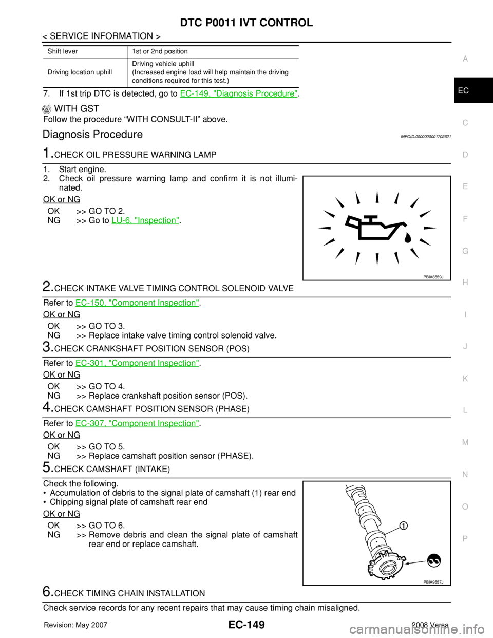
• Accumulation of debris to the signal plate of camshaft (1) rear end
• Chipping signal plate of camshaft rear end
OK or NG
OK >> GO TO 6.
NG >> Remove debris and clean the signal plate of camshaft
rear end or replace camshaft.
6.CHECK TIMING CHAIN INSTALLATION
Check service records for any recent repairs that may cause timing chain misaligned.
Shift lever 1st or 2nd position
Driving location uphillDriving vehicle uphill
(Increased engine load will help maintain the driving
conditions required for this test.)
PBIA8559J
PBIA9557J
Page 1236 of 2771
EC-162
< SERVICE INFORMATION >
DTC P0075 IVT CONTROL SOLENOID VALVE
DTC P0075 IVT CONTROL SOLENOID VALVE
Component DescriptionINFOID:0000000001702640
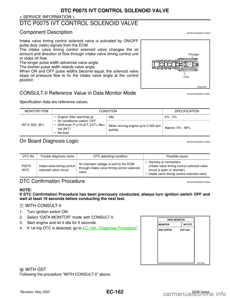
Intake valve timing control solenoid valve is activated by ON/OFF
pulse duty (ratio) signals from the ECM.
The intake valve timing control solenoid valve changes the oil
amount and direction of flow through intake valve timing control unit
or stops oil flow.
The longer pulse width advances valve angle.
The shorter pulse width retards valve angle.
When ON and OFF pulse widths become equal, the solenoid valve
stops oil pressure flow to fix the intake valve angle at the control
position.
CONSULT-II Reference Value in Data Monitor ModeINFOID:0000000001702641
Specification data are reference values.
On Board Diagnosis LogicINFOID:0000000001702642
DTC Confirmation ProcedureINFOID:0000000001702643
NOTE:
If DTC Confirmation Procedure has been previously conducted, always turn ignition switch OFF and
wait at least 10 seconds before conducting the next test.
WITH CONSULT-II
1. Turn ignition switch ON.
2. Select “DATA MONITOR” mode with CONSULT-II.
3. Start engine and let it idle for 5 seconds.
4. If 1st trip DTC is detected, go to EC-164, "
Diagnosis Procedure".
WITH GST
Following the procedure “WITH CONSULT-II” above.
PBIB1842E
MONITOR ITEM CONDITION SPECIFICATION
INT/V SOL (B1)• Engine: After warming up
• Air conditioner switch: OFF
• Shift lever: P or N (A/T, CVT), Neu-
tral (M/T)
•No loadIdle 0% - 2%
When revving engine up to 2,000 rpm
quicklyApprox. 0% - 90%
DTC No. Trouble diagnosis name DTC detecting condition Possible cause
P0075
0075Intake valve timing control
solenoid valve circuitAn improper voltage is sent to the ECM
through intake valve timing control solenoid
valve.• Harness or connectors
(Intake valve timing control solenoid valve
circuit is open or shorted.)
• Intake valve timing control solenoid valve
SEF058Y
Page 1238 of 2771
EC-164
< SERVICE INFORMATION >
DTC P0075 IVT CONTROL SOLENOID VALVE
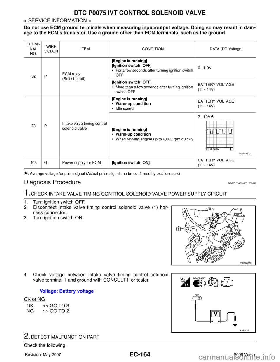
Do not use ECM ground terminals when measuring input/output voltage. Doing so may result in dam-
age to the ECM's transistor. Use a ground other than ECM terminals, such as the ground.
: Average voltage for pulse signal (Actual pulse signal can be confirmed by oscilloscope.)
Diagnosis ProcedureINFOID:0000000001702645
1.CHECK INTAKE VALVE TIMING CONTROL SOLENOID VALVE POWER SUPPLY CIRCUIT
1. Turn ignition switch OFF.
2. Disconnect intake valve timing control solenoid valve (1) har-
ness connector.
3. Turn ignition switch ON.
4. Check voltage between intake valve timing control solenoid
valve terminal 1 and ground with CONSULT-II or tester.
OK or NG
OK >> GO TO 3.
NG >> GO TO 2.
2.DETECT MALFUNCTION PART
Check the following.
TERMI-
NAL
NO.WIRE
COLORITEM CONDITION DATA (DC Voltage)
32 PECM relay
(Self shut-off)[Engine is running]
[Ignition switch: OFF]
• For a few seconds after turning ignition switch
OFF0 - 1.0V
[Ignition switch: OFF]
• More than a few seconds after turning ignition
switch OFFBATTERY VOLTAGE
(11 - 14V)
73 PIntake valve timing control
solenoid valve[Engine is running]
•Warm-up condition
• Idle speedBATTERY VOLTAGE
(11 - 14V)
[Engine is running]
•Warm-up condition
• When revving engine up to 2,000 rpm quickly7 - 10V
105 G Power supply for ECM[Ignition switch: ON]BATTERY VOLTAGE
(11 - 14V)
PBIA4937J
PBIB3323E
Voltage: Battery voltage
SEF212S
Page 1376 of 2771
EC-302
< SERVICE INFORMATION >
DTC P0340 CMP SENSOR (PHASE)
DTC P0340 CMP SENSOR (PHASE)
Component DescriptionINFOID:0000000001702808
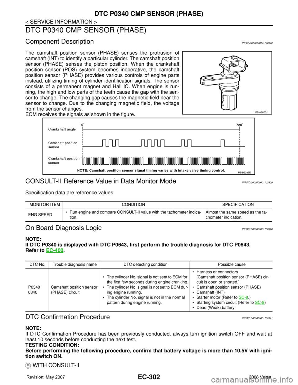
The camshaft position sensor (PHASE) senses the protrusion of
camshaft (INT) to identify a particular cylinder. The camshaft position
sensor (PHASE) senses the piston position. When the crankshaft
position sensor (POS) system becomes inoperative, the camshaft
position sensor (PHASE) provides various controls of engine parts
instead, utilizing timing of cylinder identification signals. The sensor
consists of a permanent magnet and Hall IC. When engine is run-
ning, the high and low parts of the teeth cause the gap with the sen-
sor to change. The changing gap causes the magnetic field near the
sensor to change. Due to the changing magnetic field, the voltage
from the sensor changes.
ECM receives the signals as shown in the figure.
CONSULT-II Reference Value in Data Monitor ModeINFOID:0000000001702809
Specification data are reference values.
On Board Diagnosis LogicINFOID:0000000001702810
NOTE:
If DTC P0340 is displayed with DTC P0643, first perform the trouble diagnosis for DTC P0643.
Refer to EC-400
.
DTC Confirmation ProcedureINFOID:0000000001702811
NOTE:
If DTC Confirmation Procedure has been previously conducted, always turn ignition switch OFF and wait at
least 10 seconds before conducting the next test.
TESTING CONDITION:
Before performing the following procedure, confirm that battery voltage is more than 10.5V with igni-
tion switch ON.
WITH CONSULT-II
PBIA9875J
PBIB2382E
MONITOR ITEM CONDITION SPECIFICATION
ENG SPEED• Run engine and compare CONSULT-II value with the tachometer indica-
tion.Almost the same speed as the ta-
chometer indication.
DTC No. Trouble diagnosis name DTC detecting condition Possible cause
P0340
0340Camshaft position sensor
(PHASE) circuit• The cylinder No. signal is not sent to ECM for
the first few seconds during engine cranking.
• The cylinder No. signal is not set to ECM dur-
ing engine running.
• The cylinder No. signal is not in the normal
pattern during engine running.• Harness or connectors
[Camshaft position sensor (PHASE) cir-
cuit is open or shorted.]
• Camshaft position sensor (PHASE)
• Camshaft (INT)
• Starter motor (Refer to SC-8
.)
• Starting system circuit (Refer to SC-8
)
• Dead (Weak) battery
Page 1382 of 2771

EC-308
< SERVICE INFORMATION >
DTC P0420 THREE WAY CATALYST FUNCTION
DTC P0420 THREE WAY CATALYST FUNCTION
On Board Diagnosis LogicINFOID:0000000001702816
The ECM monitors the switching frequency ratio of air fuel ratio (A/F)
sensor 1 and heated oxygen sensor 2.
A three way catalyst (manifold) with high oxygen storage capacity
will indicate a low switching frequency of heated oxygen sensor 2.
As oxygen storage capacity decreases, the heated oxygen sensor 2
switching frequency will increase.
When the frequency ratio of air fuel ratio (A/F) sensor 1 and heated
oxygen sensor 2 approaches a specified limit value, the three way
catalyst (manifold) malfunction is diagnosed.
DTC Confirmation ProcedureINFOID:0000000001702817
NOTE:
If DTC Confirmation Procedure has been previously conducted, always turn ignition switch OFF and wait at
least 10 seconds before conducting the next test.
WITH CONSULT-II
TESTING CONDITION:
Do not hold engine speed for more than the specified minutes below.
1. Turn ignition switch ON and select “DATA MONITOR” mode with
CONSULT-II.
2. Start engine and warm it up to the normal operating tempera-
ture.
3. Turn ignition switch OFF and wait at least 10 seconds.
4. Start engine and keep the engine speed between 3,500 and
4,000 rpm for at least 1 minute under no load.
5. Let engine idle for 1 minute.
6. Make sure that “COOLAN TEMP/S” indicates more than 70°C
(158°F).
If not, warm up engine and go to next step when “COOLAN
TEMP/S” indication reaches to 70°C (158°F).
7. Open engine hood.
SEF484YB
DTC No. Trouble diagnosis name DTC detecting condition Possible cause
P0420
0420Catalyst system efficiency
below threshold• Three way catalyst (manifold) does not operate
properly.
• Three way catalyst (manifold) does not have
enough oxygen storage capacity.• Three way catalyst (manifold)
• Exhaust tube
• Intake air leaks
• Fuel injector
• Fuel injector leaks
• Spark plug
• Improper ignition timing
SEF189Y
Page 1384 of 2771
EC-310
< SERVICE INFORMATION >
DTC P0420 THREE WAY CATALYST FUNCTION
Diagnosis Procedure
INFOID:0000000001702819
1.CHECK EXHAUST SYSTEM
Visually check exhaust tubes and muffler for dent.
OK or NG
OK >> GO TO 2.
NG >> Repair or replace.
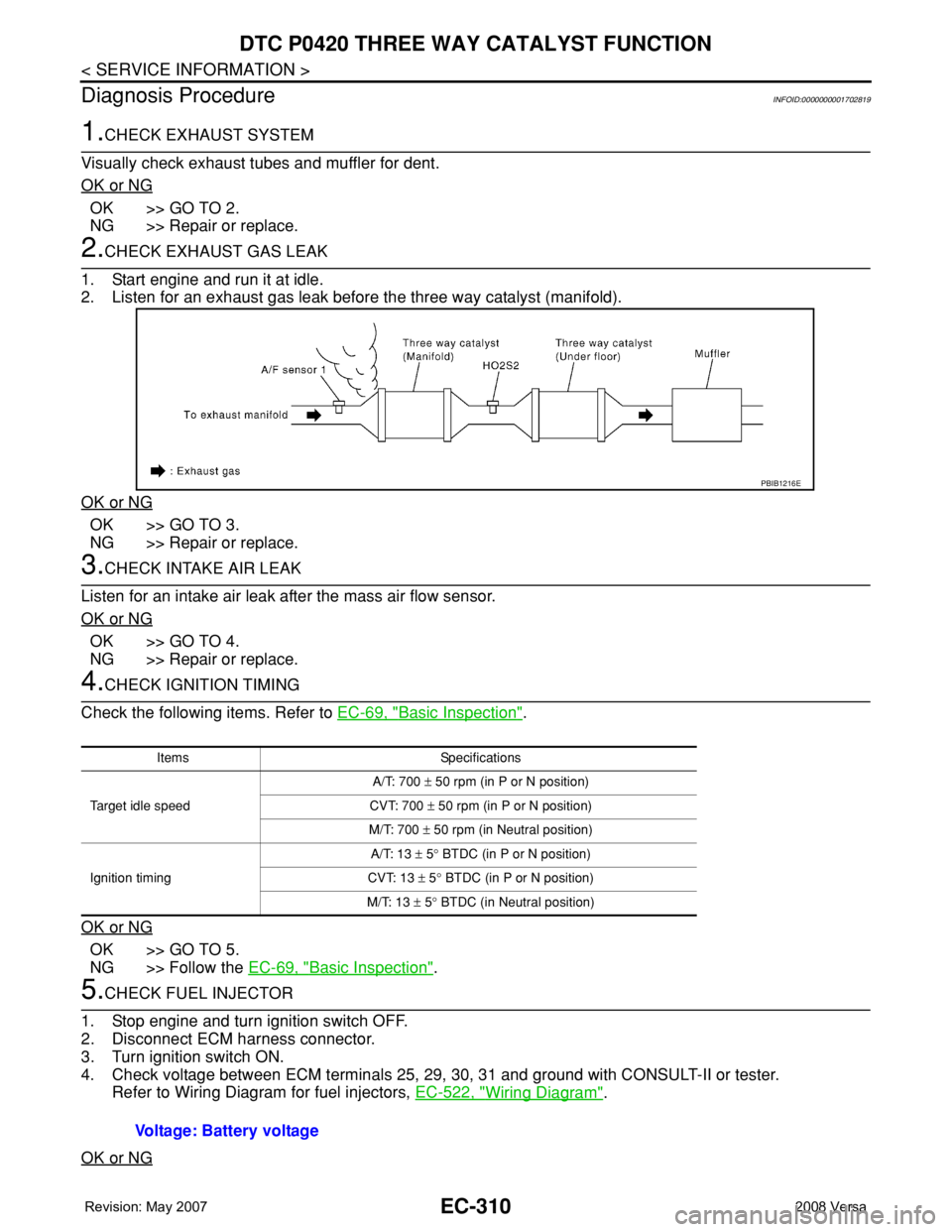
2.CHECK EXHAUST GAS LEAK
1. Start engine and run it at idle.
2. Listen for an exhaust gas leak before the three way catalyst (manifold).
OK or NG
OK >> GO TO 3.
NG >> Repair or replace.
3.CHECK INTAKE AIR LEAK
Listen for an intake air leak after the mass air flow sensor.
OK or NG
OK >> GO TO 4.
NG >> Repair or replace.
4.CHECK IGNITION TIMING
Check the following items. Refer to EC-69, "
Basic Inspection".
OK or NG
OK >> GO TO 5.
NG >> Follow the EC-69, "
Basic Inspection".
5.CHECK FUEL INJECTOR
1. Stop engine and turn ignition switch OFF.
2. Disconnect ECM harness connector.
3. Turn ignition switch ON.
4. Check voltage between ECM terminals 25, 29, 30, 31 and ground with CONSULT-II or tester.
Refer to Wiring Diagram for fuel injectors, EC-522, "
Wiring Diagram".
OK or NG
PBIB1216E
Items Specifications
Target idle speedA/T: 700 ± 50 rpm (in P or N position)
CVT: 700 ± 50 rpm (in P or N position)
M/T: 700 ± 50 rpm (in Neutral position)
Ignition timingA/T: 13 ± 5° BTDC (in P or N position)
CVT: 13 ± 5° BTDC (in P or N position)
M/T: 13 ± 5° BTDC (in Neutral position)
Voltage: Battery voltage