2008 NISSAN TIIDA Engine timing
[x] Cancel search: Engine timingPage 1734 of 2771
CAMSHAFT
EM-57
< SERVICE INFORMATION >
C
D
E
F
G
H
I
J
K
L
MA
EM
N
P O
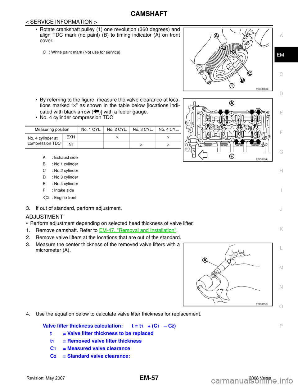
• Rotate crankshaft pulley (1) one revolution (360 degrees) and
align TDC mark (no paint) (B) to timing indicator (A) on front
cover.
• By referring to the figure, measure the valve clearance at loca-
tions marked “×” as shown in the table below [locations indi-
cated with black arrow ( )] with a feeler gauge.
• No. 4 cylinder compression TDC
3. If out of standard, perform adjustment.
ADJUSTMENT
• Perform adjustment depending on selected head thickness of valve lifter.
1. Remove camshaft. Refer to EM-47, "
Removal and Installation".
2. Remove valve lifters at the locations that are out of the standard.
3. Measure the center thickness of the removed valve lifters with a
micrometer (A).
4. Use the equation below to calculate valve lifter thickness for replacement.
C : White paint mark (Not use for service)
PBIC3960E
Measuring position No. 1 CYL. No. 2 CYL. No. 3 CYL. No. 4 CYL.
No. 4 cylinder at
compression TDCEXH × ×
INT × ×
A : Exhaust side
B : No.1 cylinder
C : No.2 cylinder
D : No.3 cylinder
E : No.4 cylinder
F : Intake side
: Engine front
PBIC3194J
PBIC3195J
Valve lifter thickness calculation: t = t1 + (C1 – C2)
t = Valve lifter thickness to be replaced
t
1 = Removed valve lifter thickness
C
1= Measured valve clearance
C
2= Standard valve clearance:
Page 1736 of 2771
OIL SEAL
EM-59
< SERVICE INFORMATION >
C
D
E
F
G
H
I
J
K
L
MA
EM
N
P O
OIL SEAL
Removal and Installation of Valve Oil SealINFOID:0000000001702498
REMOVAL
1. Remove camshafts. Refer to EM-47, "Component".
2. Remove valve lifters. Refer to EM-47
.
3. Rotate crankshaft, and set piston whose valve oil seal is to be removed to TDC. This will prevent valve
from dropping into cylinder.
CAUTION:
When rotating crankshaft, be careful to avoid scarring front cover with timing chain.
4. Remove valve collet.
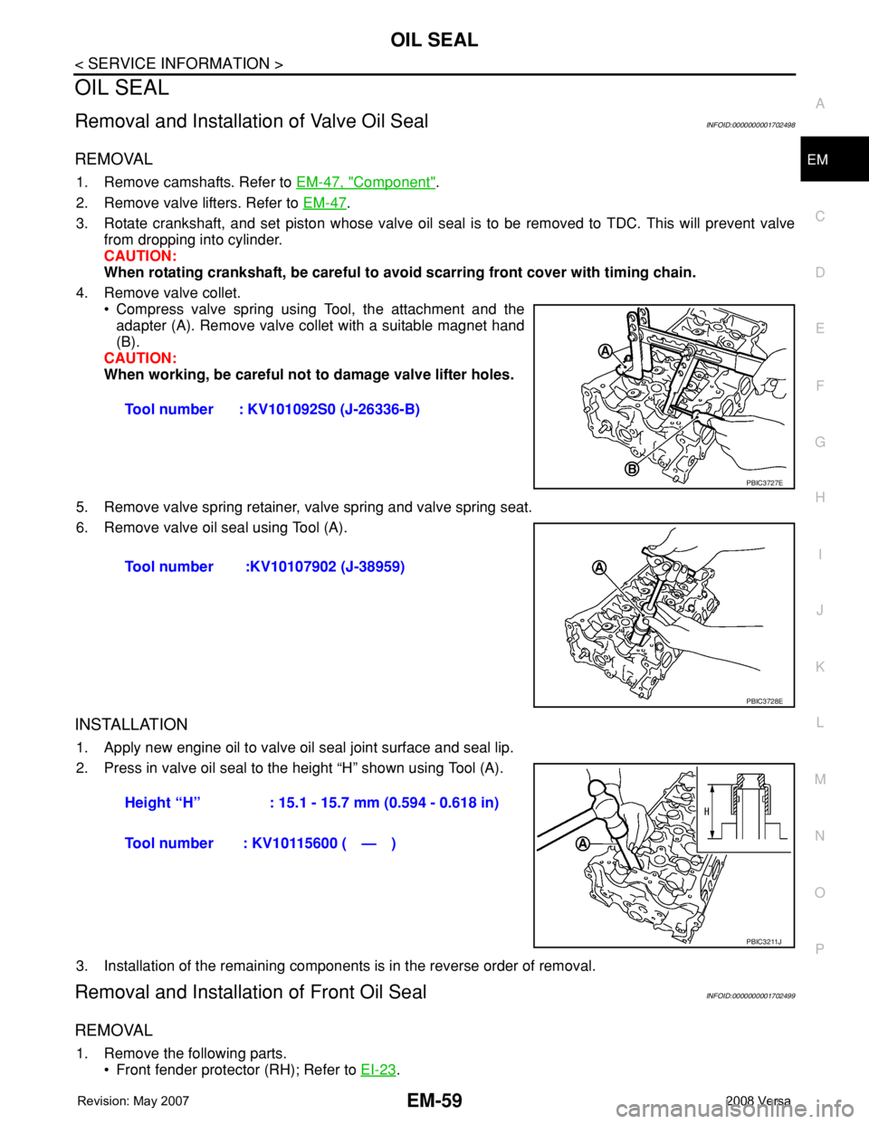
• Compress valve spring using Tool, the attachment and the
adapter (A). Remove valve collet with a suitable magnet hand
(B).
CAUTION:
When working, be careful not to damage valve lifter holes.
5. Remove valve spring retainer, valve spring and valve spring seat.
6. Remove valve oil seal using Tool (A).
INSTALLATION
1. Apply new engine oil to valve oil seal joint surface and seal lip.
2. Press in valve oil seal to the height “H” shown using Tool (A).
3. Installation of the remaining components is in the reverse order of removal.
Removal and Installation of Front Oil SealINFOID:0000000001702499
REMOVAL
1. Remove the following parts.
• Front fender protector (RH); Refer to EI-23
. Tool number : KV101092S0 (J-26336-B)
PBIC3727E
Tool number :KV10107902 (J-38959)
PBIC3728E
Height “H” : 15.1 - 15.7 mm (0.594 - 0.618 in)
Tool number : KV10115600 ( — )
PBIC3211J
Page 1741 of 2771
EM-64
< SERVICE INFORMATION >
CYLINDER HEAD
• Water outlet; Refer to CO-19.
• Rocker cover; Refer to EM-30
.
• Front cover, timing chain; Refer to EM-37
.
• Camshaft; Refer to EM-47
.
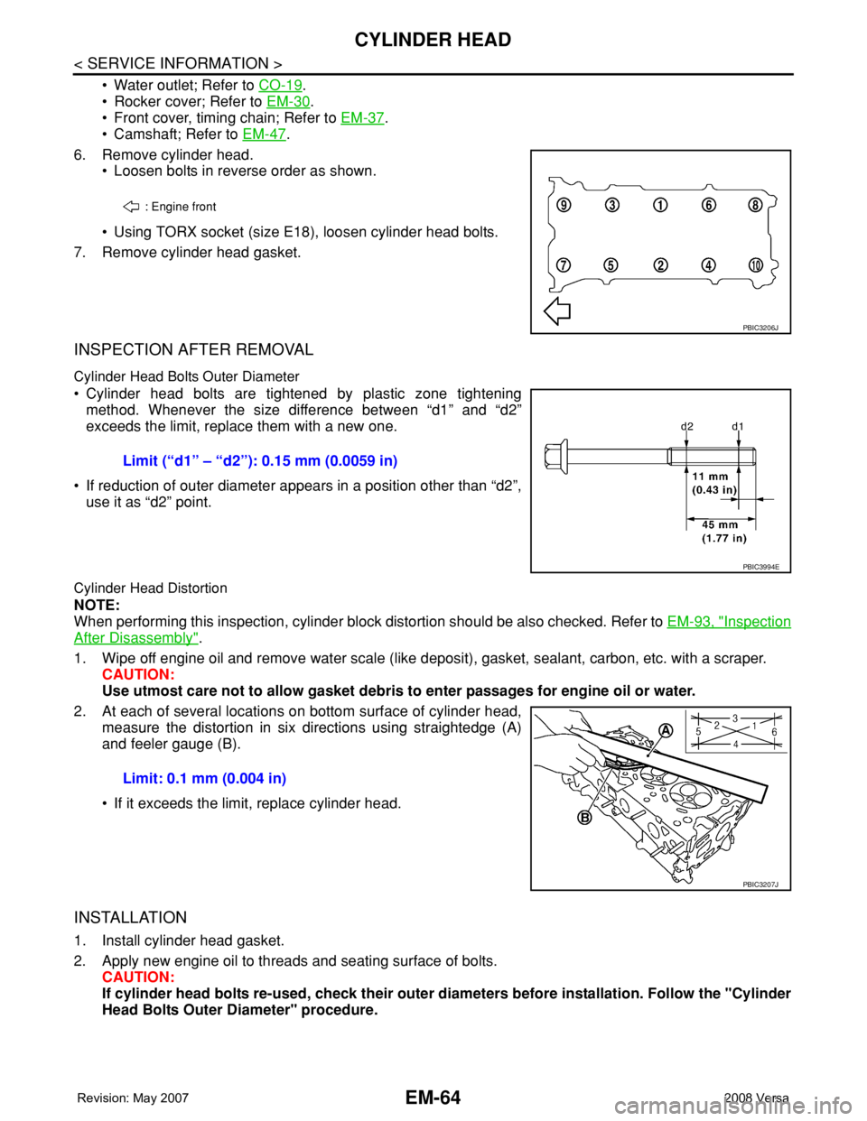
6. Remove cylinder head.
• Loosen bolts in reverse order as shown.
• Using TORX socket (size E18), loosen cylinder head bolts.
7. Remove cylinder head gasket.
INSPECTION AFTER REMOVAL
Cylinder Head Bolts Outer Diameter
• Cylinder head bolts are tightened by plastic zone tightening
method. Whenever the size difference between “d1” and “d2”
exceeds the limit, replace them with a new one.
• If reduction of outer diameter appears in a position other than “d2”,
use it as “d2” point.
Cylinder Head Distortion
NOTE:
When performing this inspection, cylinder block distortion should be also checked. Refer to EM-93, "
Inspection
After Disassembly".
1. Wipe off engine oil and remove water scale (like deposit), gasket, sealant, carbon, etc. with a scraper.
CAUTION:
Use utmost care not to allow gasket debris to enter passages for engine oil or water.
2. At each of several locations on bottom surface of cylinder head,
measure the distortion in six directions using straightedge (A)
and feeler gauge (B).
• If it exceeds the limit, replace cylinder head.
INSTALLATION
1. Install cylinder head gasket.
2. Apply new engine oil to threads and seating surface of bolts.
CAUTION:
If cylinder head bolts re-used, check their outer diameters before installation. Follow the "Cylinder
Head Bolts Outer Diameter" procedure.
: Engine front
PBIC3206J
Limit (“d1” – “d2”): 0.15 mm (0.0059 in)
PBIC3994E
Limit: 0.1 mm (0.004 in)
PBIC3207J
Page 1762 of 2771
CYLINDER BLOCK
EM-85
< SERVICE INFORMATION >
C
D
E
F
G
H
I
J
K
L
MA
EM
N
P O
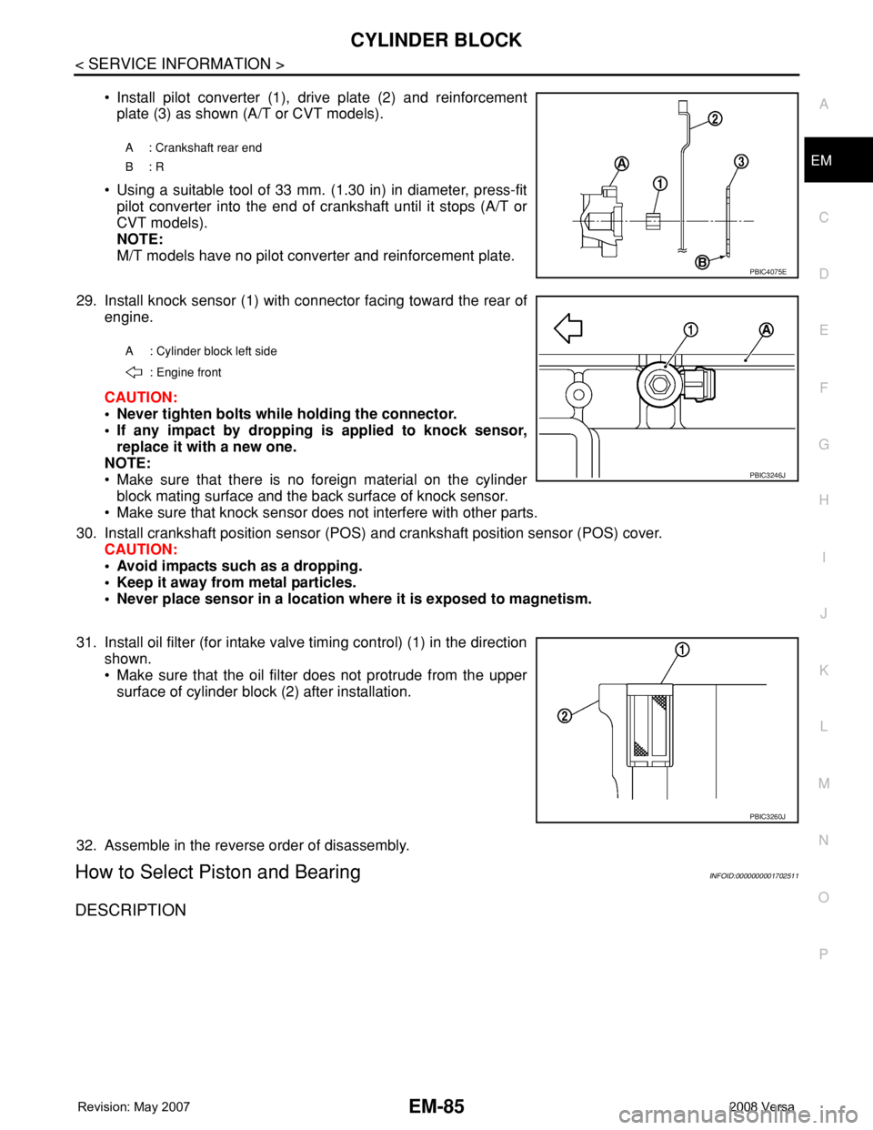
• Install pilot converter (1), drive plate (2) and reinforcement
plate (3) as shown (A/T or CVT models).
• Using a suitable tool of 33 mm. (1.30 in) in diameter, press-fit
pilot converter into the end of crankshaft until it stops (A/T or
CVT models).
NOTE:
M/T models have no pilot converter and reinforcement plate.
29. Install knock sensor (1) with connector facing toward the rear of
engine.
CAUTION:
• Never tighten bolts while holding the connector.
• If any impact by dropping is applied to knock sensor,
replace it with a new one.
NOTE:
• Make sure that there is no foreign material on the cylinder
block mating surface and the back surface of knock sensor.
• Make sure that knock sensor does not interfere with other parts.
30. Install crankshaft position sensor (POS) and crankshaft position sensor (POS) cover.
CAUTION:
• Avoid impacts such as a dropping.
• Keep it away from metal particles.
• Never place sensor in a location where it is exposed to magnetism.
31. Install oil filter (for intake valve timing control) (1) in the direction
shown.
• Make sure that the oil filter does not protrude from the upper
surface of cylinder block (2) after installation.
32. Assemble in the reverse order of disassembly.
How to Select Piston and BearingINFOID:0000000001702511
DESCRIPTION
A : Crankshaft rear end
B: R
PBIC4075E
A : Cylinder block left side
: Engine front
PBIC3246J
PBIC3260J
Page 1898 of 2771

TERMINOLOGY
GI-47
< SERVICE INFORMATION >
C
D
E
F
G
H
I
J
K
L
MB
GI
N
O
PTERMINOLOGY
SAE J1930 Terminology ListINFOID:0000000001702459
All emission related terms used in this publication in accordance with SAE J1930 are listed. Accordingly, new
terms, new acronyms/abbreviations and old terms are listed in the following chart.
NEW TERMNEW ACRONYM /
ABBREVIATIONOLD TERM
Air cleaner ACL Air cleaner
Barometric pressure BARO ***
Barometric pressure sensor-BCDD BAROS-BCDD BCDD
Camshaft position CMP ***
Camshaft position sensor CMPS Crank angle sensor
Canister *** Canister
Carburetor CARB Carburetor
Charge air cooler CAC Intercooler
Closed loop CL Closed loop
Closed throttle position switch CTP switch Idle switch
Clutch pedal position switch CPP switch Clutch switch
Continuous fuel injection system CFI system ***
Continuous trap oxidizer system CTOX system ***
Crankshaft position CKP ***
Crankshaft position sensor CKPS ***
Data link connector DLC ***
Data link connector for CONSULT-III DLC for CONSULT-III Diagnostic connector for CONSULT-III
Diagnostic test mode DTM Diagnostic mode
Diagnostic test mode selector DTM selector Diagnostic mode selector
Diagnostic test mode I DTM I Mode I
Diagnostic test mode II DTM II Mode II
Diagnostic trouble code DTC Malfunction code
Direct fuel injection system DFI system ***
Distributor ignition system DI system Ignition timing control
Early fuel evaporation-mixture heater EFE-mixture heater Mixture heater
Early fuel evaporation system EFE system Mixture heater control
Electrically erasable programmable read
only memoryEEPROM ***
Electronic ignition system EI system Ignition timing control
Engine control EC ***
Engine control module ECM ECCS control unit
Engine coolant temperature ECT Engine temperature
Engine coolant temperature sensor ECTS Engine temperature sensor
Engine modification EM ***
Engine speed RPM Engine speed
Erasable programmable read only memory EPROM ***
Evaporative emission canister EVAP canister Canister
Evaporative emission system EVAP system Canister control solenoid valve
Exhaust gas recirculation valve EGR valve EGR valve
Page 2256 of 2771
LU-6
< SERVICE INFORMATION >
ENGINE OIL
ENGINE OIL
InspectionINFOID:0000000001702518
ENGINE OIL LEVEL
NOTE:
Before starting engine, park vehicle on a level surface and check the engine oil level. If engine is already
started, stop it and allow 10 minutes before checking.
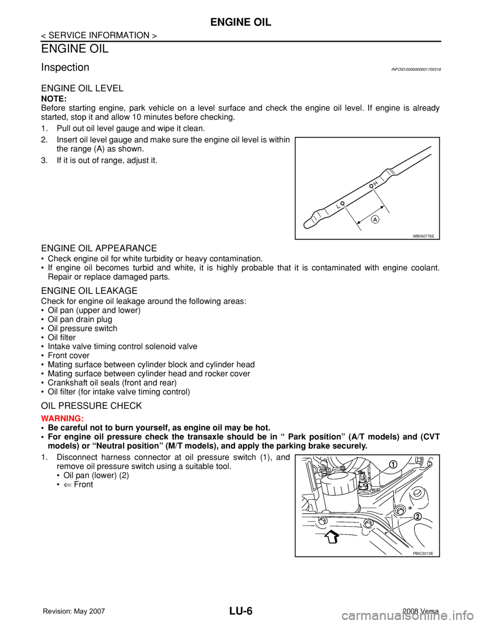
1. Pull out oil level gauge and wipe it clean.
2. Insert oil level gauge and make sure the engine oil level is within
the range (A) as shown.
3. If it is out of range, adjust it.
ENGINE OIL APPEARANCE
• Check engine oil for white turbidity or heavy contamination.
• If engine oil becomes turbid and white, it is highly probable that it is contaminated with engine coolant.
Repair or replace damaged parts.
ENGINE OIL LEAKAGE
Check for engine oil leakage around the following areas:
• Oil pan (upper and lower)
• Oil pan drain plug
• Oil pressure switch
• Oil filter
• Intake valve timing control solenoid valve
• Front cover
• Mating surface between cylinder block and cylinder head
• Mating surface between cylinder head and rocker cover
• Crankshaft oil seals (front and rear)
• Oil filter (for intake valve timing control)
OIL PRESSURE CHECK
WARNING:
• Be careful not to burn yourself, as engine oil may be hot.
• For engine oil pressure check the transaxle should be in “ Park position” (A/T models) and (CVT
models) or “Neutral position” (M/T models), and apply the parking brake securely.
1. Disconnect harness connector at oil pressure switch (1), and
remove oil pressure switch using a suitable tool.
• Oil pan (lower) (2)
•⇐ Front
WBIA0776E
PBIC3310E
Page 2426 of 2771
MTC-88
< SERVICE INFORMATION >
SERVICE DATA AND SPECIFICATIONS (SDS)
SERVICE DATA AND SPECIFICATIONS (SDS)
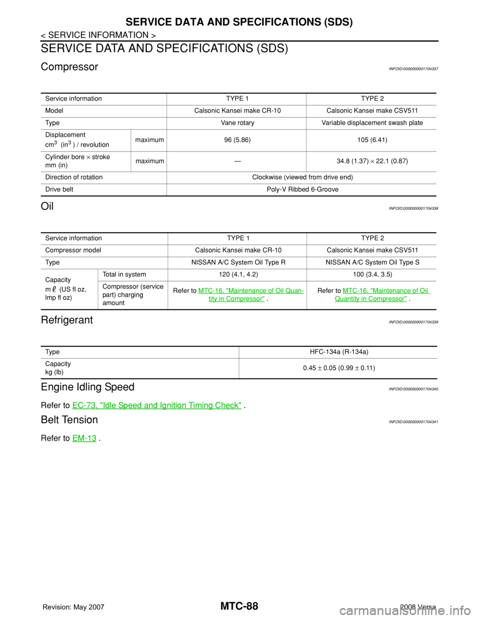
CompressorINFOID:0000000001704337
OilINFOID:0000000001704338
RefrigerantINFOID:0000000001704339
Engine Idling SpeedINFOID:0000000001704340
Refer to EC-73, "Idle Speed and Ignition Timing Check" .
Belt TensionINFOID:0000000001704341
Refer to EM-13 .
Service information TYPE 1 TYPE 2
Model Calsonic Kansei make CR-10 Calsonic Kansei make CSV511
Type Vane rotary Variable displacement swash plate
Displacement
cm
3 (in3 ) / revolutionmaximum 96 (5.86) 105 (6.41)
Cylinder bore × stroke
mm (in)maximum — 34.8 (1.37) × 22.1 (0.87)
Direction of rotation Clockwise (viewed from drive end)
Drive belt Poly-V Ribbed 6-Groove
Service information TYPE 1 TYPE 2
Compressor model Calsonic Kansei make CR-10 Calsonic Kansei make CSV511
Type NISSAN A/C System Oil Type R NISSAN A/C System Oil Type S
Capacity
m (US fl oz,
lmp fl oz)Total in system 120 (4.1, 4.2) 100 (3.4, 3.5)
Compressor (service
part) charging
amountRefer to MTC-16, "
Maintenance of Oil Quan-
tity in Compressor" .Refer to MTC-16, "
Maintenance of Oil
Quantity in Compressor" .
Ty p eHFC-134a (R-134a)
Capacity
kg (lb)0.45 ± 0.05 (0.99 ± 0.11)
Page 2478 of 2771
HARNESS
PG-45
< SERVICE INFORMATION >
C
D
E
F
G
H
I
J
L
MA
B
PG
N
O
P
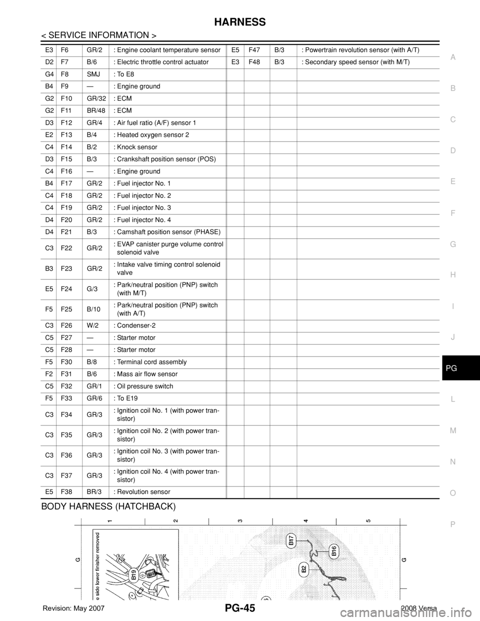
BODY HARNESS (HATCHBACK)
E3 F6 GR/2 : Engine coolant temperature sensor E5 F47 B/3 : Powertrain revolution sensor (with A/T)
D2 F7 B/6 : Electric throttle control actuatorE3 F48 B/3 : Secondary speed sensor (with M/T)
G4 F8 SMJ : To E8
B4 F9 — : Engine ground
G2 F10 GR/32 : ECM
G2 F11 BR/48 : ECM
D3 F12 GR/4 : Air fuel ratio (A/F) sensor 1
E2 F13 B/4 : Heated oxygen sensor 2
C4 F14 B/2 : Knock sensor
D3 F15 B/3 : Crankshaft position sensor (POS)
C4 F16 — : Engine ground
B4 F17 GR/2 : Fuel injector No. 1
C4 F18 GR/2 : Fuel injector No. 2
C4 F19 GR/2 : Fuel injector No. 3
D4 F20 GR/2 : Fuel injector No. 4
D4 F21 B/3 : Camshaft position sensor (PHASE)
C3 F22 GR/2: EVAP canister purge volume control
solenoid valve
B3 F23 GR/2: Intake valve timing control solenoid
valve
E5 F24 G/3: Park/neutral position (PNP) switch
(with M/T)
F5 F25 B/10: Park/neutral position (PNP) switch
(with A/T)
C3 F26 W/2 : Condenser-2
C5 F27 — : Starter motor
C5 F28 — : Starter motor
F5 F30 B/8 : Terminal cord assembly
F2 F31 B/6 : Mass air flow sensor
C5 F32 GR/1 : Oil pressure switch
F5 F33 GR/6 : To E19
C3 F34 GR/3: Ignition coil No. 1 (with power tran-
sistor)
C3 F35 GR/3: Ignition coil No. 2 (with power tran-
sistor)
C3 F36 GR/3: Ignition coil No. 3 (with power tran-
sistor)
C3 F37 GR/3: Ignition coil No. 4 (with power tran-
sistor)
E5 F38 BR/3 : Revolution sensor