2008 NISSAN TIIDA Glove
[x] Cancel search: GlovePage 28 of 2771
AT-16
< SERVICE INFORMATION >
A/T FLUID
5. Run engine at idle speed for 5 minutes.
6. Check A/T fluid level and condition. Refer to MA-22, "
Checking A/T Fluid".
A/T Fluid Cooler CleaningINFOID:0000000001703160
Whenever the A/T is repaired, overhauled, or replaced, the A/T fluid cooler mounted in the radiator must be
inspected and cleaned.
Metal debris and friction material, if present, can become trapped in the A/T fluid cooler. This debris can con-
taminate the newly serviced A/T or, in severe cases, can block or restrict the flow of A/T fluid. In either case,
malfunction of the newly serviced A/T may result.
Debris, if present, may build up as A/T fluid enters the cooler inlet. It will be necessary to back flush the cooler
through the cooler outlet in order to flush out any built up debris.
A/T FLUID COOLER CLEANING PROCEDURE
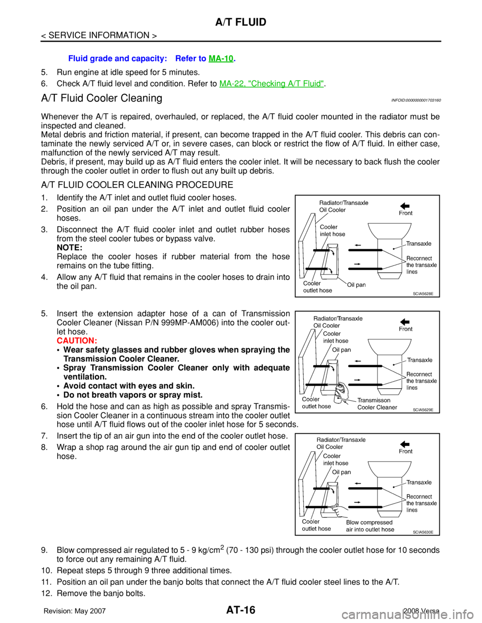
1. Identify the A/T inlet and outlet fluid cooler hoses.
2. Position an oil pan under the A/T inlet and outlet fluid cooler
hoses.
3. Disconnect the A/T fluid cooler inlet and outlet rubber hoses
from the steel cooler tubes or bypass valve.
NOTE:
Replace the cooler hoses if rubber material from the hose
remains on the tube fitting.
4. Allow any A/T fluid that remains in the cooler hoses to drain into
the oil pan.
5. Insert the extension adapter hose of a can of Transmission
Cooler Cleaner (Nissan P/N 999MP-AM006) into the cooler out-
let hose.
CAUTION:
• Wear safety glasses and rubber gloves when spraying the
Transmission Cooler Cleaner.
• Spray Transmission Cooler Cleaner only with adequate
ventilation.
• Avoid contact with eyes and skin.
• Do not breath vapors or spray mist.
6. Hold the hose and can as high as possible and spray Transmis-
sion Cooler Cleaner in a continuous stream into the cooler outlet
hose until A/T fluid flows out of the cooler inlet hose for 5 seconds.
7. Insert the tip of an air gun into the end of the cooler outlet hose.
8. Wrap a shop rag around the air gun tip and end of cooler outlet
hose.
9. Blow compressed air regulated to 5 - 9 kg/cm
2 (70 - 130 psi) through the cooler outlet hose for 10 seconds
to force out any remaining A/T fluid.
10. Repeat steps 5 through 9 three additional times.
11. Position an oil pan under the banjo bolts that connect the A/T fluid cooler steel lines to the A/T.
12. Remove the banjo bolts.Fluid grade and capacity: Refer to MA-10
.
SCIA5628E
SCIA5629E
SCIA5630E
Page 29 of 2771
A/T FLUID
AT-17
< SERVICE INFORMATION >
D
E
F
G
H
I
J
K
L
MA
B
AT
N
O
P
13. Flush each steel line from the cooler side back toward the A/T by spraying Transmission Cooler Cleaner
in a continuous stream for 5 seconds.
14. Blow compressed air regulated to 5 - 9 kg/cm
2 (70 - 130 psi) through each steel line from the cooler side
back toward the A/T for 10 seconds to force out any remaining A/T fluid.
15. Ensure all debris is removed from the steel cooler lines.
16. Ensure all debris is removed from the banjo bolts and fittings.
17. Perform "A/T FLUID COOLER DIAGNOSIS PROCEDURE".
A/T FLUID COOLER DIAGNOSIS PROCEDURE
NOTE:
Insufficient cleaning of the cooler inlet hose exterior may lead to inaccurate debris identification.
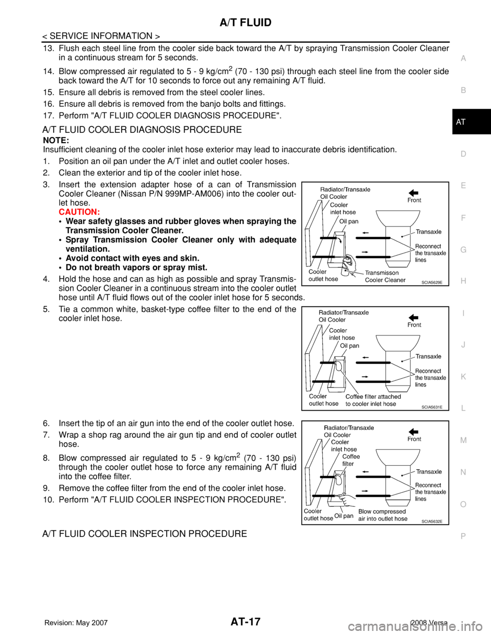
1. Position an oil pan under the A/T inlet and outlet cooler hoses.
2. Clean the exterior and tip of the cooler inlet hose.
3. Insert the extension adapter hose of a can of Transmission
Cooler Cleaner (Nissan P/N 999MP-AM006) into the cooler out-
let hose.
CAUTION:
• Wear safety glasses and rubber gloves when spraying the
Transmission Cooler Cleaner.
• Spray Transmission Cooler Cleaner only with adequate
ventilation.
• Avoid contact with eyes and skin.
• Do not breath vapors or spray mist.
4. Hold the hose and can as high as possible and spray Transmis-
sion Cooler Cleaner in a continuous stream into the cooler outlet
hose until A/T fluid flows out of the cooler inlet hose for 5 seconds.
5. Tie a common white, basket-type coffee filter to the end of the
cooler inlet hose.
6. Insert the tip of an air gun into the end of the cooler outlet hose.
7. Wrap a shop rag around the air gun tip and end of cooler outlet
hose.
8. Blow compressed air regulated to 5 - 9 kg/cm
2 (70 - 130 psi)
through the cooler outlet hose to force any remaining A/T fluid
into the coffee filter.
9. Remove the coffee filter from the end of the cooler inlet hose.
10. Perform "A/T FLUID COOLER INSPECTION PROCEDURE".
A/T FLUID COOLER INSPECTION PROCEDURE
SCIA5629E
SCIA5631E
SCIA5632E
Page 434 of 2771
BCS-18
< SERVICE INFORMATION >
BCM (BODY CONTROL MODULE)
• WRITE CONFIGURATION-Manual selection is the function to select and write vehicle configuration on BCM
manually.
• WRITE CONFIGURATION-Config file is the function to write vehicle configuration with the data extracted
from current BCM.
• For READ CONFIGURATION and WRITE CONFIGURATION-Config file, refer to CONSULT-III Operation
Manual.
• For WRITE CONFIGURATION-Manual selection using the following flow chart, identify the correct model
and configuration list. Confirm and/or change setting value for each item according to the configuration list.
Depending on CONSULT-III software version being used, some or all of the write configuration items shown
in the following configuration lists may be displayed. If an item does not appear on the CONSULT-III WRITE
CONFIGURATION-Manual selection screen(s), then it is an auto setting item and it cannot be manually set
or changed.
NOTE:
Confirm vehicle model on IDENTIFICATION PLATE. Refer to GI-43, "
Model Variation".
CAUTION:
• When replacing BCM, you must perform WRITE CONFIGURATION with CONSULT-III.
• Complete the procedure of WRITE CONFIGURATION in order.
• If you set incorrect WRITE CONFIGURATION, incidents will occur.
• Configuration is different for each vehicle model. Confirm configuration of each vehicle model.
Removal and Installation of BCMINFOID:0000000001704593
REMOVAL
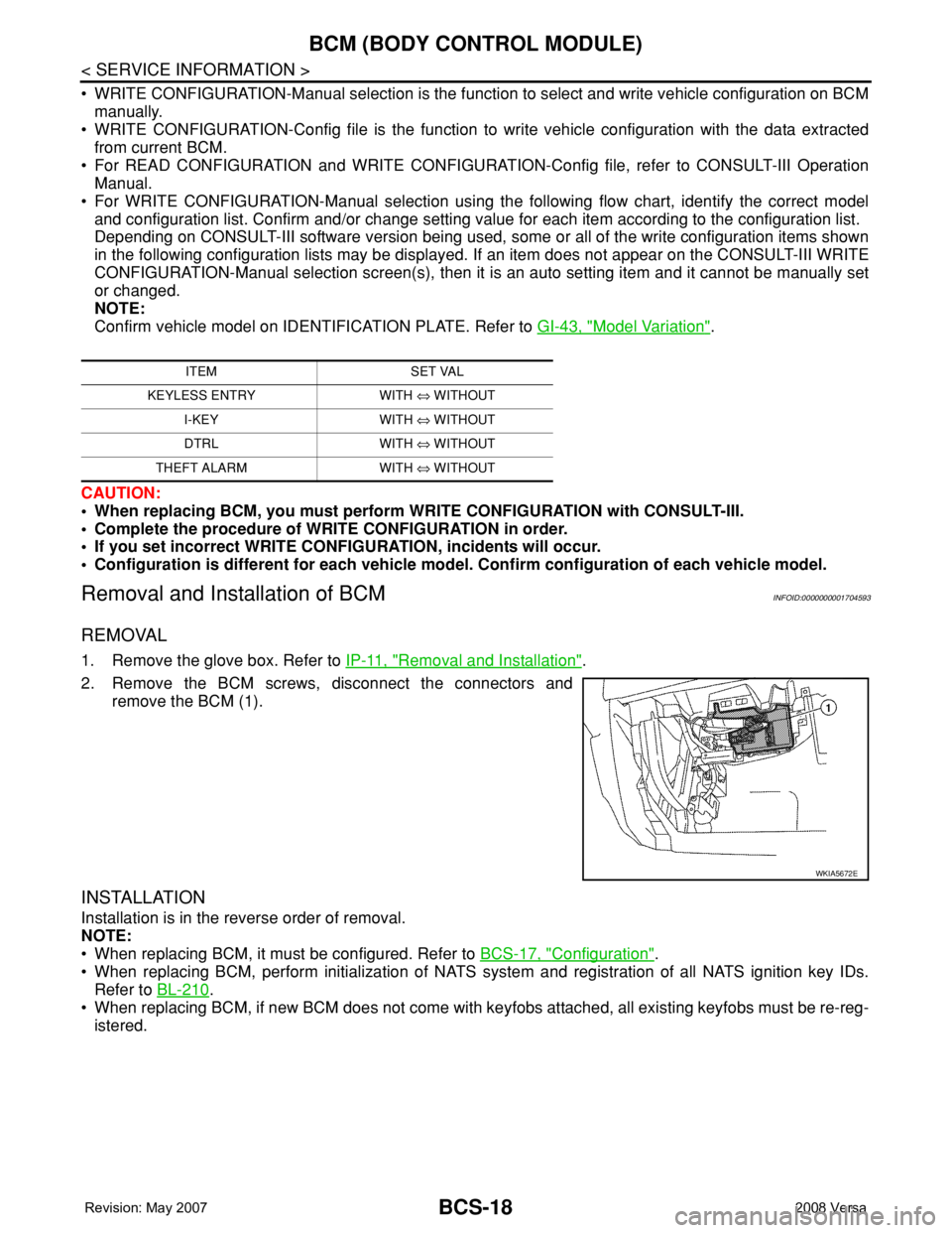
1. Remove the glove box. Refer to IP-11, "Removal and Installation".
2. Remove the BCM screws, disconnect the connectors and
remove the BCM (1).
INSTALLATION
Installation is in the reverse order of removal.
NOTE:
• When replacing BCM, it must be configured. Refer to BCS-17, "
Configuration".
• When replacing BCM, perform initialization of NATS system and registration of all NATS ignition key IDs.
Refer to BL-210
.
• When replacing BCM, if new BCM does not come with keyfobs attached, all existing keyfobs must be re-reg-
istered.
ITEM SET VAL
KEYLESS ENTRY WITH ⇔ WITHOUT
I-KEY WITH ⇔ WITHOUT
DTRL WITH ⇔ WITHOUT
THEFT ALARM WITH ⇔ WITHOUT
WKIA5672E
Page 456 of 2771
BL-22
< SERVICE INFORMATION >
POWER DOOR LOCK SYSTEM
POWER DOOR LOCK SYSTEM
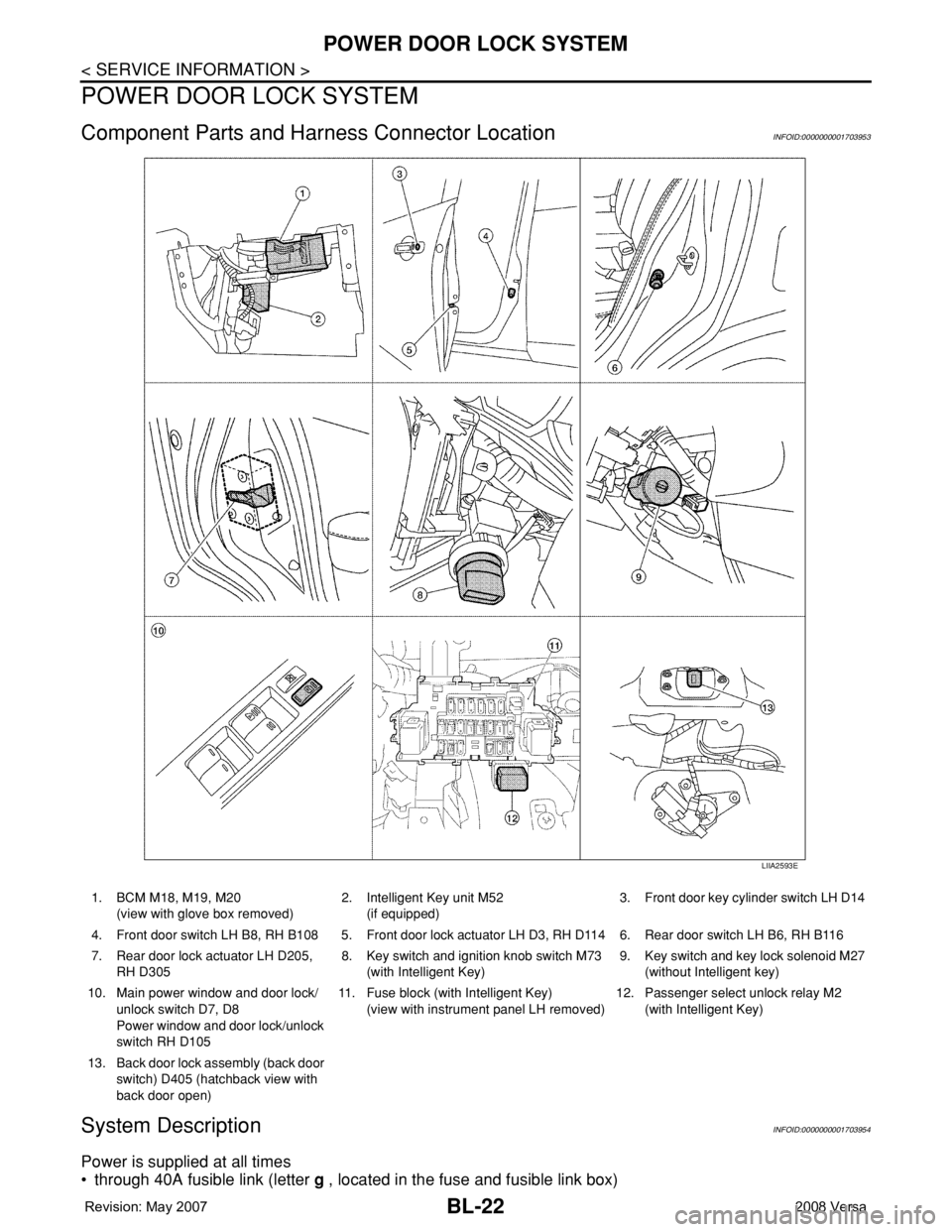
Component Parts and Harness Connector LocationINFOID:0000000001703953
System DescriptionINFOID:0000000001703954
Power is supplied at all times
• through 40A fusible link (letter g , located in the fuse and fusible link box)
LIIA2593E
1. BCM M18, M19, M20
(view with glove box removed)2. Intelligent Key unit M52
(if equipped)3. Front door key cylinder switch LH D14
4. Front door switch LH B8, RH B108 5. Front door lock actuator LH D3, RH D114 6. Rear door switch LH B6, RH B116
7. Rear door lock actuator LH D205,
RH D3058. Key switch and ignition knob switch M73
(with Intelligent Key)9. Key switch and key lock solenoid M27
(without Intelligent key)
10. Main power window and door lock/
unlock switch D7, D8
Power window and door lock/unlock
switch RH D10511. Fuse block (with Intelligent Key)
(view with instrument panel LH removed)12. Passenger select unlock relay M2
(with Intelligent Key)
13. Back door lock assembly (back door
switch) D405 (hatchback view with
back door open)
Page 485 of 2771
REMOTE KEYLESS ENTRY SYSTEM
BL-51
< SERVICE INFORMATION >
C
D
E
F
G
H
J
K
L
MA
B
BL
N
O
P
REMOTE KEYLESS ENTRY SYSTEM
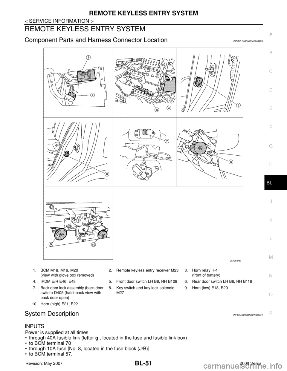
Component Parts and Harness Connector LocationINFOID:0000000001703973
System DescriptionINFOID:0000000001703974
INPUTS
Power is supplied at all times
• through 40A fusible link (letter g , located in the fuse and fusible link box)
• to BCM terminal 70
• through 10A fuse [No. 8, located in the fuse block (J/B)]
• to BCM terminal 57.
LIIA2594E
1. BCM M18, M19, M20
(view with glove box removed)2. Remote keyless entry receiver M23 3. Horn relay H-1
(front of battery)
4. IPDM E/R E46, E48 5. Front door switch LH B8, RH B108 6. Rear door switch LH B6, RH B116
7. Back door lock assembly (back door
switch) D405 (hatchback view with
back door open)8. Key switch and key lock solenoid
M279. Horn (low) E18, E20
10. Horn (high) E21, E22
Page 507 of 2771
REMOTE KEYLESS ENTRY SYSTEM
BL-73
< SERVICE INFORMATION >
C
D
E
F
G
H
J
K
L
MA
B
BL
N
O
P
To erase all ID codes in memory, register one ID code (keyfob) five times. After all ID codes are erased, the
ID codes of all remaining and/or new keyfobs must be re-registered.
• When registering an additional keyfob, the existing ID codes in memory may or may not be erased. If five ID
codes are stored in memory, when an additional code is registered, only the oldest code is erased. If less
than five ID codes are stored in memory, when an additional ID code is registered, the new ID code is added
and no ID codes are erased.
• If you need to activate more than two additional new keyfobs, repeat the procedure “Additional ID code
entry” for each new keyfob.
• Entry of maximum five ID codes is allowed. When more than five ID codes are entered, the oldest ID code
will be erased.
• Even if same ID code that is already in the memory is input, the same ID code can be entered. The code is
counted as an additional code.
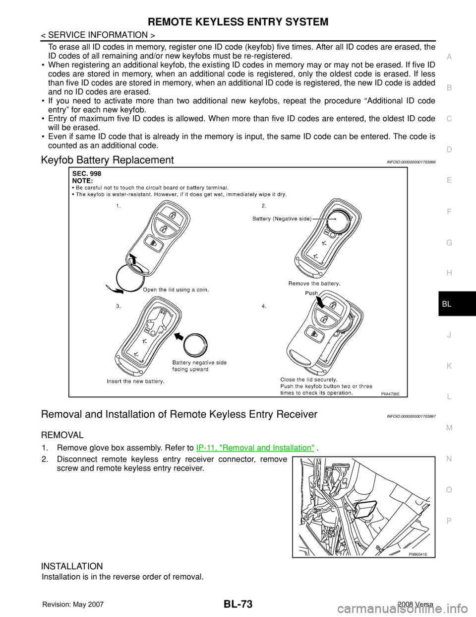
Keyfob Battery ReplacementINFOID:0000000001703996
Removal and Installation of Remote Keyless Entry ReceiverINFOID:0000000001703997
REMOVAL
1. Remove glove box assembly. Refer to IP-11, "Removal and Installation" .
2. Disconnect remote keyless entry receiver connector, remove
screw and remote keyless entry receiver.
INSTALLATION
Installation is in the reverse order of removal.
PIIA4706E
PIIB6541E
Page 509 of 2771
INTELLIGENT KEY SYSTEM
BL-75
< SERVICE INFORMATION >
C
D
E
F
G
H
J
K
L
MA
B
BL
N
O
P
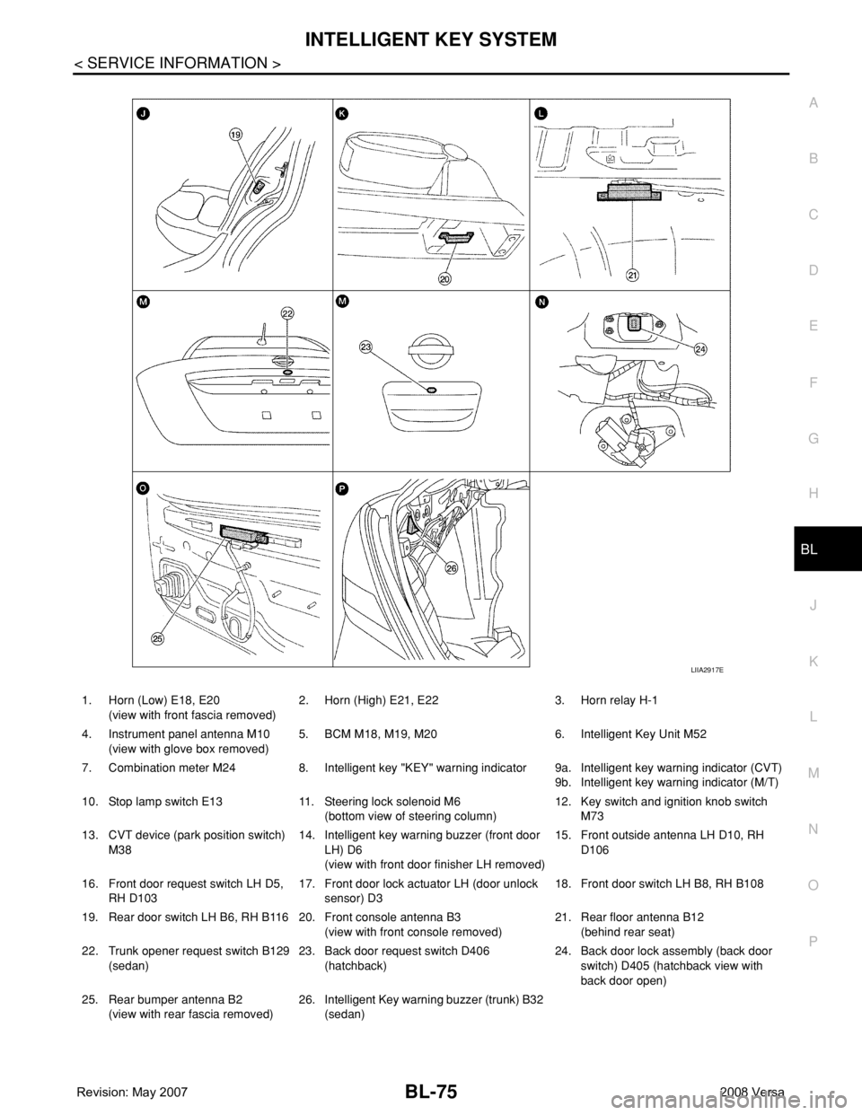
1. Horn (Low) E18, E20
(view with front fascia removed)2. Horn (High) E21, E22 3. Horn relay H-1
4. Instrument panel antenna M10
(view with glove box removed)5. BCM M18, M19, M20 6. Intelligent Key Unit M52
7. Combination meter M24 8. Intelligent key "KEY" warning indicator 9a.
9b.Intelligent key warning indicator (CVT)
Intelligent key warning indicator (M/T)
10. Stop lamp switch E13 11. Steering lock solenoid M6
(bottom view of steering column)12. Key switch and ignition knob switch
M73
13. CVT device (park position switch)
M3814. Intelligent key warning buzzer (front door
LH) D6
(view with front door finisher LH removed)15. Front outside antenna LH D10, RH
D106
16. Front door request switch LH D5,
RH D10317. Front door lock actuator LH (door unlock
sensor) D318. Front door switch LH B8, RH B108
19. Rear door switch LH B6, RH B116 20. Front console antenna B3
(view with front console removed)21. Rear floor antenna B12
(behind rear seat)
22. Trunk opener request switch B129
(sedan)23. Back door request switch D406
(hatchback)24. Back door lock assembly (back door
switch) D405 (hatchback view with
back door open)
25. Rear bumper antenna B2
(view with rear fascia removed)26. Intelligent Key warning buzzer (trunk) B32
(sedan)
LIIA2917E
Page 512 of 2771

BL-78
< SERVICE INFORMATION >
INTELLIGENT KEY SYSTEM
* : Hatchback
** : Sedan
KEY REMINDER FUNCTION
Key reminder functions have the following 2 functions.
CAUTION:
• The above function operates when the Intelligent Key is inside the vehicle. However, there may be
times when the Intelligent Key cannot be detected, and this function will not operate when the Intelli-
gent Key is on the instrument panel, rear parcel shelf or in the glove box. Also, this system some-
times does not operate if the Intelligent Key is in the door pocket of an open door.
List of Operation Related Parts
Parts marked with × are the parts related to operation
REMOTE KEYLESS ENTRY FUNCTIONS
The Intelligent Key has the same functions as the remote keyless entry system. Therefore, it can be used in
the same manner as the keyfob by operating the door lock/unlock button.
Door lock open function
Intelligent Key
Key switch
Ignition knob switch
Door switch
Back door lock assembly (back door switch)
*
Request switch (driver, passenger, back)
Door lock actuator
Inside key antenna
Outside key antenna
Intelligent Key warning buzzer (front door LH)
Intelligent Key warning buzzer (trunk)
**
Intelligent Key unit
CAN communication system
BCM
Hazard warning lamp
Door lock/unlock function by request switch××××××××××
Door lock/unlock function by mechanical key××
Hazard and buzzer reminder function××××××
Auto door lock function×××× × ×××
Key reminder function Operation condition Operation
Door is open to closeRight after all doors are closed under the following conditions.
• Intelligent Key is inside the vehicle
• Any door is opened
• All doors are locked by door lock and unlock switch or door
lock knob• All doors unlock operation
• Sound Intelligent Key warn-
ing buzzer for 3 seconds
Key reminder functions
Intelligent Key
Door switch
Unlock sensor
Door lock actuator
Inside key antenna
Intelligent Key warning buzzer(s)
Intelligent Key unit
CAN communication system
BCM
Any door open to close×××××××××