2008 NISSAN TIIDA lan system
[x] Cancel search: lan systemPage 1 of 2771

-1
QUICK REFERENCE INDEX
AGENERAL INFORMATIONGIGeneral Information
BENGINEEMEngine Mechanical
LUEngine Lubrication System
COEngine Cooling System
ECEngine Control System
FLFuel System
EXExhaust System
ACCAccelerator Control System
CTRANSMISSION/
TRANSAXLECLClutch System
MTManual Transaxle
ATAutomatic Transaxle
CVTCVT
DDRIVELINE/AXLEFAXFront Axle
RAXRear Axle
ESUSPENSIONFSUFront Suspension
RSURear Suspension
WTRoad Wheels & Tires
FBRAKESBRBrake System
PBParking Brake System
BRCBrake Control System
GSTEERINGPSPower Steering System
STCSteering Control System
HRESTRAINTSSBSeat Belts
SRSSupplemental Restraint System (SRS)
IBODYBLBody, Lock & Security System
GWGlasses, Window System & Mirrors
RFRoof
EIExterior & Interior
IPInstrument Panel
SESeat
JAIR CONDITIONERMTCManual Air Conditioner
KELECTRICALSCStarting & Charging System
LTLighting System
DIDriver Information System
WWWiper, Washer & Horn
BCSBody Control System
LANLAN System
AVAudio Visual, Navigation & Telephone System
ACSAuto Cruise Control System
PGPower Supply, Ground & Circuit Elements
LMAINTENANCEMAMaintenance
Edition: May 2007
Revision: May 2007
Publication No. SM8E-1C11U0
B
D
© 2007 NISSAN NORTH AMERICA, INC.
All rights reserved. No part of this Service Manual may be reproduced or stored in a retrieval system, or transmitted in any
form, or by any means, electronic, mechanical, photo-copying, recording or otherwise, without the prior written permission
of Nissan North America Inc.
A
C
E
F
G
H
I
J
K
L
M
Page 21 of 2771

PRECAUTIONS
AT-9
< SERVICE INFORMATION >
D
E
F
G
H
I
J
K
L
MA
B
AT
N
O
P
• Before assembly, apply a coat of recommended ATF to all parts. Apply petroleum jelly to protect O-rings and
seals, or hold bearings and washers in place during assembly. Do not use grease.
• Extreme care should be taken to avoid damage to O-rings, seals and gaskets when assembling.
• Clean or replace ATF cooler if excessive foreign material is found in oil pan or clogging strainer. Refer to
Refer to .
• After overhaul, refill the A/T with new ATF.
• When the A/T drain plug is removed, only some of the fluid is drained. Old A/T fluid will remain in torque con-
verter and ATF cooling system.
Always follow the procedures under “Changing A/T Fluid” in the AT section when changing A/T fluid. Refer to
MA-22, "
Changing A/T Fluid", MA-22, "Checking A/T Fluid".
Service Notice or PrecautionINFOID:0000000001703155
ATF COOLER SERVICE
If A/T fluid contains frictional material (clutches, bands, etc.), or if an A/T is repaired, overhauled, or replaced,
inspect and clean the A/T oil cooler mounted in the radiator or replace the radiator. Flush cooler lines using
cleaning solvent and compressed air after repair. Check Service Bulletins for latest A/T oil cooler cleaning pro-
cedure. For radiator replacement, refer to Refer to CO-11
.
TORQUE CONVERTER SERVICE
The torque converter should be replaced under any of the following conditions:
• External leaks in the hub weld area.
• Converter hub is scored or damaged.
• Converter pilot is broken, damaged or fits poorly into crankshaft.
• Steel particles are found after flushing the cooler and cooler lines.
• Pump is damaged or steel particles are found in the converter.
• Vehicle has TCC shudder and/or no TCC apply. Replace only after all hydraulic and electrical diagnoses
have been made. (Converter clutch material may be glazed.)
• Converter is contaminated with engine coolant containing antifreeze.
• Internal malfunction of stator roller clutch.
• Heavy clutch debris due to overheating (blue converter).
• Steel particles or clutch lining material found in fluid filter or on magnet when no internal parts in unit are
worn or damaged — indicates that lining material came from converter.
The torque converter should not be replaced if:
• The fluid has an odor, is discolored, and there is no evidence of metal or clutch facing particles.
• The threads in one or more of the converter bolt holes are damaged.
• A/T malfunction did not display evidence of damaged or worn internal parts, steel particles or clutch plate lin-
ing material in unit and inside the fluid filter.
• Vehicle has been exposed to high mileage (only). The exception may be where the torque converter clutch
dampener plate lining has seen excess wear by vehicles operated in heavy and/or constant traffic, such as
taxi, delivery or police use.
OBD-II SELF-DIAGNOSIS
• A/T self-diagnosis is performed by the TCM in combination with the ECM. The results can be read through
the blinking pattern of the OD OFF indicator lamp or the malfunction indicator lamp (MIL). Refer to the table
on AT-78, "
Diagnosis Procedure without CONSULT-III" for the indicator used to display each self-diagnostic
result.
• The self-diagnostic results indicated by the MIL are automatically stored in both the ECM and TCM memo-
ries.
Always perform the procedure “HOW TO ERASE DTC” on AT-36, "
OBD-II Diagnostic Trouble Code
(DTC)" to complete the repair and avoid unnecessary blinking of the MIL.
• The following self-diagnostic items can be detected using ECM self-diagnostic results mode* only when the
OD OFF indicator lamp does not indicate any malfunctions.
-PNP switch
- A/T 1st, 2nd, 3rd, or 4th gear function
*: For details of OBD-II, refer to AT- 3 6
.
•Certain systems and components, especially those related to OBD, may use a new style slide-lock-
ing type harness connector.
For description and how to disconnect, refer to PG-65
.
Page 31 of 2771

A/T CONTROL SYSTEM
AT-19
< SERVICE INFORMATION >
D
E
F
G
H
I
J
K
L
MA
B
AT
N
O
P
A/T CONTROL SYSTEM
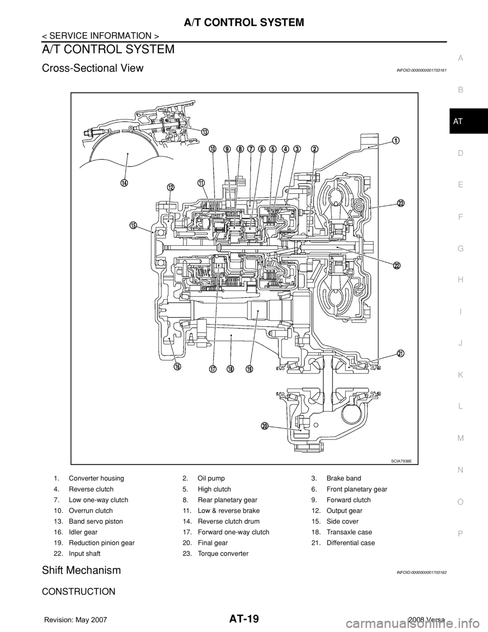
Cross-Sectional ViewINFOID:0000000001703161
Shift MechanismINFOID:0000000001703162
CONSTRUCTION
1. Converter housing 2. Oil pump 3. Brake band
4. Reverse clutch 5. High clutch 6. Front planetary gear
7. Low one-way clutch 8. Rear planetary gear 9. Forward clutch
10. Overrun clutch 11. Low & reverse brake 12. Output gear
13. Band servo piston 14. Reverse clutch drum 15. Side cover
16. Idler gear 17. Forward one-way clutch 18. Transaxle case
19. Reduction pinion gear 20. Final gear 21. Differential case
22. Input shaft 23. Torque converter
SCIA7938E
Page 32 of 2771

AT-20
< SERVICE INFORMATION >
A/T CONTROL SYSTEM
FUNCTION OF CLUTCH AND BRAKE
CLUTCH AND BAND CHART
1. Torque converter 2. Oil pump 3. Input shaft
4. Brake band 5. Reverse clutch 6. High clutch
7. Front sun gear 8. Front pinion gear 9. Front internal gear
10. Front planetary carrier 11. Rear sun gear 12. Rear pinion gear
13. Rear internal gear 14. Rear planetary carrier 15. Forward clutch
16. Forward one-way clutch 17. Overrun clutch 18. Low one-way clutch
19. Low & reverse brake 20. Parking pawl 21. Parking gear
22. Output shaft 23. Idle gear 24. Output gear
SAT998I
Clutch and brake components Abbr. Function
5Reverse clutch R/C To transmit input power to front sun gear 7.
6High clutch H/C To transmit input power to front planetary carrier 10.
15Forward clutch F/C To connect front planetary carrier 10 with forward one-way clutch 16.
17Overrun clutch O/C To connect front planetary carrier 10 with rear internal gear 13.
4Brake band B/B To lock front sun gear 7.
16Forward one-way clutch F/O.CWhen forward clutch 15 is engaged, to stop rear internal gear 13 from rotating in
opposite direction against engine revolution.
18Low one-way clutch L/O.CTo stop front planetary carrier 10 from rotating in opposite direction against en-
gine revolution.
19Low & reverse brake L & R/B To lock front planetary carrier 10.
Shift posi-
tionR/C
5H/C
6F/C
15O/C
17Band servo
F/O.C
16L/O.C
18L&R/B
19Lock-
upRemarks
2nd
apply3rd re-
lease4th ap-
ply
PPA R K
POSITION
RREVERSE
POSITION
NNEUTRAL
POSITION
D*4 1st *1D B B
Page 35 of 2771

A/T CONTROL SYSTEM
AT-23
< SERVICE INFORMATION >
D
E
F
G
H
I
J
K
L
MA
B
AT
N
O
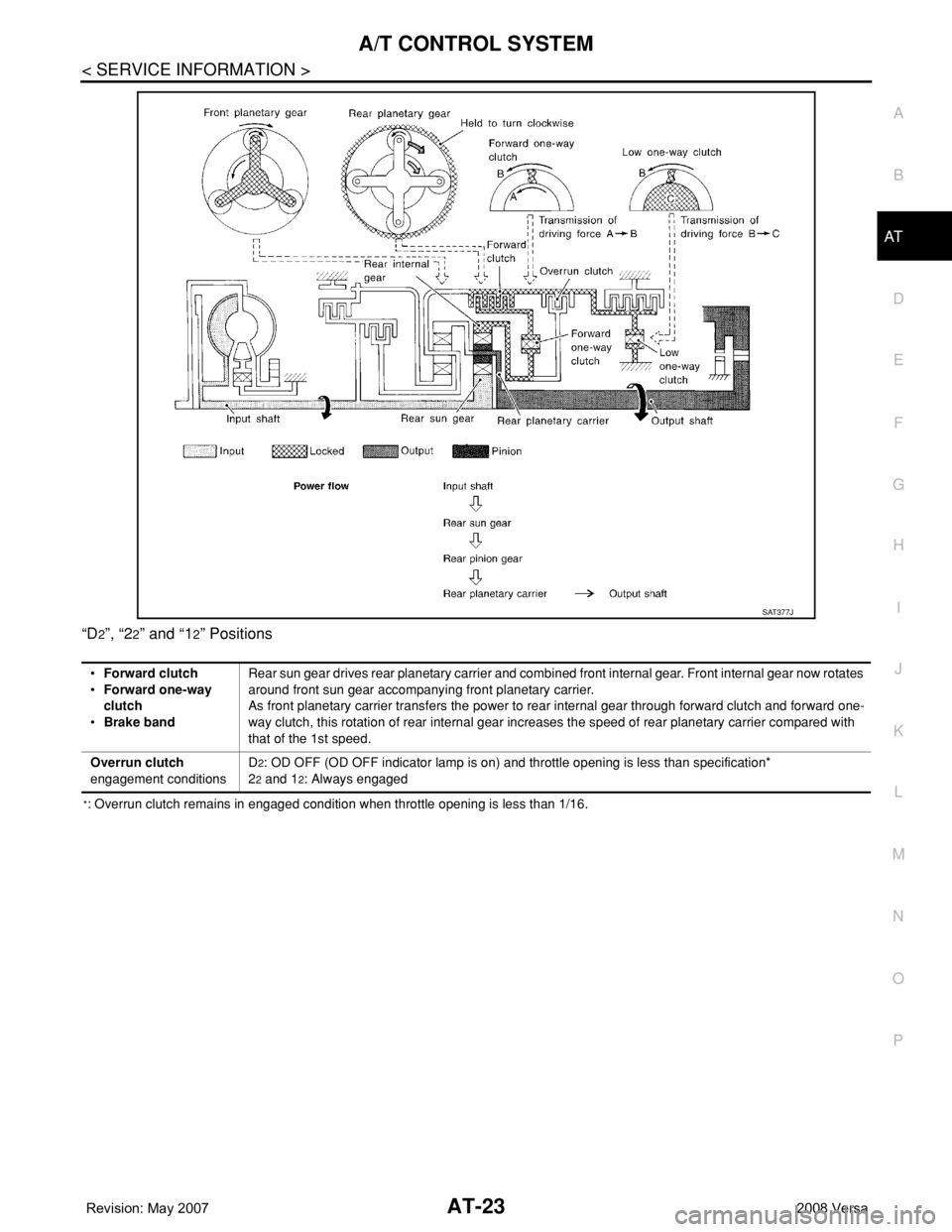
P “D
2”, “22” and “12” Positions
*: Overrun clutch remains in engaged condition when throttle opening is less than 1/16.
SAT377J
•Forward clutch
•Forward one-way
clutch
•Brake bandRear sun gear drives rear planetary carrier and combined front internal gear. Front internal gear now rotates
around front sun gear accompanying front planetary carrier.
As front planetary carrier transfers the power to rear internal gear through forward clutch and forward one-
way clutch, this rotation of rear internal gear increases the speed of rear planetary carrier compared with
that of the 1st speed.
Overrun clutch
engagement conditionsD
2: OD OFF (OD OFF indicator lamp is on) and throttle opening is less than specification*
2
2 and 12: Always engaged
Page 36 of 2771

AT-24
< SERVICE INFORMATION >
A/T CONTROL SYSTEM
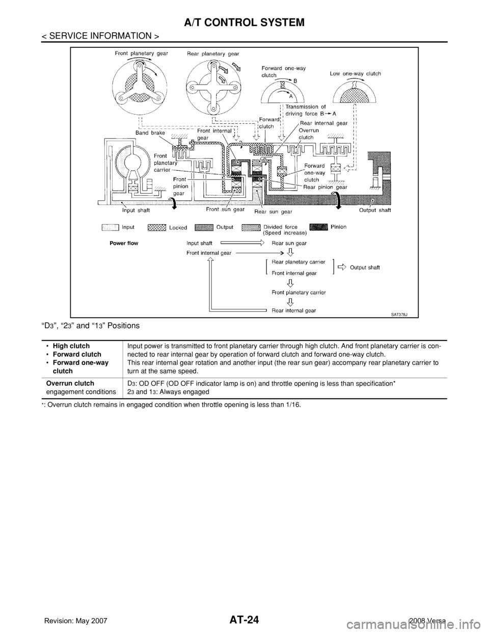
“D3”, “23” and “13” Positions
*: Overrun clutch remains in engaged condition when throttle opening is less than 1/16.
SAT378J
•High clutch
•Forward clutch
•Forward one-way
clutchInput power is transmitted to front planetary carrier through high clutch. And front planetary carrier is con-
nected to rear internal gear by operation of forward clutch and forward one-way clutch.
This rear internal gear rotation and another input (the rear sun gear) accompany rear planetary carrier to
turn at the same speed.
Overrun clutch
engagement conditionsD
3: OD OFF (OD OFF indicator lamp is on) and throttle opening is less than specification*
2
3 and 13: Always engaged
Page 38 of 2771

AT-26
< SERVICE INFORMATION >
A/T CONTROL SYSTEM
“R” Position
SAT380J
•Reverse clutch
•Low & reverse brakeFront planetary carrier is stationary because of the operation of low and reverse brake.
Input power is transmitted to front sun gear through reverse clutch, which drives front
internal gear in the opposite direction.
Engine brakeAs there is no one-way clutch in the power transaxle line, engine brake can be obtained
when decelerating.
Page 40 of 2771

AT-28
< SERVICE INFORMATION >
A/T CONTROL SYSTEM
CONTROL SYSTEM DIAGRAM
CAN CommunicationINFOID:0000000001703164
SYSTEM DESCRIPTION
CAN (Controller Area Network) is a serial communication line for real time application. It is an on-vehicle mul-
tiplex communication line with high data communication speed and excellent error detection ability. Many elec-
tronic control units are equipped onto a vehicle, and each control unit shares information and links with other
control units during operation (not independent). In CAN communication, control units are connected with 2
communication lines (CAN H line, CAN L line) allowing a high rate of information transmission with less wiring.
Each control unit transmits/receives data but selectively reads required data only. For details, refer to LAN-6,
"System Description".
Input/Output Signal of TCMINFOID:0000000001703165
SCIA7112E
Control itemLine
pressure
controlVehicle
speed
controlShift
controlLock-up
controlEngine
brake
controlFail-safe
functionSelf-diag-
nostics
function
InputAccelerator pedal position signal
(*5)XXXXX(*3) XX
Vehicle speed sensor·A/T
(Revolution sensor)XXXXX(*3) XX
Vehicle speed sensor·MTR (*1) X (*1) X (*1) X (*1) X X
Closed throttle position signal
(*5)(*2) X (*2) X X X (*4) X
Wide open throttle position signal
(*5)(*2) X (*2) X (*4) X
Turbine revolution sensor (Power
train revolution sensor)XXXXX
Engine speed signal X X X X
PNP switch XXXXX(*3) X(*4) X
Stop lamp switch signal
(*5)XX (*4) X
A/T fluid temperature sensors
(*5)XXXX XX
Overdrive control switch signal
(*5)XXXX (*4) X
TCM power supply voltage signal X X X X