2008 NISSAN TIIDA stalls
[x] Cancel search: stallsPage 1152 of 2771
EC-78
< SERVICE INFORMATION >
BASIC SERVICE PROCEDURE
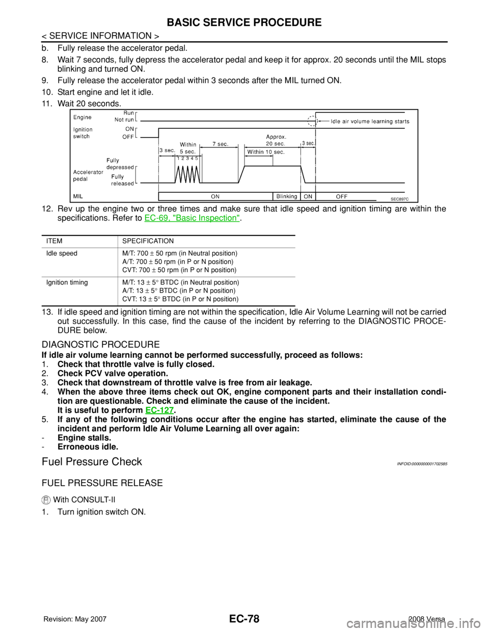
b. Fully release the accelerator pedal.
8. Wait 7 seconds, fully depress the accelerator pedal and keep it for approx. 20 seconds until the MIL stops
blinking and turned ON.
9. Fully release the accelerator pedal within 3 seconds after the MIL turned ON.
10. Start engine and let it idle.
11. Wait 20 seconds.
12. Rev up the engine two or three times and make sure that idle speed and ignition timing are within the
specifications. Refer to EC-69, "
Basic Inspection".
13. If idle speed and ignition timing are not within the specification, Idle Air Volume Learning will not be carried
out successfully. In this case, find the cause of the incident by referring to the DIAGNOSTIC PROCE-
DURE below.
DIAGNOSTIC PROCEDURE
If idle air volume learning cannot be performed successfully, proceed as follows:
1.Check that throttle valve is fully closed.
2.Check PCV valve operation.
3.Check that downstream of throttle valve is free from air leakage.
4.When the above three items check out OK, engine component parts and their installation condi-
tion are questionable. Check and eliminate the cause of the incident.
It is useful to perform EC-127
.
5.If any of the following conditions occur after the engine has started, eliminate the cause of the
incident and perform Idle Air Volume Learning all over again:
-Engine stalls.
-Erroneous idle.
Fuel Pressure CheckINFOID:0000000001702585
FUEL PRESSURE RELEASE
With CONSULT-II
1. Turn ignition switch ON.
ITEM SPECIFICATION
Idle speed M/T: 700 ± 50 rpm (in Neutral position)
A/T: 700 ± 50 rpm (in P or N position)
CVT: 700 ± 50 rpm (in P or N position)
Ignition timing M/T: 13 ± 5° BTDC (in Neutral position)
A/T: 13 ± 5° BTDC (in P or N position)
CVT: 13 ± 5° BTDC (in P or N position)
SEC897C
Page 1153 of 2771
BASIC SERVICE PROCEDURE
EC-79
< SERVICE INFORMATION >
C
D
E
F
G
H
I
J
K
L
MA
EC
N
P O
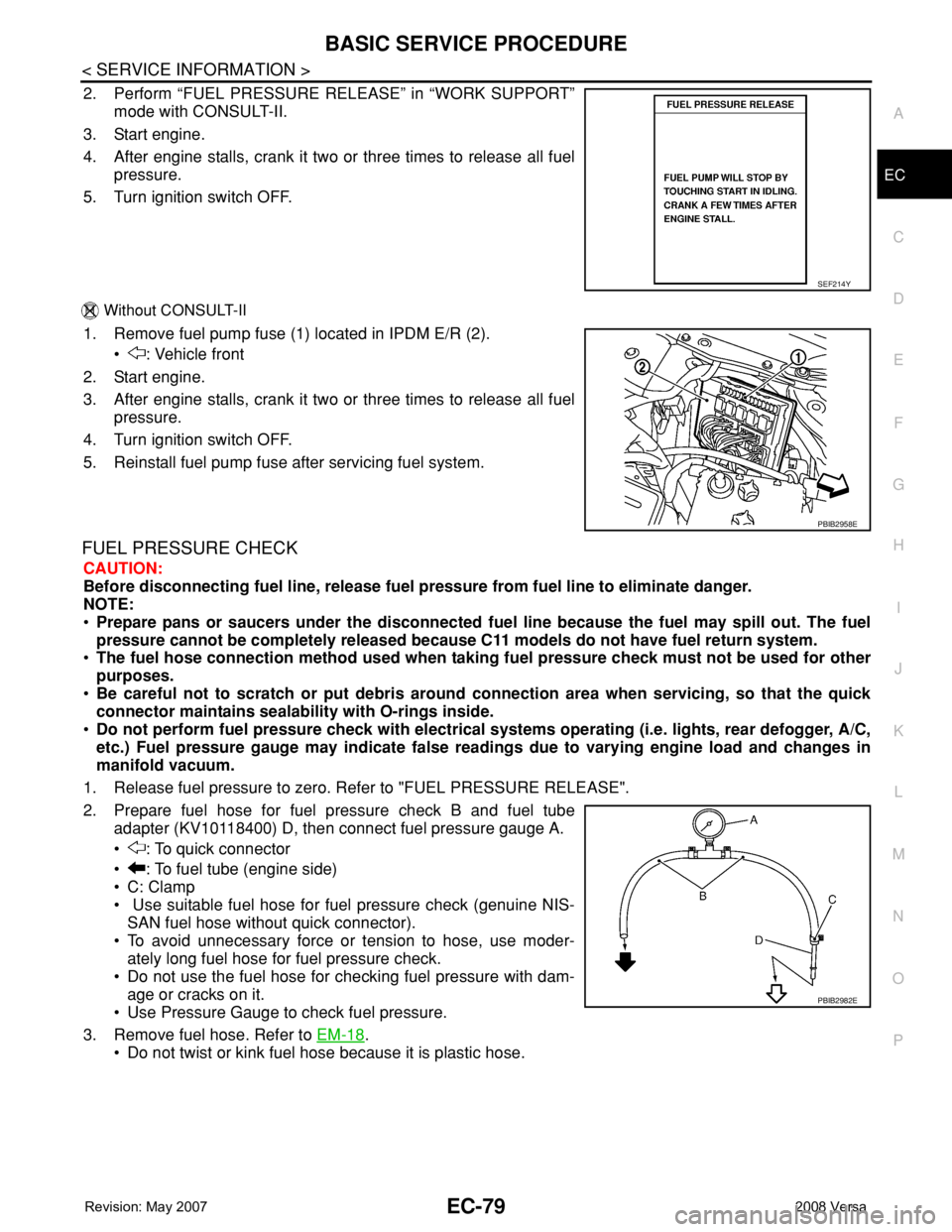
2. Perform “FUEL PRESSURE RELEASE” in “WORK SUPPORT”
mode with CONSULT-II.
3. Start engine.
4. After engine stalls, crank it two or three times to release all fuel
pressure.
5. Turn ignition switch OFF.
Without CONSULT-II
1. Remove fuel pump fuse (1) located in IPDM E/R (2).
• : Vehicle front
2. Start engine.
3. After engine stalls, crank it two or three times to release all fuel
pressure.
4. Turn ignition switch OFF.
5. Reinstall fuel pump fuse after servicing fuel system.
FUEL PRESSURE CHECK
CAUTION:
Before disconnecting fuel line, release fuel pressure from fuel line to eliminate danger.
NOTE:
•Prepare pans or saucers under the disconnected fuel line because the fuel may spill out. The fuel
pressure cannot be completely released because C11 models do not have fuel return system.
•The fuel hose connection method used when taking fuel pressure check must not be used for other
purposes.
•Be careful not to scratch or put debris around connection area when servicing, so that the quick
connector maintains sealability with O-rings inside.
•Do not perform fuel pressure check with electrical systems operating (i.e. lights, rear defogger, A/C,
etc.) Fuel pressure gauge may indicate false readings due to varying engine load and changes in
manifold vacuum.
1. Release fuel pressure to zero. Refer to "FUEL PRESSURE RELEASE".
2. Prepare fuel hose for fuel pressure check B and fuel tube
adapter (KV10118400) D, then connect fuel pressure gauge A.
• : To quick connector
• : To fuel tube (engine side)
• C: Clamp
• Use suitable fuel hose for fuel pressure check (genuine NIS-
SAN fuel hose without quick connector).
• To avoid unnecessary force or tension to hose, use moder-
ately long fuel hose for fuel pressure check.
• Do not use the fuel hose for checking fuel pressure with dam-
age or cracks on it.
• Use Pressure Gauge to check fuel pressure.
3. Remove fuel hose. Refer to EM-18
.
• Do not twist or kink fuel hose because it is plastic hose.
SEF214Y
PBIB2958E
PBIB2982E
Page 1162 of 2771

EC-88
< SERVICE INFORMATION >
TROUBLE DIAGNOSIS
• When there is an open circuit on MIL circuit, the ECM cannot warn the driver by lighting up MIL when there
is malfunction on engine control system.
Therefore, when electrical controlled throttle and part of ECM related diagnoses are continuously detected
as NG for 5 trips, ECM warns the driver that engine control system malfunctions and MIL circuit is open by
means of operating fail-safe function.
The fail-safe function also operates when above diagnoses except MIL circuit are detected and demands the
driver to repair the malfunction.
Symptom Matrix ChartINFOID:0000000001702589
SYSTEM — BASIC ENGINE CONTROL SYSTEM
P0117
P0118Engine coolant temperature
sensor circuitEngine coolant temperature will be determined by ECM based on the time after turning
ignition switch ON or START.
CONSULT-II displays the engine coolant temperature decided by ECM.
ConditionEngine coolant temperature decided
(CONSULT-II display)
Just as ignition switch is turned ON
or START40°C (104°F)
More than approx. 4 minutes after
ignition ON or START80°C (176°F)
Except as shown above40 - 80°C (104 - 176°F)
(Depends on the time)
When the fail-safe system for engine coolant temperature sensor is activated, the cool-
ing fan operates while engine is running.
P0122
P0123
P0222
P0223
P2135Throttle position sensor The ECM controls the electric throttle control actuator in regulating the throttle opening
in order for the idle position to be within +10 degrees.
The ECM regulates the opening speed of the throttle valve to be slower than the normal
condition.
So, the acceleration will be poor.
P0643 Sensor power supply ECM stops the electric throttle control actuator control, throttle valve is maintained at a
fixed opening (approx. 5 degrees) by the return spring.
P2100
P2103Throttle control relay ECM stops the electric throttle control actuator control, throttle valve is maintained at a
fixed opening (approx. 5 degrees) by the return spring.
P2101 Electric throttle control func-
tionECM stops the electric throttle control actuator control, throttle valve is maintained at a
fixed opening (approx. 5 degrees) by the return spring.
P2118 Throttle control motor ECM stops the electric throttle control actuator control, throttle valve is maintained at a
fixed opening (approx. 5 degrees) by the return spring.
P2119 Electric throttle control actu-
ator(When electric throttle control actuator does not function properly due to the return
spring malfunction:)
ECM controls the electric throttle actuator by regulating the throttle opening around the
idle position. The engine speed will not rise more than 2,000 rpm.
(When throttle valve opening angle in fail-safe mode is not in specified range:)
ECM controls the electric throttle control actuator by regulating the throttle opening to
20 degrees or less.
(When ECM detects the throttle valve is stuck open:)
While the vehicle is driving, it slows down gradually by fuel cut. After the vehicle stops,
the engine stalls.
The engine can restart in N or P (A/T, CVT), Neutral (M/T) position, and engine speed
will not exceed 1,000 rpm or more.
P2122
P2123
P2127
P2128
P2138Accelerator pedal position
sensorThe ECM controls the electric throttle control actuator in regulating the throttle opening
in order for the idle position to be within +10 degrees.
The ECM regulates the opening speed of the throttle valve to be slower than the normal
condition.
So, the acceleration will be poor. DTC No. Detected items Engine operating condition in fail-safe mode
Engine operating condition in fail-safe mode Engine speed will not rise more than 2,500 rpm due to the fuel cut
Page 1185 of 2771
TROUBLE DIAGNOSIS
EC-111
< SERVICE INFORMATION >
C
D
E
F
G
H
I
J
K
L
MA
EC
N
P O
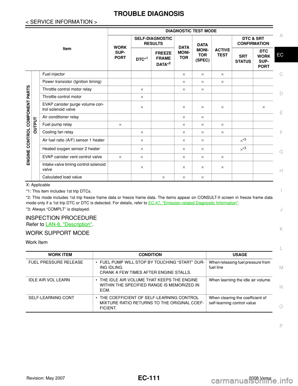
X: Applicable
*1: This item includes 1st trip DTCs.
*2: This mode includes 1st trip freeze frame data or freeze frame data. The items appear on CONSULT-II screen in freeze frame data
mode only if a 1st trip DTC or DTC is detected. For details, refer to EC-47, "
Emission-related Diagnostic Information".
*3: Always “COMPLT” is displayed.
INSPECTION PROCEDURE
Refer to LAN-8, "Description".
WORK SUPPORT MODE
Work Item
ENGINE CONTROL COMPONENT PARTS
OUTPUT
Fuel injector×× ×
Power transistor (Ignition timing)×× ×
Throttle control motor relay×××
Throttle control motor×
EVAP canister purge volume con-
trol solenoid valve×××××
Air conditioner relay××
Fuel pump relay××××
Cooling fan relay××××
Air fuel ratio (A/F) sensor 1 heater×××
×*
3
Heated oxygen sensor 2 heater×××
×*3
EVAP canister vent control valve×× ×××
Intake valve timing control solenoid
valve××××
Calculated load value××× ItemDIAGNOSTIC TEST MODE
WORK
SUP-
PORTSELF-DIAGNOSTIC
RESULTS
DATA
MONI-
TORDATA
MONI-
TOR
(SPEC)ACTIVE
TESTDTC & SRT
CONFIRMATION
DTC*
1 FREEZE
FRAME
DATA*
2
SRT
STATUSDTC
WORK
SUP-
PORT
WORK ITEM CONDITION USAGE
FUEL PRESSURE RELEASE • FUEL PUMP WILL STOP BY TOUCHING “START” DUR-
ING IDLING.
CRANK A FEW TIMES AFTER ENGINE STALLS.When releasing fuel pressure from
fuel line
IDLE AIR VOL LEARN • THE IDLE AIR VOLUME THAT KEEPS THE ENGINE
WITHIN THE SPECIFIED RANGE IS MEMORIZED IN
ECM.When learning the idle air volume
SELF-LEARNING CONT • THE COEFFICIENT OF SELF-LEARNING CONTROL
MIXTURE RATIO RETURNS TO THE ORIGINAL COEF-
FICIENT.When clearing the coefficient of
self-learning control value
Page 1360 of 2771
EC-286
< SERVICE INFORMATION >
DTC P0300 - P0304 MULTIPLE CYLINDER MISFIRE, NO. 1 - 4 CYLINDER MIS-
FIRE
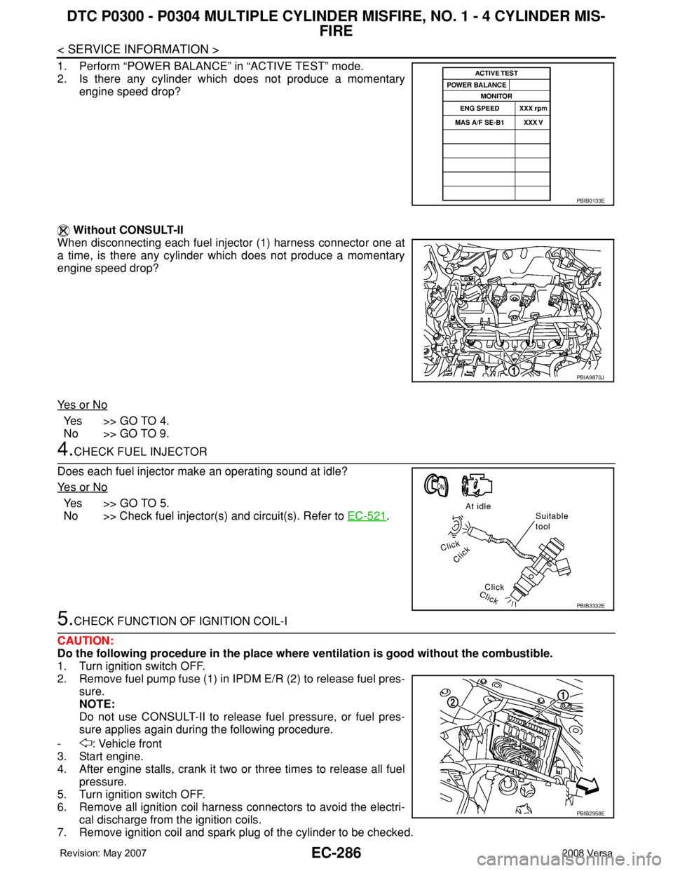
1. Perform “POWER BALANCE” in “ACTIVE TEST” mode.
2. Is there any cylinder which does not produce a momentary
engine speed drop?
Without CONSULT-II
When disconnecting each fuel injector (1) harness connector one at
a time, is there any cylinder which does not produce a momentary
engine speed drop?
Ye s o r N o
Ye s > > G O T O 4 .
No >> GO TO 9.
4.CHECK FUEL INJECTOR
Does each fuel injector make an operating sound at idle?
Ye s o r N o
Ye s > > G O T O 5 .
No >> Check fuel injector(s) and circuit(s). Refer to EC-521
.
5.CHECK FUNCTION OF IGNITION COIL-I
CAUTION:
Do the following procedure in the place where ventilation is good without the combustible.
1. Turn ignition switch OFF.
2. Remove fuel pump fuse (1) in IPDM E/R (2) to release fuel pres-
sure.
NOTE:
Do not use CONSULT-II to release fuel pressure, or fuel pres-
sure applies again during the following procedure.
- : Vehicle front
3. Start engine.
4. After engine stalls, crank it two or three times to release all fuel
pressure.
5. Turn ignition switch OFF.
6. Remove all ignition coil harness connectors to avoid the electri-
cal discharge from the ignition coils.
7. Remove ignition coil and spark plug of the cylinder to be checked.
PBIB0133E
PBIA9870J
PBIB3332E
PBIB2958E
Page 1385 of 2771
DTC P0420 THREE WAY CATALYST FUNCTION
EC-311
< SERVICE INFORMATION >
C
D
E
F
G
H
I
J
K
L
MA
EC
N
P O
OK >> GO TO 6.
NG >> Perform EC-523, "
Diagnosis Procedure".
6.CHECK FUNCTION OF IGNITION COIL-I
CAUTION:
Do the following procedure in the place where ventilation is good without the combustible.
1. Turn ignition switch OFF.
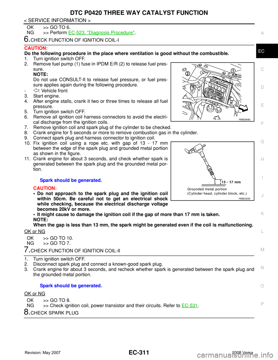
2. Remove fuel pump (1) fuse in IPDM E/R (2) to release fuel pres-
sure.
NOTE:
Do not use CONSULT-II to release fuel pressure, or fuel pres-
sure applies again during the following procedure.
- : Vehicle front
3. Start engine.
4. After engine stalls, crank it two or three times to release all fuel
pressure.
5. Turn ignition switch OFF.
6. Remove all ignition coil harness connectors to avoid the electri-
cal discharge from the ignition coils.
7. Remove ignition coil and spark plug of the cylinder to be checked.
8. Crank engine for 5 seconds or more to remove combustion gas in the cylinder.
9. Connect spark plug and harness connector to ignition coil.
10. Fix ignition coil using a rope etc. with gap of 13 - 17 mm
between the edge of the spark plug and grounded metal portion
as shown in the figure.
11. Crank engine for about 3 seconds, and check whether spark is
generated between the spark plug and the grounded metal por-
tion.
CAUTION:
• Do not approach to the spark plug and the ignition coil
within 50cm. Be careful not to get an electrical shock
while checking, because the electrical discharge voltage
becomes 20kV or more.
• It might cause to damage the ignition coil if the gap of more than 17 mm is taken.
NOTE:
When the gap is less than 13 mm, the spark might be generated even if the coil is malfunctioning.
OK or NG
OK >> GO TO 10.
NG >> GO TO 7.
7.CHECK FUNCTION OF IGNITION COIL-II
1. Turn ignition switch OFF.
2. Disconnect spark plug and connect a known-good spark plug.
3. Crank engine for about 3 seconds, and recheck whether spark is generated between the spark plug and
the grounded metal portion.
OK or NG
OK >> GO TO 8.
NG >> Check ignition coil, power transistor and their circuits. Refer to EC-531
.
8.CHECK SPARK PLUGSpark should be generated.
PBIB2958E
PBIB2325E
Spark should be generated.
Page 1546 of 2771

EC-472
< SERVICE INFORMATION >
DTC P2119 ELECTRIC THROTTLE CONTROL ACTUATOR
DTC P2119 ELECTRIC THROTTLE CONTROL ACTUATOR
Component DescriptionINFOID:0000000001703005
Electric throttle control actuator consists of throttle control motor, throttle position sensor, etc.
The throttle control motor is operated by the ECM and it opens and closes the throttle valve.
The throttle position sensor detects the throttle valve position, and the opening and closing speed of the throt-
tle valve and feeds the voltage signals to the ECM. The ECM judges the current opening angle of the throttle
valve from these signals and the ECM controls the throttle control motor to make the throttle valve opening
angle properly in response to driving condition.
On Board Diagnosis LogicINFOID:0000000001703006
This self-diagnosis has the one trip detection logic.
FAIL-SAFE MODE
When the malfunction is detected, ECM enters fail-safe mode and the MIL lights up.
DTC Confirmation ProcedureINFOID:0000000001703007
NOTE:
•Perform PROCEDURE FOR MALFUNCTION A AND B first. If the DTC cannot be confirmed, perform
PROCEDURE FOR MALFUNCTION C.
• If DTC Confirmation Procedure has been previously conducted, always turn ignition switch OFF and wait at
least 10 seconds before conducting the next test.
PROCEDURE FOR MALFUNCTION A AND B
With CONSULT-II
1. Turn ignition switch ON and wait at least 1 second.
2. Select “DATA MONITOR” mode with CONSULT-II.
3. Set shift lever to D position (A/T, CVT) or 1st position (M/T), and
wait at least 3 seconds.
4. Set shift lever to P position (A/T, CVT) or Neutral position (M/T).
5. Turn ignition switch OFF and wait at least 10 seconds.
6. Turn ignition switch ON and wait at least 1 second.
7. Set shift lever to D position (A/T, CVT) or 1st position (M/T), and
wait at least 3 seconds.
8. Set shift lever to P position (A/T, CVT) or Neutral position (M/T).
9. Turn ignition switch OFF, wait at least 10 seconds, and then turn
ON.
DTC No. Trouble diagnosis name DTC detecting condition Possible cause
P2119
2119Electric throttle control
actuatorA)Electric throttle control actuator does not func-
tion properly due to the return spring malfunc-
tion.
• Electric throttle control actuator
B)Throttle valve opening angle in fail-safe mode is
not in specified range.
C) ECM detects the throttle valve is stuck open.
Detected items Engine operating condition in fail-safe mode
Malfunction AECM controls the electric throttle actuator by regulating the throttle opening around the idle position. The
engine speed will not rise more than 2,000 rpm.
Malfunction B ECM controls the electric throttle control actuator by regulating the throttle opening to 20 degrees or less.
Malfunction CWhile the vehicle is driving, it slows down gradually by fuel cut. After the vehicle stops, the engine stalls.
The engine can restart in N or P position (A/T, CVT), neutral (M/T), and engine speed will not exceed 1,000
rpm or more.
SEF058Y
Page 1600 of 2771
EC-526
< SERVICE INFORMATION >
FUEL PUMP
FUEL PUMP
DescriptionINFOID:0000000001703065
SYSTEM DESCRIPTION
*: ECM determines the start signal status by the signals of engine speed and battery voltage.
The ECM activates the fuel pump for several seconds after the ignition switch is turned ON to improve engine
startability. If the ECM receives a engine speed signal from the crankshaft position sensor (POS) and cam-
shaft position sensor (PHASE), it knows that the engine is rotating, and causes the pump to operate. If the
engine speed signal is not received when the ignition switch is ON, the engine stalls. The ECM stops pump
operation and prevents battery discharging, thereby improving safety. The ECM does not directly drive the fuel
pump. It controls the ON/OFF fuel pump relay, which in turn controls the fuel pump.
COMPONENT DESCRIPTION
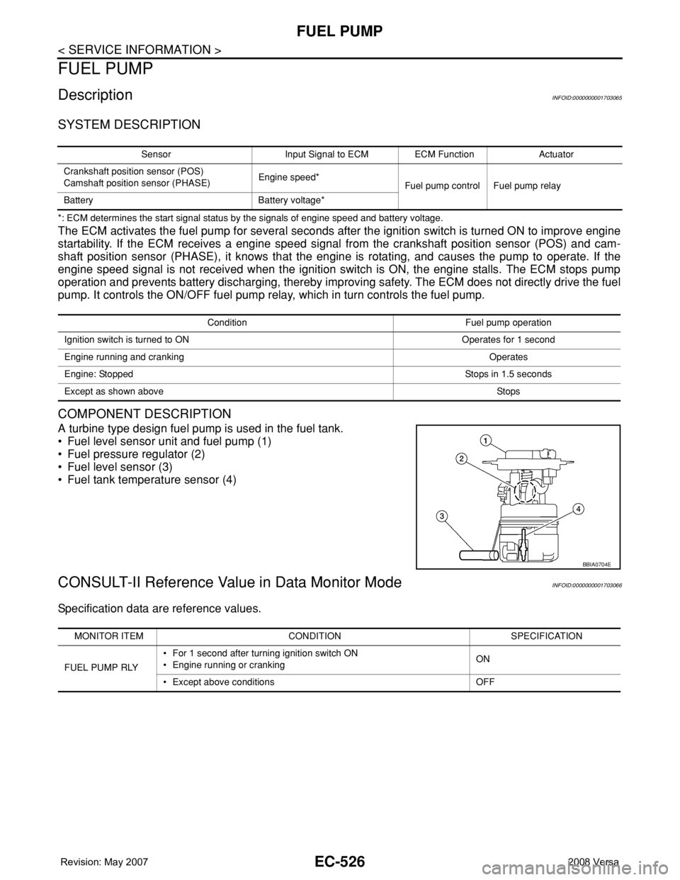
A turbine type design fuel pump is used in the fuel tank.
• Fuel level sensor unit and fuel pump (1)
• Fuel pressure regulator (2)
• Fuel level sensor (3)
• Fuel tank temperature sensor (4)
CONSULT-II Reference Value in Data Monitor ModeINFOID:0000000001703066
Specification data are reference values.
Sensor Input Signal to ECM ECM Function Actuator
Crankshaft position sensor (POS)
Camshaft position sensor (PHASE)Engine speed*
Fuel pump control Fuel pump relay
Battery Battery voltage*
Condition Fuel pump operation
Ignition switch is turned to ON Operates for 1 second
Engine running and crankingOperates
Engine: StoppedStops in 1.5 seconds
Except as shown aboveSt ops
BBIA0704E
MONITOR ITEM CONDITION SPECIFICATION
FUEL PUMP RLY• For 1 second after turning ignition switch ON
• Engine running or crankingON
• Except above conditions OFF