2008 NISSAN TIIDA lan system
[x] Cancel search: lan systemPage 45 of 2771

A/T CONTROL SYSTEM
AT-33
< SERVICE INFORMATION >
D
E
F
G
H
I
J
K
L
MA
B
AT
N
O
P
OVERRUN CLUTCH OPERATING CONDITIONS
OVERRUN CLUTCH SOLENOID VALVE CONTROL
The overrun clutch solenoid valve is operated by an ON-OFF signal
transmitted by the TCM to provide overrun clutch control (engine
brake control).
When this solenoid valve is “ON”, the pilot pressure drain port
closes. When it is “OFF”, the drain port opens.
During the solenoid valve “ON” pilot pressure is applied to the end
face of the overrun clutch control valve.
OVERRUN CLUTCH CONTROL VALVE OPERATION
When the solenoid valve is “ON”, pilot pressure is applied to the
overrun clutch control valve. This pushes up the overrun clutch con-
trol valve. The line pressure is then shut off so that the clutch does
not engage. Only in “1” position, however, 1 range pressure is
applied to overrun clutch control valve, resulting in valve moving
downward and clutch engaged.
When the solenoid valve is “OFF”, pilot pressure is not generated. At
this point, the overrun clutch control valve moves downward by
spring force. As a result, overrun clutch operation pressure is pro-
vided by the overrun clutch reducing valve. At overrun clutch reduc-
ing valve in “D” position, the hydraulic pressure is reduced to a level
that balances the spring force. This is sent to overrun clutch control
valve and becomes the operating pressure of overrun clutch which is
engaged at all times. In “2” position and “1” position, overrun clutch
reducing valve is pushed down by 2 range pressure. Line pressure is
directly sent to overrun clutch control valve and becomes the operat-
ing pressure of overrun clutch which is engaged at all times.
SCIA7186E
SAT015J
SCIA7172E
Page 48 of 2771
AT-36
< SERVICE INFORMATION >
ON BOARD DIAGNOSTIC (OBD) SYSTEM
ON BOARD DIAGNOSTIC (OBD) SYSTEM
IntroductionINFOID:0000000001703172
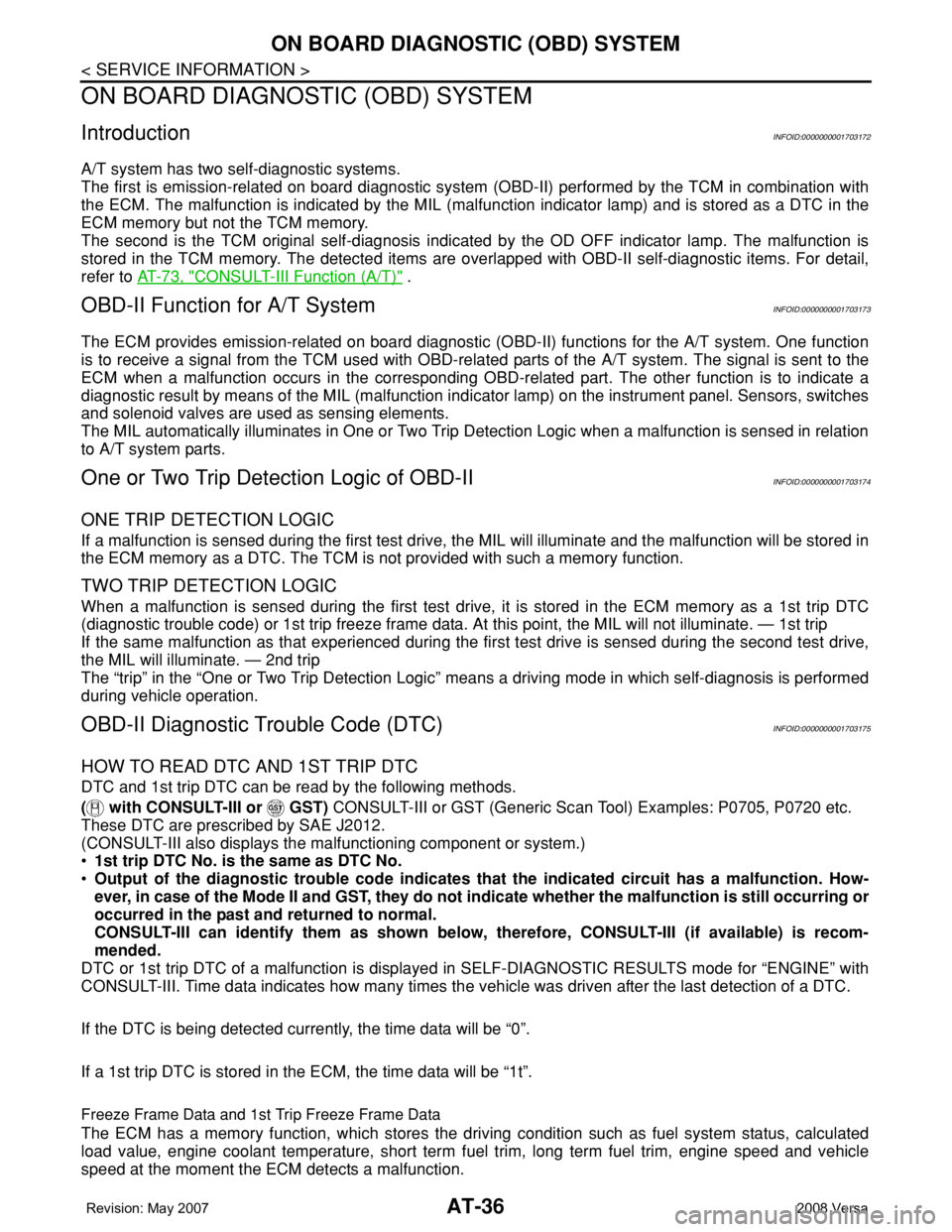
A/T system has two self-diagnostic systems.
The first is emission-related on board diagnostic system (OBD-II) performed by the TCM in combination with
the ECM. The malfunction is indicated by the MIL (malfunction indicator lamp) and is stored as a DTC in the
ECM memory but not the TCM memory.
The second is the TCM original self-diagnosis indicated by the OD OFF indicator lamp. The malfunction is
stored in the TCM memory. The detected items are overlapped with OBD-II self-diagnostic items. For detail,
refer to AT-73, "
CONSULT-III Function (A/T)" .
OBD-II Function for A/T SystemINFOID:0000000001703173
The ECM provides emission-related on board diagnostic (OBD-II) functions for the A/T system. One function
is to receive a signal from the TCM used with OBD-related parts of the A/T system. The signal is sent to the
ECM when a malfunction occurs in the corresponding OBD-related part. The other function is to indicate a
diagnostic result by means of the MIL (malfunction indicator lamp) on the instrument panel. Sensors, switches
and solenoid valves are used as sensing elements.
The MIL automatically illuminates in One or Two Trip Detection Logic when a malfunction is sensed in relation
to A/T system parts.
One or Two Trip Detection Logic of OBD-IIINFOID:0000000001703174
ONE TRIP DETECTION LOGIC
If a malfunction is sensed during the first test drive, the MIL will illuminate and the malfunction will be stored in
the ECM memory as a DTC. The TCM is not provided with such a memory function.
TWO TRIP DETECTION LOGIC
When a malfunction is sensed during the first test drive, it is stored in the ECM memory as a 1st trip DTC
(diagnostic trouble code) or 1st trip freeze frame data. At this point, the MIL will not illuminate. — 1st trip
If the same malfunction as that experienced during the first test drive is sensed during the second test drive,
the MIL will illuminate. — 2nd trip
The “trip” in the “One or Two Trip Detection Logic” means a driving mode in which self-diagnosis is performed
during vehicle operation.
OBD-II Diagnostic Trouble Code (DTC)INFOID:0000000001703175
HOW TO READ DTC AND 1ST TRIP DTC
DTC and 1st trip DTC can be read by the following methods.
( with CONSULT-III or GST) CONSULT-III or GST (Generic Scan Tool) Examples: P0705, P0720 etc.
These DTC are prescribed by SAE J2012.
(CONSULT-III also displays the malfunctioning component or system.)
•1st trip DTC No. is the same as DTC No.
•Output of the diagnostic trouble code indicates that the indicated circuit has a malfunction. How-
ever, in case of the Mode II and GST, they do not indicate whether the malfunction is still occurring or
occurred in the past and returned to normal.
CONSULT-III can identify them as shown below, therefore, CONSULT-III (if available) is recom-
mended.
DTC or 1st trip DTC of a malfunction is displayed in SELF-DIAGNOSTIC RESULTS mode for “ENGINE” with
CONSULT-III. Time data indicates how many times the vehicle was driven after the last detection of a DTC.
If the DTC is being detected currently, the time data will be “0”.
If a 1st trip DTC is stored in the ECM, the time data will be “1t”.
Freeze Frame Data and 1st Trip Freeze Frame Data
The ECM has a memory function, which stores the driving condition such as fuel system status, calculated
load value, engine coolant temperature, short term fuel trim, long term fuel trim, engine speed and vehicle
speed at the moment the ECM detects a malfunction.
Page 97 of 2771
DTC U1000 CAN COMMUNICATION LINE
AT-85
< SERVICE INFORMATION >
D
E
F
G
H
I
J
K
L
MA
B
AT
N
O
P
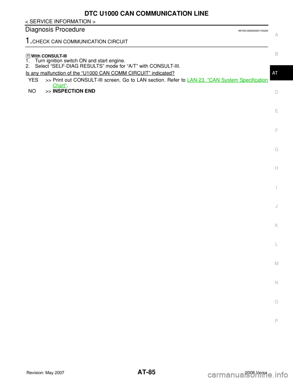
Diagnosis ProcedureINFOID:0000000001703200
1.CHECK CAN COMMUNICATION CIRCUIT
With CONSULT-III1. Turn ignition switch ON and start engine.
2. Select “SELF-DIAG RESULTS” mode for “A/T” with CONSULT-III.
Is any malfunction of the
“U1000 CAN COMM CIRCUIT” indicated?
YES >> Print out CONSULT-III screen, Go to LAN section. Refer to LAN-23, "CAN System Specification
Chart".
NO >>INSPECTION END
Page 423 of 2771

BCM (BODY CONTROL MODULE)
BCS-7
< SERVICE INFORMATION >
C
D
E
F
G
H
I
J
L
MA
B
BCS
N
O
P
CAN Communication System DescriptionINFOID:0000000001704585
Refer to LAN-6, "System Description".
Panic alarm• Key switch
•KeyfobIPDM E/R
Vehicle security system• All door switches
•Keyfob
• Door lock/unlock switch
• Trunk key cylinder switch (Se-
dan)
• Front door key cylinder switch
LH• IPDM/ER
• Security indicator lamp
Battery saver control• Ignition switch
• Combination switchIPDM E/R
Headlamp Combination switch IPDM E/R
Tail lamp Combination switch IPDM E/R
Front fog lamp Combination switch IPDM E/R
Turn signal lamp Combination switch• Turn signal lamp
• Combination meter
Hazard lamp Hazard switch• Turn signal lamp
• Combination meter
Room lamp timer• Key switch
•Keyfob
• Main power window and door
lock/unlock switch
• Front door switch LH
• All door switchInterior room lamp
Back door switch signal (Hatchback) Back door lock assembly Luggage room lamp
Back door lock signal (Hatchback) Back door lock assembly Back door opener
Trunk lamp switch signalTrunk lamp switch and trunk re-
lease solenoidLuggage room lamp
Trunk lid opener signalTrunk lamp switch and trunk re-
lease solenoidTrunk lid opener
Key warning chime• Key switch
• Front door switch LHCombination meter (warning buzzer)
Light warning chime• Combination switch
• Key switch
• Front door switch LHCombination meter (warning buzzer)
Seat belt warning chime• Seat belt buckle switch LH
• Ignition switchCombination meter (warning buzzer)
Front wiper and washer system• Combination switch
• Ignition switchIPDM E/R
Rear window defogger Rear window defogger switch IPDM E/R
Rear wiper and washer system• Combination switch
• Ignition switchRear wiper motor
A/C switch signal Front air control ECM
Blower fan switch signal Front air control ECM
A/C indicator signal Front air control A/C indicator
Low tire pressure warning system Remote keyless entry receiver Combination meterSystem Input Output
Page 433 of 2771
BCM (BODY CONTROL MODULE)
BCS-17
< SERVICE INFORMATION >
C
D
E
F
G
H
I
J
L
MA
B
BCS
N
O
P
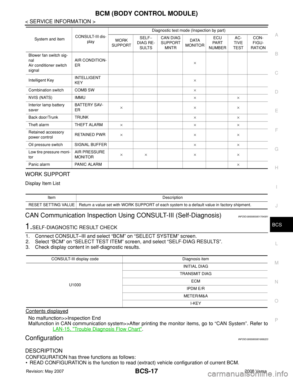
WORK SUPPORT
Display Item List
CAN Communication Inspection Using CONSULT-III (Self-Diagnosis)INFOID:0000000001704591
1.SELF-DIAGNOSTIC RESULT CHECK
1. Connect CONSULT–III and select “BCM” on “SELECT SYSTEM” screen.
2. Select “BCM” on “SELECT TEST ITEM” screen, and select “SELF-DIAG RESULTS”.
3. Check display content in self-diagnostic results.
Contents displayed
No malfunction>>Inspection End
Malfunction in CAN communication system>>After printing the monitor items, go to “CAN System”. Refer to
LAN-15, "
Trouble Diagnosis Flow Chart".
ConfigurationINFOID:0000000001806223
DESCRIPTION
CONFIGURATION has three functions as follows:
• READ CONFIGURATION is the function to read (extract) vehicle configuration of current BCM.
Blower fan switch sig-
nal
Air conditioner switch
signalAIR CONDITION-
ER×
Intelligent KeyINTELLIGENT
KEY×
Combination switch COMB SW×
NVIS (NATS) IMMU××
Interior lamp battery
saverBATTERY SAV-
ER×××
Back door/Trunk TRUNK××
Theft alarm THEFT ALARM×××
Retained accessory
power controlRETAINED PWR×××
Oil pressure switch SIGNAL BUFFER××
Low tire pressure moni-
torAIR PRESSURE
MONITOR×× × ×
Panic alarm PANIC ALARM× System and itemCONSULT-III dis-
playDiagnostic test mode (Inspection by part)
WORK
SUPPORTSELF−
DIAG RE-
SULTSCAN DIAG
SUPPORT
MNTRDATA
MONITORECU
PA R T
NUMBERAC-
TIVE
TESTCON-
FIGU-
RATION
Item Description
RESET SETTING VALUE Return a value set with WORK SUPPORT of each system to a default value in factory shipment.
CONSULT-III display code Diagnosis item
U1000INITIAL DIAG
TRANSMIT DIAG
ECM
IPDM E/R
METER/M&A
I-KEY
Page 458 of 2771

BL-24
< SERVICE INFORMATION >
POWER DOOR LOCK SYSTEM
OUTLINE
Functions available by operating the inside door lock and unlock switches
• Interlocked with the locking operation of door lock and unlock switch, door lock actuators of all doors are
locked.
• Interlocked with the unlocking operation of door lock and unlock switch, door lock actuators of all doors are
unlocked.
Functions available by operating the front door key cylinder switch LH
• Interlocked with the locking operation of front door key cylinder switch LH, door lock actuators of all doors
are locked.
• When front door key cylinder switch LH is unlocked, front door lock actuator LH is unlocked.
• When front door key cylinder switch LH is unlocked for the second time within 5 seconds after the first oper-
ation, door lock actuators on all doors are unlocked.
Key reminder door system
When door lock and unlock switch is operated to lock doors with ignition key inserted in key cylinder and any
door open, all door lock actuators are locked and then unlocked.
CAN Communication System DescriptionINFOID:0000000001703955
Refer to LAN-6 .
Page 487 of 2771
REMOTE KEYLESS ENTRY SYSTEM
BL-53
< SERVICE INFORMATION >
C
D
E
F
G
H
J
K
L
MA
B
BL
N
O
P
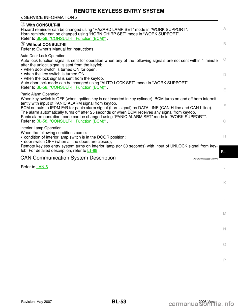
With CONSULT-III
Hazard reminder can be changed using “HAZARD LAMP SET” mode in “WORK SUPPORT”.
Horn reminder can be changed using “HORN CHIRP SET” mode in “WORK SUPPORT”.
Refer to BL-58, "
CONSULT-III Function (BCM)" .
Without CONSULT-III
Refer to Owner's Manual for instructions.
Auto Door Lock Operation
Auto lock function signal is sent for operation when any of the following signals are not sent within 1 minute
after the unlock signal is sent from the keyfob:
• when door switch is turned ON for open.
• when the key switch is turned ON.
• when the lock signal is sent from the keyfob.
Auto door lock mode can be changed using “AUTO LOCK SET” mode in “WORK SUPPORT”.
Refer to BL-58, "
CONSULT-III Function (BCM)" .
Panic Alarm Operation
When key switch is OFF (when ignition key is not inserted in key cylinder), BCM turns on and off horn intermit-
tently with input of PANIC ALARM signal from keyfob.
BCM outputs to IPDM E/R for panic alarm signal (horn signal) as DATA LINE (CAN H line and CAN L line).
The alarm automatically turns off after 25 seconds or when BCM receives any signal from keyfob.
Panic alarm operation mode can be changed using “PANIC ALARM SET” mode in “WORK SUPPORT”.
Refer to BL-58, "
CONSULT-III Function (BCM)" .
Interior Lamp Operation
When the following conditions come:
• condition of interior lamp switch is in the DOOR position;
• door switch OFF (when all the doors are closed);
Remote keyless entry system turns on interior lamp (for 30 seconds) with input of UNLOCK signal from key-
fob. For detailed description, refer to LT- 8 9
.
CAN Communication System DescriptionINFOID:0000000001703975
Refer to LAN-6 .
Page 517 of 2771
INTELLIGENT KEY SYSTEM
BL-83
< SERVICE INFORMATION >
C
D
E
F
G
H
J
K
L
MA
B
BL
N
O
P
CHANGE SETTINGS FUNCTION
The settings for each function can be changed with the CONSULT-III.
Changing Settings Using CONSULT-III
The settings for the Intelligent Key system functions can be changed using CONSULT-III (WORK SUPPORT).
Refer to BL-101, "
CONSULT-III Application Item".
NOTE:
Once a function setting is changed, it will remain effective even if the battery is disconnected.
INTELLIGENT KEY REGISTRATION
Intelligent Key-ID registration is performed using the CONSULT-III.
CAUTION:
• After a new Intelligent Key-ID is registered, be sure to check the function.
• When registering an additional Intelligent Key-ID, take any Intelligent Keys already registered and
Intelligent Keys for any other vehicles out of the vehicle before starting.
CONSULT-III can be used to check and delete Intelligent Key-IDs.
For further information, see the CONSULT-III Operation Manual NATS.
STEERING LOCK SOLENOID REGISTRATION
Steering Lock Solenoid ID Registration
CAUTION:
• The method for registering a steering lock solenoid ID depends on the status of the steering lock
solenoid and Intelligent Key unit (new or old unit).
• After registration is completed, press ignition switch with an Intelligent Key in the vehicle so that it
can be turned, and confirm that it cannot be turned even when ignition switch is pressed without an
Intelligent Key in the vehicle.
For further information, see the CONSULT-III Operation Manual NATS-IVIS/NVIS.
CAN Communication System DescriptionINFOID:0000000001704000
Refer to LAN-6.
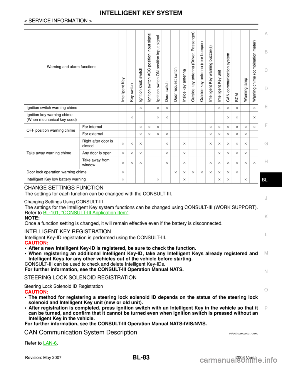
Warning and alarm functions
Intelligent Key
Key switch
Ignition knob switch
Ignition switch ACC position input signal
Ignition switch ON position input signal
Door switch
Door request switch
Inside key antenna
Outside key antenna (Driver, Passenger)
Outside key antenna (rear bumper)
Intelligent Key warning buzzer(s)
Intelligent Key unit
CAN communication system
BCM
Warning lamp
Warning chime (combination meter)
Ignition switch warning chime× ×× ××× ×
Ignition key warning chime
(When mechanical key used)××× ×××
OFF position warning chimeFor internal××× ××××××
For external×××× ×××××
Take away warning chimeRight after door is
closed××× × × ×××××
Any door is open××× × × ××××
Take away from
window××× × × ××××××
Door lock operation warning chime× ××××××××
Intelligent Key low battery warning××××××