2008 NISSAN TIIDA wheels
[x] Cancel search: wheelsPage 1 of 2771

-1
QUICK REFERENCE INDEX
AGENERAL INFORMATIONGIGeneral Information
BENGINEEMEngine Mechanical
LUEngine Lubrication System
COEngine Cooling System
ECEngine Control System
FLFuel System
EXExhaust System
ACCAccelerator Control System
CTRANSMISSION/
TRANSAXLECLClutch System
MTManual Transaxle
ATAutomatic Transaxle
CVTCVT
DDRIVELINE/AXLEFAXFront Axle
RAXRear Axle
ESUSPENSIONFSUFront Suspension
RSURear Suspension
WTRoad Wheels & Tires
FBRAKESBRBrake System
PBParking Brake System
BRCBrake Control System
GSTEERINGPSPower Steering System
STCSteering Control System
HRESTRAINTSSBSeat Belts
SRSSupplemental Restraint System (SRS)
IBODYBLBody, Lock & Security System
GWGlasses, Window System & Mirrors
RFRoof
EIExterior & Interior
IPInstrument Panel
SESeat
JAIR CONDITIONERMTCManual Air Conditioner
KELECTRICALSCStarting & Charging System
LTLighting System
DIDriver Information System
WWWiper, Washer & Horn
BCSBody Control System
LANLAN System
AVAudio Visual, Navigation & Telephone System
ACSAuto Cruise Control System
PGPower Supply, Ground & Circuit Elements
LMAINTENANCEMAMaintenance
Edition: May 2007
Revision: May 2007
Publication No. SM8E-1C11U0
B
D
© 2007 NISSAN NORTH AMERICA, INC.
All rights reserved. No part of this Service Manual may be reproduced or stored in a retrieval system, or transmitted in any
form, or by any means, electronic, mechanical, photo-copying, recording or otherwise, without the prior written permission
of Nissan North America Inc.
A
C
E
F
G
H
I
J
K
L
M
Page 44 of 2771

AT-32
< SERVICE INFORMATION >
A/T CONTROL SYSTEM
Lock-up Control System Diagram
Lock-up Released
In the lock-up released state, the torque converter clutch control valve is set into the unlocked state by drain-
ing the torque converter clutch piston applying pressure and the torque converter clutch piston release pres-
sure is generated.
In this way, the torque converter clutch piston is not coupled.
Lock-up Applied
In the lock-up applied state, the torque converter clutch control valve is set into the locked state by generating
the torque converter clutch piston applying pressure and the torque converter clutch piston release pressure is
drained.
In this way, the torque converter clutch piston is pressed and coupled.
SMOOTH LOCK-UP CONTROL
When shifting from the lock-up released state to the lock-up applied state, the current output to the torque con-
verter clutch solenoid is controlled with the TCM. In this way, when shifting to the lock-up applied state, the
torque converter clutch is temporarily set to the half-clutched state to reduce the shock.
Half-clutched State
The current output from the TCM to the torque converter clutch solenoid is varied to steadily increase the
torque converter clutch solenoid pressure.
In this way, the lock-up applying pressure gradually rises and while the torque converter clutch piston is put
into half-clutched status, the torque converter clutch piston applying pressure is increased and the coupling is
completed smoothly.
Engine Brake Control (Overrun Clutch Control)INFOID:0000000001703169
Forward one-way clutch is used to reduce shifting shocks in downshifting operations. This clutch transmits
engine torque to the wheels. However, drive force from the wheels is not transmitted to the engine because
the one-way clutch rotates idle. This means the engine brake is not effective.
The overrun clutch operates when the engine brake is needed.
SCIA5623E
Page 60 of 2771

AT-48
< SERVICE INFORMATION >
TROUBLE DIAGNOSIS
Inspections Before Trouble Diagnosis
INFOID:0000000001703182
A/T FLUID CHECK
Fluid Leakage and Fluid Level Check
Check fluid leakage and check the fluid level. Refer to MA-22, "Checking A/T Fluid".
Fluid Condition Check
Check the A/T fluid condition.
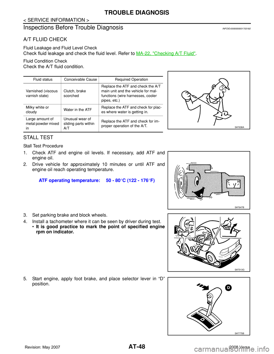
STALL TEST
Stall Test Procedure
1. Check ATF and engine oil levels. If necessary, add ATF and
engine oil.
2. Drive vehicle for approximately 10 minutes or until ATF and
engine oil reach operating temperature.
3. Set parking brake and block wheels.
4. Install a tachometer where it can be seen by driver during test.
•It is good practice to mark the point of specified engine
rpm on indicator.
5. Start engine, apply foot brake, and place selector lever in “D”
position.
Fluid status Conceivable Cause Required Operation
Varnished (viscous
varnish state)Clutch, brake
scorchedReplace the ATF and check the A/T
main unit and the vehicle for mal-
functions (wire harnesses, cooler
pipes, etc.)
Milky white or
cloudyWater in the ATFReplace the ATF and check for plac-
es where water is getting in.
Large amount of
metal powder mixed
inUnusual wear of
sliding parts within
A/TReplace the ATF and check for im-
proper operation of the A/T.
SAT638A
ATF operating temperature: 50 - 80°C (122 - 176°F)
SAT647B
SAT513G
SAT775B
Page 63 of 2771

TROUBLE DIAGNOSIS
AT-51
< SERVICE INFORMATION >
D
E
F
G
H
I
J
K
L
MA
B
AT
N
O
P
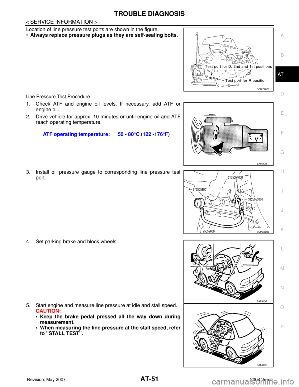
Location of line pressure test ports are shown in the figure.
•Always replace pressure plugs as they are self-sealing bolts.
Line Pressure Test Procedure
1. Check ATF and engine oil levels. If necessary, add ATF or
engine oil.
2. Drive vehicle for approx. 10 minutes or until engine oil and ATF
reach operating temperature.
3. Install oil pressure gauge to corresponding line pressure test
port.
4. Set parking brake and block wheels.
5. Start engine and measure line pressure at idle and stall speed.
CAUTION:
• Keep the brake pedal pressed all the way down during
measurement.
• When measuring the line pressure at the stall speed, refer
to "STALL TEST".
SCIA7187E
ATF operating temperature: 50 - 80°C (122 -176°F)
SAT647B
SCIA6528J
SAT513G
SAT493G
Page 758 of 2771

FRONT DISC BRAKE
BR-27
< SERVICE INFORMATION >
C
D
E
G
H
I
J
K
L
MA
B
BR
N
O
P
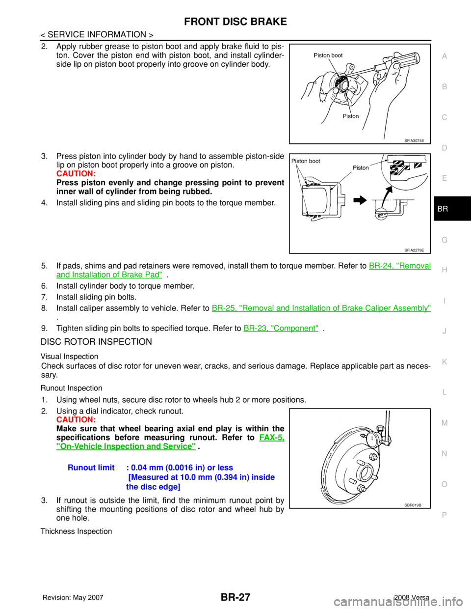
2. Apply rubber grease to piston boot and apply brake fluid to pis-
ton. Cover the piston end with piston boot, and install cylinder-
side lip on piston boot properly into groove on cylinder body.
3. Press piston into cylinder body by hand to assemble piston-side
lip on piston boot properly into a groove on piston.
CAUTION:
Press piston evenly and change pressing point to prevent
inner wall of cylinder from being rubbed.
4. Install sliding pins and sliding pin boots to the torque member.
5. If pads, shims and pad retainers were removed, install them to torque member. Refer to BR-24, "
Removal
and Installation of Brake Pad" .
6. Install cylinder body to torque member.
7. Install sliding pin bolts.
8. Install caliper assembly to vehicle. Refer to BR-25, "
Removal and Installation of Brake Caliper Assembly"
.
9. Tighten sliding pin bolts to specified torque. Refer to BR-23, "
Component" .
DISC ROTOR INSPECTION
Visual Inspection
Check surfaces of disc rotor for uneven wear, cracks, and serious damage. Replace applicable part as neces-
sary.
Runout Inspection
1. Using wheel nuts, secure disc rotor to wheels hub 2 or more positions.
2. Using a dial indicator, check runout.
CAUTION:
Make sure that wheel bearing axial end play is within the
specifications before measuring runout. Refer to FA X - 5 ,
"On-Vehicle Inspection and Service" .
3. If runout is outside the limit, find the minimum runout point by
shifting the mounting positions of disc rotor and wheel hub by
one hole.
Thickness Inspection
SFIA3074E
SFIA2279E
Runout limit : 0.04 mm (0.0016 in) or less
[Measured at 10.0 mm (0.394 in) inside
the disc edge]
SBR019B
Page 770 of 2771
![NISSAN TIIDA 2008 Service Repair Manual SYSTEM DESCRIPTION
BRC-5
< SERVICE INFORMATION >[ABS]
C
D
E
G
H
I
J
K
L
MA
B
BRC
N
O
P
SYSTEM DESCRIPTION
System ComponentINFOID:0000000001703825
ABS FunctionINFOID:0000000001703826
• The Anti-Lock NISSAN TIIDA 2008 Service Repair Manual SYSTEM DESCRIPTION
BRC-5
< SERVICE INFORMATION >[ABS]
C
D
E
G
H
I
J
K
L
MA
B
BRC
N
O
P
SYSTEM DESCRIPTION
System ComponentINFOID:0000000001703825
ABS FunctionINFOID:0000000001703826
• The Anti-Lock](/manual-img/5/57399/w960_57399-769.png)
SYSTEM DESCRIPTION
BRC-5
< SERVICE INFORMATION >[ABS]
C
D
E
G
H
I
J
K
L
MA
B
BRC
N
O
P
SYSTEM DESCRIPTION
System ComponentINFOID:0000000001703825
ABS FunctionINFOID:0000000001703826
• The Anti-Lock Brake System detects wheel revolution while braking and improves handling stability during
sudden braking by electrically preventing wheel lockup. Maneuverability is also improved for avoiding obsta-
cles during emergency braking.
• If the electrical system malfunctions, the Fail-Safe function is activated, the ABS becomes inoperative and
the ABS warning lamp turns on.
• The electrical system can be diagnosed using CONSULT-III.
• During ABS operation, the brake pedal may vibrate lightly and a mechanical noise may be heard. This is
normal.
• Just after starting the vehicle, the brake pedal may vibrate or motor operating noises may be heard from the
engine compartment. This is normal due to the self check operation.
• Stopping distance may be longer than that of vehicles without ABS when vehicle drives on rough, gravel, or
snow-covered (fresh, deep snow) roads.
EBD FunctionINFOID:0000000001703827
• Electronic Brake Distribution is a function that detects subtle slippages between the front and rear wheels
during braking, and it improves handling stability by electronically controlling the brake fluid pressure which
results in reduced rear wheel slippage.
• If the electrical system malfunctions, the Fail-Safe function is activated, the EBD and ABS become inopera-
tive, and the ABS warning lamp and brake warning lamp are turned on.
• The electrical system can be diagnosed using CONSULT-III.
• During EBD operation, the brake pedal may vibrate lightly and a mechanical noise may be heard. This is
normal.
• Just after starting the vehicle, the brake pedal may vibrate or motor operating noises may be heard from the
engine compartment. This is normal due to the self check operation.
Fail-Safe FunctionINFOID:0000000001703828
CAUTION:
If the Fail-Safe function is activated, perform the Self Diagnosis for ABS system.
ABS/EBD SYSTEM
In case of an electrical malfunction with the ABS, the ABS warning lamp will turn on. In case of an electrical
malfunction with the EBD system, the brake warning lamp and the ABS warning lamp will turn on.
The system will revert to one of the following conditions of the Fail-Safe function.
1. For ABS malfunction, only the EBD is operative and the condition of the vehicle is the same condition of
vehicles without ABS system.
WFIA0118E
Page 823 of 2771

CO-6
< SERVICE INFORMATION >
OVERHEATING CAUSE ANALYSIS
Except cool-
ing system
parts mal-
function— Overload on engineAbusive drivingHigh engine rpm under no
load
Driving in low gear for ex-
tended time
Driving at extremely high
speed
Power train system mal-
function
— Installed improper size
wheels and tires
Dragging brakes
Improper ignition timing
Blocked or restricted air
flowBlocked bumper —
Installed front bumper fas-
cia cover
— Blocked radiator grille
Mud contamination or paper
clogging
Blocked radiator
—
Blocked air flow Blocked condenser
Installed large fog lamp Symptom Check items
Page 1195 of 2771

TROUBLE DIAGNOSIS
EC-121
< SERVICE INFORMATION >
C
D
E
F
G
H
I
J
K
L
MA
EC
N
P O
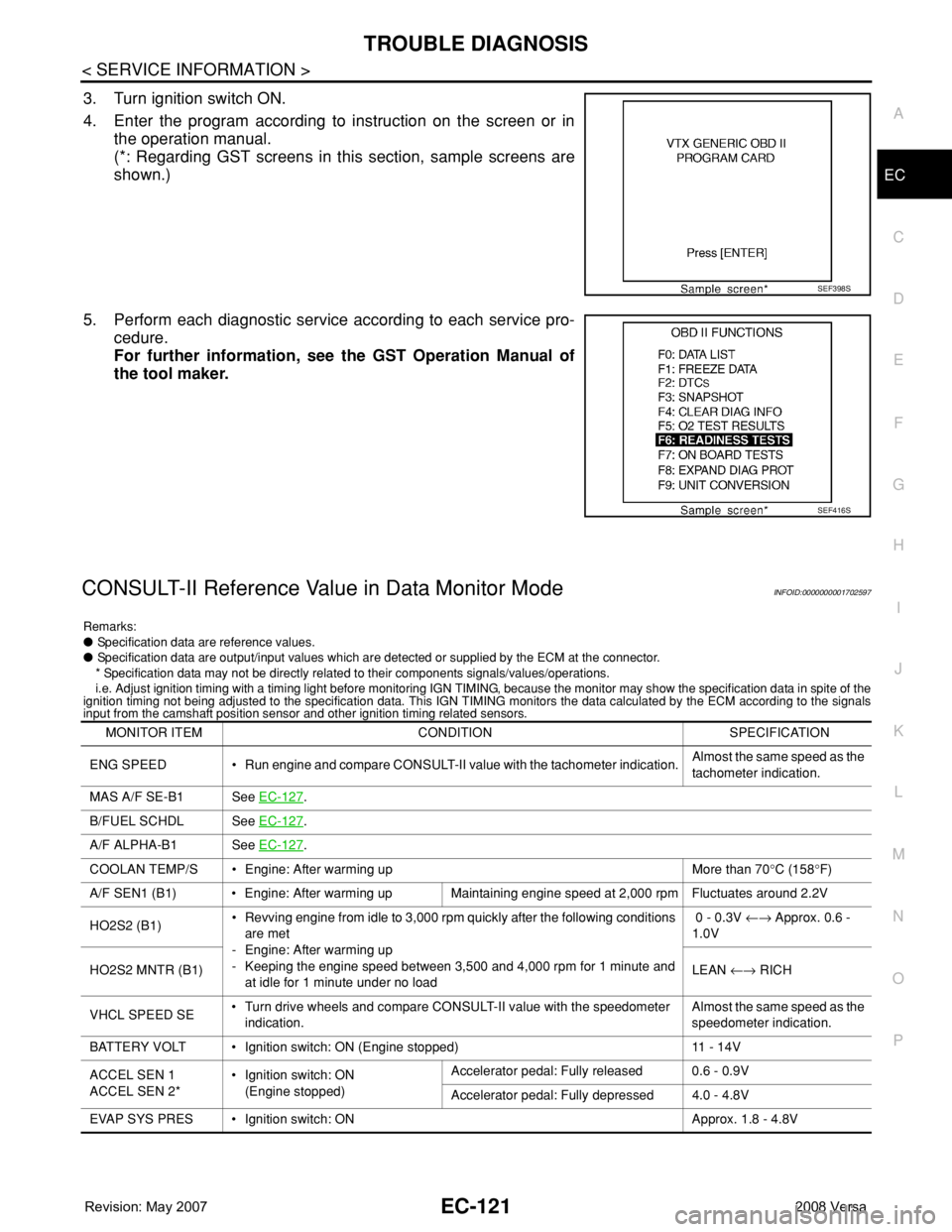
3. Turn ignition switch ON.
4. Enter the program according to instruction on the screen or in
the operation manual.
(*: Regarding GST screens in this section, sample screens are
shown.)
5. Perform each diagnostic service according to each service pro-
cedure.
For further information, see the GST Operation Manual of
the tool maker.
CONSULT-II Reference Value in Data Monitor ModeINFOID:0000000001702597
Remarks:
● Specification data are reference values.
● Specification data are output/input values which are detected or supplied by the ECM at the connector.
* Specification data may not be directly related to their components signals/values/operations.
i.e. Adjust ignition timing with a timing light before monitoring IGN TIMING, because the monitor may show the specification data in spite of the
ignition timing not being adjusted to the specification data. This IGN TIMING monitors the data calculated by the ECM according to the signals
input from the camshaft position sensor and other ignition timing related sensors.
SEF398S
SEF416S
MONITOR ITEM CONDITION SPECIFICATION
ENG SPEED • Run engine and compare CONSULT-II value with the tachometer indication.Almost the same speed as the
tachometer indication.
MAS A/F SE-B1 See EC-127
.
B/FUEL SCHDL See EC-127
.
A/F ALPHA-B1 See EC-127
.
COOLAN TEMP/S • Engine: After warming up More than 70°C (158°F)
A/F SEN1 (B1) • Engine: After warming up Maintaining engine speed at 2,000 rpm Fluctuates around 2.2V
HO2S2 (B1)• Revving engine from idle to 3,000 rpm quickly after the following conditions
are met
- Engine: After warming up
- Keeping the engine speed between 3,500 and 4,000 rpm for 1 minute and
at idle for 1 minute under no load 0 - 0.3V ←→ Approx. 0.6 -
1.0V
HO2S2 MNTR (B1)LEAN ←→ RICH
VHCL SPEED SE• Turn drive wheels and compare CONSULT-II value with the speedometer
indication.Almost the same speed as the
speedometer indication.
BATTERY VOLT • Ignition switch: ON (Engine stopped) 11 - 14V
ACCEL SEN 1
ACCEL SEN 2*• Ignition switch: ON
(Engine stopped)Accelerator pedal: Fully released 0.6 - 0.9V
Accelerator pedal: Fully depressed 4.0 - 4.8V
EVAP SYS PRES • Ignition switch: ON Approx. 1.8 - 4.8V