2008 NISSAN TIIDA Fan belt
[x] Cancel search: Fan beltPage 423 of 2771

BCM (BODY CONTROL MODULE)
BCS-7
< SERVICE INFORMATION >
C
D
E
F
G
H
I
J
L
MA
B
BCS
N
O
P
CAN Communication System DescriptionINFOID:0000000001704585
Refer to LAN-6, "System Description".
Panic alarm• Key switch
•KeyfobIPDM E/R
Vehicle security system• All door switches
•Keyfob
• Door lock/unlock switch
• Trunk key cylinder switch (Se-
dan)
• Front door key cylinder switch
LH• IPDM/ER
• Security indicator lamp
Battery saver control• Ignition switch
• Combination switchIPDM E/R
Headlamp Combination switch IPDM E/R
Tail lamp Combination switch IPDM E/R
Front fog lamp Combination switch IPDM E/R
Turn signal lamp Combination switch• Turn signal lamp
• Combination meter
Hazard lamp Hazard switch• Turn signal lamp
• Combination meter
Room lamp timer• Key switch
•Keyfob
• Main power window and door
lock/unlock switch
• Front door switch LH
• All door switchInterior room lamp
Back door switch signal (Hatchback) Back door lock assembly Luggage room lamp
Back door lock signal (Hatchback) Back door lock assembly Back door opener
Trunk lamp switch signalTrunk lamp switch and trunk re-
lease solenoidLuggage room lamp
Trunk lid opener signalTrunk lamp switch and trunk re-
lease solenoidTrunk lid opener
Key warning chime• Key switch
• Front door switch LHCombination meter (warning buzzer)
Light warning chime• Combination switch
• Key switch
• Front door switch LHCombination meter (warning buzzer)
Seat belt warning chime• Seat belt buckle switch LH
• Ignition switchCombination meter (warning buzzer)
Front wiper and washer system• Combination switch
• Ignition switchIPDM E/R
Rear window defogger Rear window defogger switch IPDM E/R
Rear wiper and washer system• Combination switch
• Ignition switchRear wiper motor
A/C switch signal Front air control ECM
Blower fan switch signal Front air control ECM
A/C indicator signal Front air control A/C indicator
Low tire pressure warning system Remote keyless entry receiver Combination meterSystem Input Output
Page 818 of 2771
CO-1
ENGINE
C
D
E
F
G
H
I
J
K
L
M
SECTION CO
A
CO
N
O
P
CONTENTS
ENGINE COOLING SYSTEM
SERVICE INFORMATION ............................2
PRECAUTIONS ...................................................2
Precaution for Supplemental Restraint System
(SRS) "AIR BAG" and "SEAT BELT PRE-TEN-
SIONER" ...................................................................
2
Precaution Necessary for Steering Wheel Rota-
tion After Battery Disconnect .....................................
2
Precaution for Liquid Gasket .....................................2
PREPARATION ...................................................4
Special Service Tool .................................................4
Commercial Service Tool ..........................................4
OVERHEATING CAUSE ANALYSIS ..................5
Troubleshooting Chart ...............................................5
COOLING SYSTEM ............................................7
Cooling Circuit ...........................................................7
ENGINE COOLANT ............................................8
Inspection ..................................................................8
Changing Engine Coolant .........................................8
RADIATOR .........................................................11
Component ..............................................................11
Removal and Installation .........................................11
Checking Radiator Cap ...........................................13
Checking Radiator ...................................................13
COOLING FAN ..................................................14
Component (Models with A/C) .................................14
Component (Models without A/C) ............................14
Removal and Installation .........................................15
DISASSEMBLY AND ASSEMBLY ..........................15
WATER PUMP ..................................................16
Component ..............................................................16
Removal and Installation .........................................16
THERMOSTAT ..................................................17
Component ..............................................................17
Removal and Installation .........................................17
WATER OUTLET AND WATER CONTROL
VALVE ...............................................................
19
Component ..............................................................19
Removal and Installation .........................................19
SERVICE DATA AND SPECIFICATIONS
(SDS) .................................................................
22
Standard and Limit ..................................................22
Page 822 of 2771
OVERHEATING CAUSE ANALYSIS
CO-5
< SERVICE INFORMATION >
C
D
E
F
G
H
I
J
K
L
MA
CO
N
P O
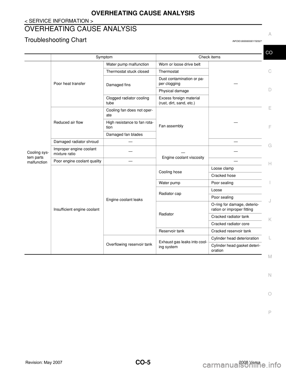
OVERHEATING CAUSE ANALYSIS
Troubleshooting ChartINFOID:0000000001702527
Symptom Check items
Cooling sys-
tem parts
malfunctionPoor heat transferWater pump malfunction Worn or loose drive belt
— Thermostat stuck closed Thermostat
Damaged finsDust contamination or pa-
per clogging
Physical damage
Clogged radiator cooling
tubeExcess foreign material
(rust, dirt, sand, etc.)
Reduced air flowCooling fan does not oper-
ate
Fan assembly— High resistance to fan rota-
tion
Damaged fan blades
Damaged radiator shroud — —
Improper engine coolant
mixture ratio—
—
Engine coolant viscosity—
Poor engine coolant quality — —
Insufficient engine coolantEngine coolant leaksCooling hoseLoose clamp
Cracked hose
Water pump Poor sealing
Radiator capLoose
Poor sealing
RadiatorO-ring for damage, deterio-
ration or improper fitting
Cracked radiator tank
Cracked radiator core
Reservoir tank Cracked reservoir tank
Overflowing reservoir tankExhaust gas leaks into cool-
ing systemCylinder head deterioration
Cylinder head gasket deteri-
oration
Page 829 of 2771
CO-12
< SERVICE INFORMATION >
RADIATOR
Do not remove radiator cap when the engine is hot. Serious burns could occur from high-pressure
engine coolant escaping from radiator. Wrap a thick cloth around the cap. Slowly turn it a quarter of a
turn to release built-up pressure. Carefully remove radiator cap by turning it all the way.
REMOVAL
1. Drain engine coolant from radiator. Refer to CO-8, "Changing Engine Coolant".
CAUTION:
• Perform this step when engine is cold.
• Do not spill engine coolant on drive belt.
2. Remove air duct (inlet). Refer to EM-16
.
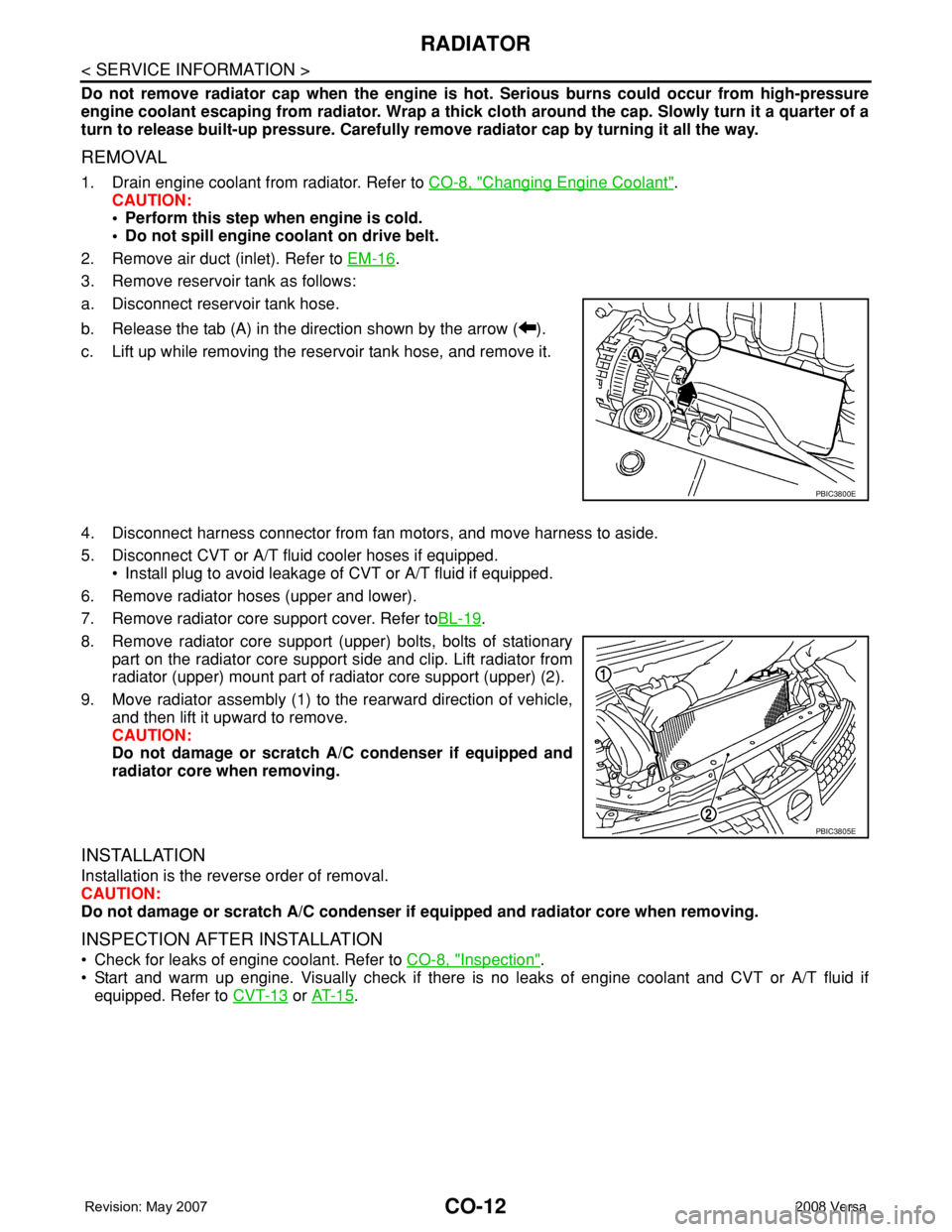
3. Remove reservoir tank as follows:
a. Disconnect reservoir tank hose.
b. Release the tab (A) in the direction shown by the arrow ( ).
c. Lift up while removing the reservoir tank hose, and remove it.
4. Disconnect harness connector from fan motors, and move harness to aside.
5. Disconnect CVT or A/T fluid cooler hoses if equipped.
• Install plug to avoid leakage of CVT or A/T fluid if equipped.
6. Remove radiator hoses (upper and lower).
7. Remove radiator core support cover. Refer toBL-19
.
8. Remove radiator core support (upper) bolts, bolts of stationary
part on the radiator core support side and clip. Lift radiator from
radiator (upper) mount part of radiator core support (upper) (2).
9. Move radiator assembly (1) to the rearward direction of vehicle,
and then lift it upward to remove.
CAUTION:
Do not damage or scratch A/C condenser if equipped and
radiator core when removing.
INSTALLATION
Installation is the reverse order of removal.
CAUTION:
Do not damage or scratch A/C condenser if equipped and radiator core when removing.
INSPECTION AFTER INSTALLATION
• Check for leaks of engine coolant. Refer to CO-8, "Inspection".
• Start and warm up engine. Visually check if there is no leaks of engine coolant and CVT or A/T fluid if
equipped. Refer to CVT-13
or AT- 1 5.
PBIC3800E
PBIC3805E
Page 832 of 2771
COOLING FAN
CO-15
< SERVICE INFORMATION >
C
D
E
F
G
H
I
J
K
L
MA
CO
N
P O
Removal and InstallationINFOID:0000000001702537
REMOVAL
1. Drain engine coolant from radiator. Refer to CO-8, "Changing Engine Coolant".
CAUTION:
• Perform this step when engine is cold.
• Do not spill engine coolant on drive belt.
2. Remove air duct (inlet). Refer to EM-16, "
Component".
3. Remove reservoir tank. Refer to CO-11, "
Component".
4. Disconnect radiator hose (upper) at radiator side. Refer to CO-11, "
Component".
5. Disconnect harness connectors from fan motor, and move harness to aside.
6. Remove cooling fan assembly.
CAUTION:
Be careful not to damage or scratch the radiator core.
INSTALLATION
Installation is the reverse order of removal.
• Cooling fans are controlled by ECM. For details, refer to EC-412
.
CAUTION:
Be careful not to damage or scratch the radiator core.
DISASSEMBLY AND ASSEMBLYINFOID:0000000001702538
Disassembly
1. Remove cooling fan from fan motor.
2. Remove fan motor from fan shroud.
Inspection After Disassembly
Inspect cooling fan for crack or unusual bend.
• If anything is found, replace cooling fan.
Assembly
Assembly is the reverse order of disassembly.
Page 1750 of 2771
ENGINE ASSEMBLY
EM-73
< SERVICE INFORMATION >
C
D
E
F
G
H
I
J
K
L
MA
EM
N
P O
• Use either 2-pole lift type or separate type lift as best you can. If board-on type is used for unavoid-
able reasons, support at the rear axle jacking point with a transmission jack or similar tool before
starting work, in preparation for the backward shift of center of gravity.
• For supporting points for lifting and jacking point at rear axle, refer to GI-38, "
Garage Jack and
Safety Stand and 2-Pole Lift".
REMOVAL
Remove the engine and the transaxle assembly from the vehicle downward. Separate the engine and the tran-
saxle.
1. Remove engine undercover
2. Drain engine coolant from radiator. Refer to CO-8, "
Changing Engine Coolant".
CAUTION:
• Perform this step when the engine is cold.
• Do not spill engine coolant on drive belt.
3. Remove front fender protector (RH and LH); Refer to EI-23
.
4. Remove exhaust front tube; Refer to EX-4
.
5. Remove drive shafts (LH and RH) from steering knuckle. Refer to FAX-8
.
6. Remove transaxle joint bolts which pierce at oil pan (upper) lower rear side. Refer to AT-226
(A/T models),
CVT-178
(CVT) or MT-16 (M/T models).
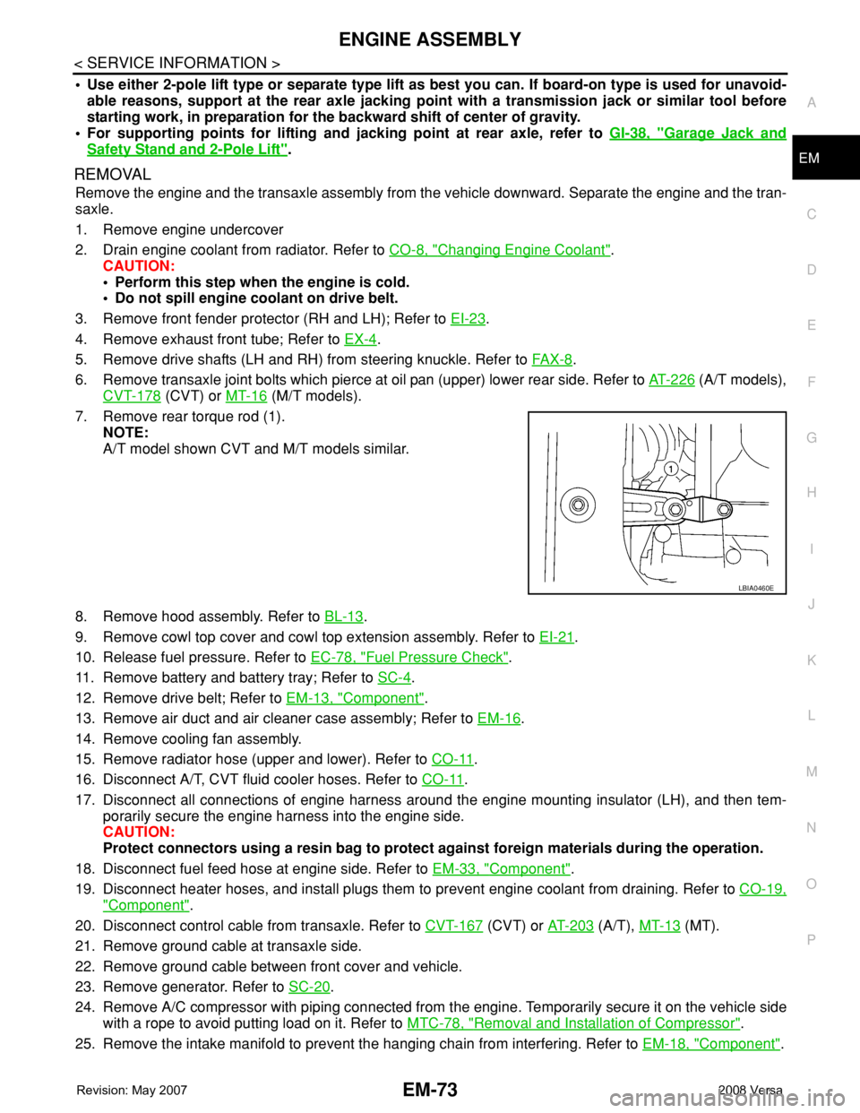
7. Remove rear torque rod (1).
NOTE:
A/T model shown CVT and M/T models similar.
8. Remove hood assembly. Refer to BL-13
.
9. Remove cowl top cover and cowl top extension assembly. Refer to EI-21
.
10. Release fuel pressure. Refer to EC-78, "
Fuel Pressure Check".
11. Remove battery and battery tray; Refer to SC-4
.
12. Remove drive belt; Refer to EM-13, "
Component".
13. Remove air duct and air cleaner case assembly; Refer to EM-16
.
14. Remove cooling fan assembly.
15. Remove radiator hose (upper and lower). Refer to CO-11
.
16. Disconnect A/T, CVT fluid cooler hoses. Refer to CO-11
.
17. Disconnect all connections of engine harness around the engine mounting insulator (LH), and then tem-
porarily secure the engine harness into the engine side.
CAUTION:
Protect connectors using a resin bag to protect against foreign materials during the operation.
18. Disconnect fuel feed hose at engine side. Refer to EM-33, "
Component".
19. Disconnect heater hoses, and install plugs them to prevent engine coolant from draining. Refer to CO-19,
"Component".
20. Disconnect control cable from transaxle. Refer to CVT-167
(CVT) or AT-203 (A/T), MT-13 (MT).
21. Remove ground cable at transaxle side.
22. Remove ground cable between front cover and vehicle.
23. Remove generator. Refer to SC-20
.
24. Remove A/C compressor with piping connected from the engine. Temporarily secure it on the vehicle side
with a rope to avoid putting load on it. Refer to MTC-78, "
Removal and Installation of Compressor".
25. Remove the intake manifold to prevent the hanging chain from interfering. Refer to EM-18, "
Component".
LBIA0460E
Page 2339 of 2771
MTC-1
AIR CONDITIONER
C
D
E
F
G
H
I
K
L
M
SECTION MTC
A
B
MTC
N
O
P
CONTENTS
MANUAL AIR CONDITIONER
SERVICE INFORMATION ............................3
PRECAUTIONS ...................................................3
Precaution for Supplemental Restraint System
(SRS) "AIR BAG" and "SEAT BELT PRE-TEN-
SIONER" ...................................................................
3
Precaution for Procedure without Cowl Top Cover ......3
Precaution for Working with HFC-134a (R-134a) ......3
General Refrigerant Precaution ................................4
Oil Precaution ............................................................4
Precaution for Refrigerant Connection ......................4
Precaution for Service of Compressor ......................7
Precaution for Service Equipment .............................7
Precaution for Leak Detection Dye ...........................9
PREPARATION ..................................................10
Special Service Tool ...............................................10
HFC-134a (R-134a) Service Tool and Equipment ....10
Commercial Service Tool ........................................13
REFRIGERATION SYSTEM ..............................14
Refrigerant Cycle ....................................................14
Refrigerant System Protection ................................14
Component Part Location .......................................15
OIL ......................................................................16
Maintenance of Oil Quantity in Compressor ...........16
AIR CONDITIONER CONTROL .........................19
Control Operation ....................................................19
Discharge Air Flow ..................................................20
System Description .................................................20
CAN Communication System Description ...............21
TROUBLE DIAGNOSIS .....................................22
CONSULT-III Function (BCM) .................................22
How to Perform Trouble Diagnosis for Quick and
Accurate Repair ......................................................
22
Component Parts and Harness Connector Loca-
tion ..........................................................................
23
Schematic ...............................................................25
Wiring Diagram - Heater - .......................................26
Wiring Diagram - A/C,M - ........................................27
Operational Check ...................................................30
Mode Door ...............................................................31
Air Mix Door .............................................................32
Intake Door ..............................................................33
Front Blower Motor Circuit .......................................33
Magnet Clutch Circuit (If Equipped) .........................37
Insufficient Cooling ..................................................45
Insufficient Heating ..................................................52
Noise .......................................................................53
CONTROLLER ..................................................55
Removal and Installation .........................................55
Disassembly and Assembly .....................................56
THERMO CONTROL AMPLIFIER ....................57
Removal and Installation .........................................57
A/C UNIT ASSEMBLY ......................................58
Removal and Installation .........................................58
Disassembly and Assembly .....................................60
BLOWER MOTOR ............................................62
Removal and Installation .........................................62
INTAKE DOOR ..................................................63
Intake Door Cable Adjustment .................................63
AIR MIX DOOR .................................................64
Air Mix Door Cable Adjustment ...............................64
MODE DOOR ....................................................65
Mode Door Cable Adjustment .................................65
BLOWER FAN RESISTOR ...............................66
Removal and Installation .........................................66
HEATER CORE .................................................67
Removal and Installation .........................................67
AIR CONDITIONER FILTER .............................68
Removal and Installation .........................................68
Page 2375 of 2771
TROUBLE DIAGNOSIS
MTC-37
< SERVICE INFORMATION >
C
D
E
F
G
H
I
K
L
MA
B
MTC
N
O
P
OK >> GO TO 11.
NG >> Repair harness or connector.
11 .CHECK FAN SWITCH
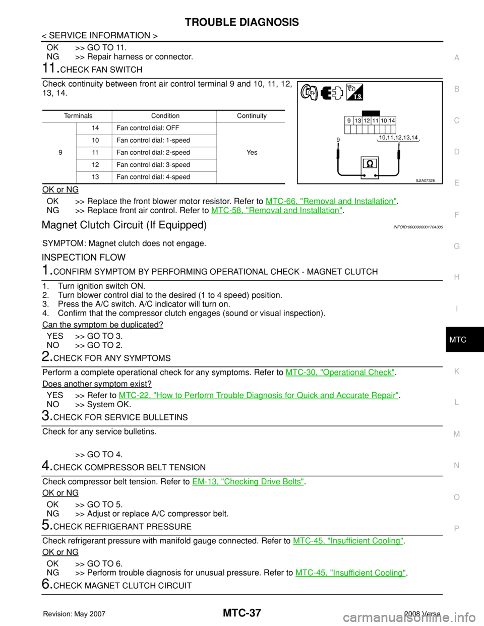
Check continuity between front air control terminal 9 and 10, 11, 12,
13, 14.
OK or NG
OK >> Replace the front blower motor resistor. Refer to MTC-66, "Removal and Installation".
NG >> Replace front air control. Refer to MTC-58, "
Removal and Installation".
Magnet Clutch Circuit (If Equipped)INFOID:0000000001704305
SYMPTOM: Magnet clutch does not engage.
INSPECTION FLOW
1.CONFIRM SYMPTOM BY PERFORMING OPERATIONAL CHECK - MAGNET CLUTCH
1. Turn ignition switch ON.
2. Turn blower control dial to the desired (1 to 4 speed) position.
3. Press the A/C switch. A/C indicator will turn on.
4. Confirm that the compressor clutch engages (sound or visual inspection).
Can the symptom be duplicated?
YES >> GO TO 3.
NO >> GO TO 2.
2.CHECK FOR ANY SYMPTOMS
Perform a complete operational check for any symptoms. Refer to MTC-30, "
Operational Check".
Does another symptom exist?
YES >> Refer to MTC-22, "How to Perform Trouble Diagnosis for Quick and Accurate Repair".
NO >> System OK.
3.CHECK FOR SERVICE BULLETINS
Check for any service bulletins.
>> GO TO 4.
4.CHECK COMPRESSOR BELT TENSION
Check compressor belt tension. Refer to EM-13, "
Checking Drive Belts".
OK or NG
OK >> GO TO 5.
NG >> Adjust or replace A/C compressor belt.
5.CHECK REFRIGERANT PRESSURE
Check refrigerant pressure with manifold gauge connected. Refer to MTC-45, "
Insufficient Cooling".
OK or NG
OK >> GO TO 6.
NG >> Perform trouble diagnosis for unusual pressure. Refer to MTC-45, "
Insufficient Cooling".
6.CHECK MAGNET CLUTCH CIRCUIT
Terminals Condition Continuity
914 Fan control dial: OFF
Ye s 10 Fan control dial: 1-speed
11 Fan control dial: 2-speed
12 Fan control dial: 3-speed
13 Fan control dial: 4-speed
SJIA0732E