2008 NISSAN TIIDA Transaxle Assembly
[x] Cancel search: Transaxle AssemblyPage 16 of 2771

AT-4
Diagnosis Procedure .............................................210
KEY INTERLOCK CABLE ...............................213
Removal and Installation .......................................213
ON-VEHICLE SERVICE ..................................216
Control Valve Assembly and Accumulators ...........216
Park/Neutral Position (PNP) Switch ......................219
Revolution Sensor .................................................221
Turbine Revolution Sensor (Power Train Revolu-
tion Sensor) ...........................................................
222
Differential Side Oil Seal ........................................223
AIR BREATHER HOSE ...................................225
Removal and Installation .......................................225
TRANSAXLE ASSEMBLY ..............................226
Removal and Installation .......................................226
OVERHAUL .....................................................230
Component ............................................................230
Oil Channel ............................................................237
Location of Adjusting Shims, Needle Bearings and
Thrust Washers .....................................................
238
Location of Snap Rings .........................................239
DISASSEMBLY ...............................................240
Disassembly ..........................................................240
REPAIR FOR COMPONENT PARTS ..............257
Manual Shaft .........................................................257
Oil Pump ................................................................260
Control Valve Assembly ........................................263
Control Valve Upper Body .....................................272
Control Valve Lower Body .....................................276
Reverse Clutch ......................................................279
High Clutch ............................................................284
Forward and Overrun Clutches .............................288
Low & Reverse Brake ............................................295
Rear Internal Gear and Forward Clutch Hub .........299
Output Shaft, Output Gear, Idler Gear, Reduction
Pinion Gear and Bearing Retainer .........................
302
Band Servo Piston Assembly ................................307
Final Drive .............................................................313
ASSEMBLY ......................................................318
Assembly (1) .........................................................318
Adjustment (1) .......................................................319
Assembly (2) .........................................................325
Adjustment (2) .......................................................330
Assembly (3) .........................................................333
SERVICE DATA AND SPECIFICATIONS
(SDS) ................................................................
341
General Specification ............................................341
Vehicle Speed at Which Gear Shifting Occurs .....341
Vehicle Speed at When Lock-up Occurs/Releases
.
341
Stall Speed ............................................................341
Line Pressure ........................................................341
Adjusting shims, Needle Bearings, Thrust Wash-
ers and Snap Rings ..............................................
341
Control Valves .......................................................343
Accumulator ..........................................................343
Clutches and Brakes .............................................343
Final Drive .............................................................345
Planetary Carrier ...................................................345
Oil Pump ...............................................................345
Input Shaft .............................................................345
Reduction Pinion Gear ..........................................345
Band Servo ...........................................................345
Output Shaft ..........................................................346
Bearing Retainer ...................................................346
Total End Play .......................................................346
Reverse Clutch End Play ......................................346
Removal and Installation .......................................346
Shift Solenoid Valves ............................................346
Solenoid Valves ....................................................346
A/T Fluid Temperature Sensor ..............................347
Revolution Sensor .................................................347
Dropping Resistor .................................................347
Turbine Revolution Sensor (Power Train Revolu-
tion Sensor) ...........................................................
347
Page 20 of 2771
AT-8
< SERVICE INFORMATION >
PRECAUTIONS
• Be sure to turn the ignition switch OFF and disconnect battery negative cable from battery negative
terminal before any repair or inspection work. The open/short circuit of related switches, sensors,
solenoid valves, etc. will cause the MIL to light up.
• Be sure to connect and lock the connectors securely after work. A loose (unlocked) connector will
cause the MIL to light up due to an open circuit. (Be sure the connectors are free from water, grease,
dirt, bent terminals, etc.)
• Be sure to route and secure the harnesses properly after work. Interference of the harness with a
bracket, etc. may cause the MIL to light up due to a short circuit.
• Be sure to erase the unnecessary malfunction information (repairs completed) from the TCM and
ECM before returning the vehicle to the customer.
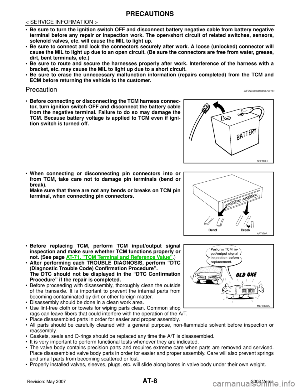
PrecautionINFOID:0000000001703154
•Before connecting or disconnecting the TCM harness connec-
tor, turn ignition switch OFF and disconnect the battery cable
from the negative terminal. Failure to do so may damage the
TCM. Because battery voltage is applied to TCM even if igni-
tion switch is turned off.
•When connecting or disconnecting pin connectors into or
from TCM, take care not to damage pin terminals (bend or
break).
Make sure that there are not any bends or breaks on TCM pin
terminal, when connecting pin connectors.
•Before replacing TCM, perform TCM input/output signal
inspection and make sure whether TCM functions properly or
not. (See page AT-71, "
TCM Terminal and Reference Value".)
•After performing each TROUBLE DIAGNOSIS, perform “DTC
(Diagnostic Trouble Code) Confirmation Procedure”.
The DTC should not be displayed in the “DTC Confirmation
Procedure” if the repair is completed.
• Before proceeding with disassembly, thoroughly clean the outside
of the transaxle. It is important to prevent the internal parts from
becoming contaminated by dirt or other foreign matter.
• Disassembly should be done in a clean work area.
• Use lint-free cloth or towels for wiping parts clean. Common shop
rags can leave fibers that could interfere with the operation of the A/T.
• Place disassembled parts in order for easier and proper assembly.
• All parts should be carefully cleaned with a general purpose, non-flammable solvent before inspection or
reassembly.
• Gaskets, seals and O-rings should be replaced any time the A/T is disassembled.
• It is very important to perform functional tests whenever they are indicated.
• The valve body contains precision parts and requires extreme care when parts are removed and serviced.
Place disassembled valve body parts in order for easier and proper assembly. Care will also prevent springs
and small parts from becoming scattered or lost.
• Properly installed valves, sleeves, plugs, etc. will slide along bores in valve body under their own weight.
SEF289H
AAT470A
MEF040DA
Page 80 of 2771
AT-68
< SERVICE INFORMATION >
TROUBLE DIAGNOSIS
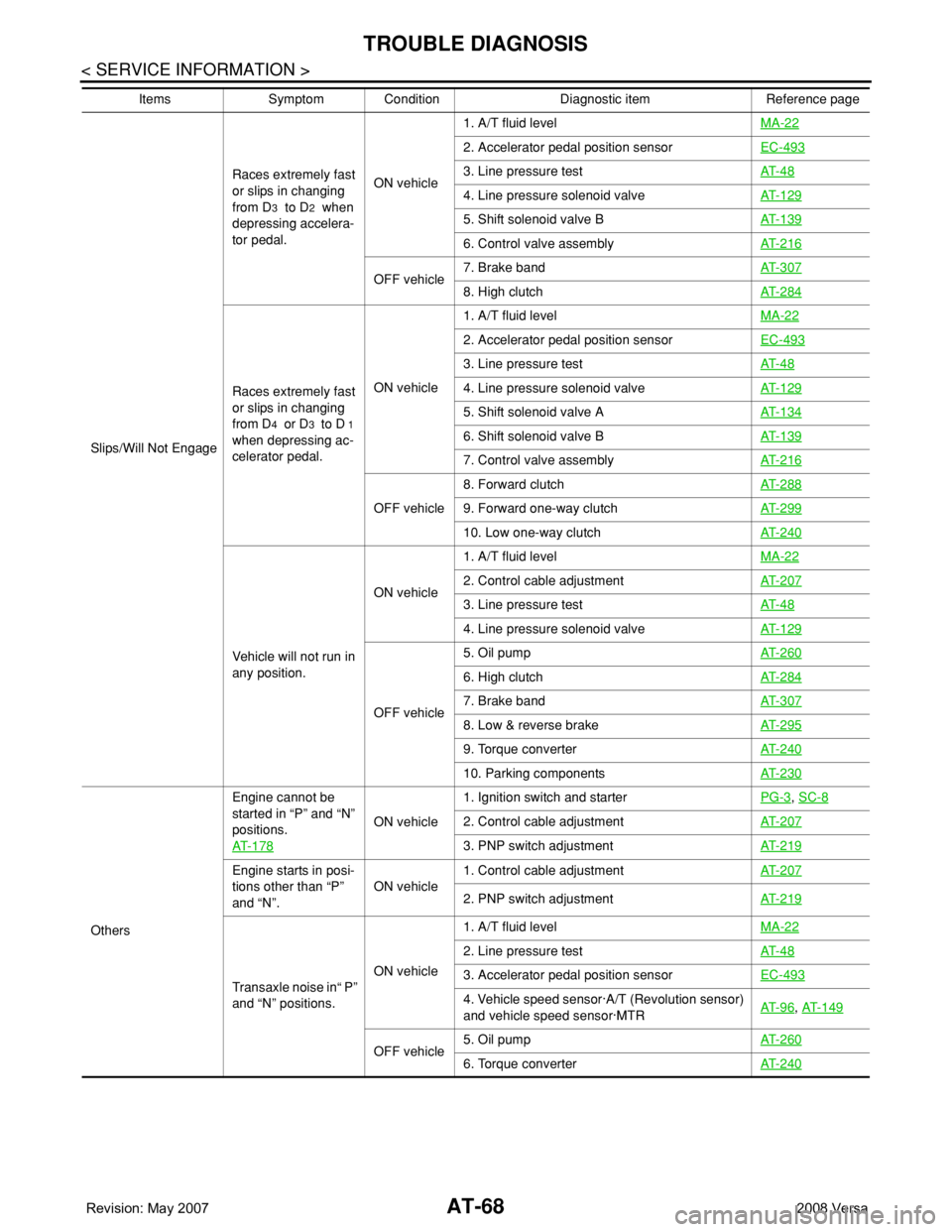
Slips/Will Not EngageRaces extremely fast
or slips in changing
from D
3 to D2 when
depressing accelera-
tor pedal. ON vehicle1. A/T fluid levelMA-22
2. Accelerator pedal position sensor EC-493
3. Line pressure testAT- 4 8
4. Line pressure solenoid valveAT- 1 2 9
5. Shift solenoid valve BAT- 1 3 9
6. Control valve assemblyAT- 2 1 6
OFF vehicle7. Brake bandAT- 3 0 78. High clutchAT- 2 8 4
Races extremely fast
or slips in changing
from D
4 or D3 to D 1
when depressing ac-
celerator pedal.ON vehicle1. A/T fluid levelMA-22
2. Accelerator pedal position sensorEC-493
3. Line pressure testAT- 4 8
4. Line pressure solenoid valveAT- 1 2 9
5. Shift solenoid valve AAT- 1 3 4
6. Shift solenoid valve BAT- 1 3 9
7. Control valve assemblyAT- 2 1 6
OFF vehicle8. Forward clutchAT- 2 8 89. Forward one-way clutchAT- 2 9 9
10. Low one-way clutchAT- 2 4 0
Vehicle will not run in
any position.ON vehicle1. A/T fluid levelMA-22
2. Control cable adjustmentAT- 2 0 7
3. Line pressure testAT- 4 8
4. Line pressure solenoid valveAT- 1 2 9
OFF vehicle5. Oil pumpAT- 2 6 0
6. High clutchAT- 2 8 4
7. Brake bandAT- 3 0 7
8. Low & reverse brakeAT- 2 9 5
9. Torque converterAT- 2 4 0
10. Parking componentsAT- 2 3 0
OthersEngine cannot be
started in “P” and “N”
positions.
AT- 1 7 8
ON vehicle1. Ignition switch and starterPG-3
, SC-8
2. Control cable adjustmentAT- 2 0 7
3. PNP switch adjustmentAT- 2 1 9
Engine starts in posi-
tions other than “P”
and “N”.ON vehicle1. Control cable adjustmentAT- 2 0 7
2. PNP switch adjustmentAT- 2 1 9
Transaxle noise in“ P”
and “N” positions.ON vehicle1. A/T fluid levelMA-22
2. Line pressure testAT- 4 8
3. Accelerator pedal position sensorEC-493
4. Vehicle speed sensor·A/T (Revolution sensor)
and vehicle speed sensor·MTRAT- 9 6, AT- 1 4 9
OFF vehicle5. Oil pumpAT- 2 6 06. Torque converterAT- 2 4 0
Items Symptom Condition Diagnostic item Reference page
Page 82 of 2771
AT-70
< SERVICE INFORMATION >
TROUBLE DIAGNOSIS
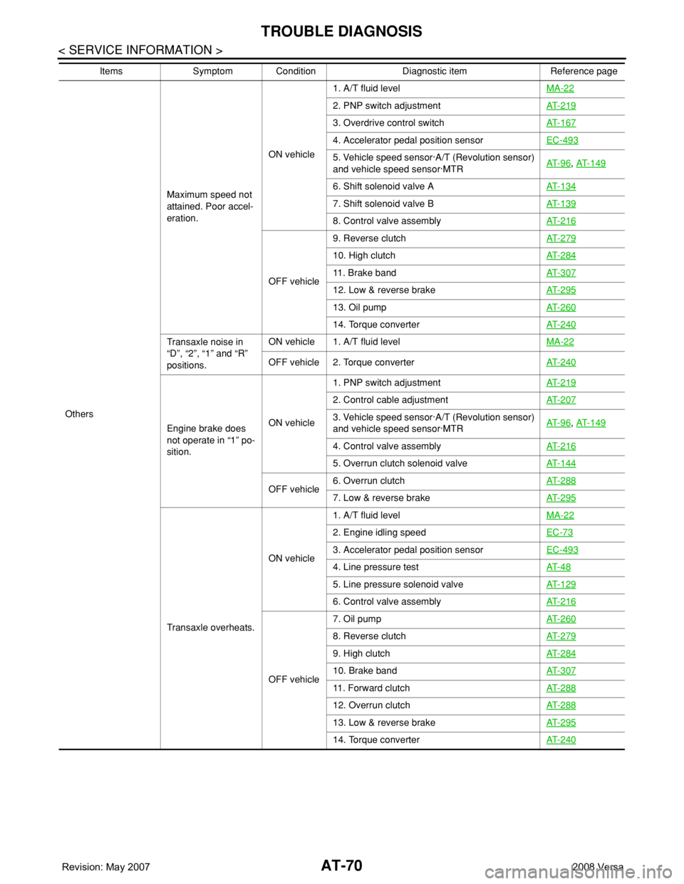
OthersMaximum speed not
attained. Poor accel-
eration.ON vehicle1. A/T fluid levelMA-22
2. PNP switch adjustmentAT- 2 1 9
3. Overdrive control switchAT- 1 6 7
4. Accelerator pedal position sensorEC-493
5. Vehicle speed sensor·A/T (Revolution sensor)
and vehicle speed sensor·MTRAT- 9 6, AT- 1 4 9
6. Shift solenoid valve AAT- 1 3 4
7. Shift solenoid valve BAT- 1 3 9
8. Control valve assemblyAT- 2 1 6
OFF vehicle9. Reverse clutchAT- 2 7 9
10. High clutchAT- 2 8 4
11. Brake bandAT- 3 0 7
12. Low & reverse brakeAT- 2 9 5
13. Oil pumpAT- 2 6 0
14. Torque converterAT- 2 4 0
Transaxle noise in
“D”, “2”, “1” and “R”
positions.ON vehicle 1. A/T fluid levelMA-22
OFF vehicle 2. Torque converterAT- 2 4 0
Engine brake does
not operate in “1” po-
sition.ON vehicle1. PNP switch adjustmentAT- 2 1 9
2. Control cable adjustmentAT- 2 0 7
3. Vehicle speed sensor·A/T (Revolution sensor)
and vehicle speed sensor·MTRAT- 9 6, AT- 1 4 9
4. Control valve assemblyAT- 2 1 6
5. Overrun clutch solenoid valveAT- 1 4 4
OFF vehicle6. Overrun clutchAT- 2 8 87. Low & reverse brakeAT- 2 9 5
Transaxle overheats.ON vehicle1. A/T fluid levelMA-22
2. Engine idling speedEC-73
3. Accelerator pedal position sensorEC-493
4. Line pressure testAT- 4 8
5. Line pressure solenoid valveAT- 1 2 9
6. Control valve assemblyAT- 2 1 6
OFF vehicle7. Oil pumpAT- 2 6 0
8. Reverse clutchAT- 2 7 9
9. High clutchAT- 2 8 4
10. Brake bandAT- 3 0 7
11. Forward clutchAT- 2 8 8
12. Overrun clutchAT- 2 8 8
13. Low & reverse brakeAT- 2 9 5
14. Torque converterAT- 2 4 0
Items Symptom Condition Diagnostic item Reference page
Page 98 of 2771
AT-86
< SERVICE INFORMATION >
DTC P0705 PARK/NEUTRAL POSITION (PNP) SWITCH
DTC P0705 PARK/NEUTRAL POSITION (PNP) SWITCH
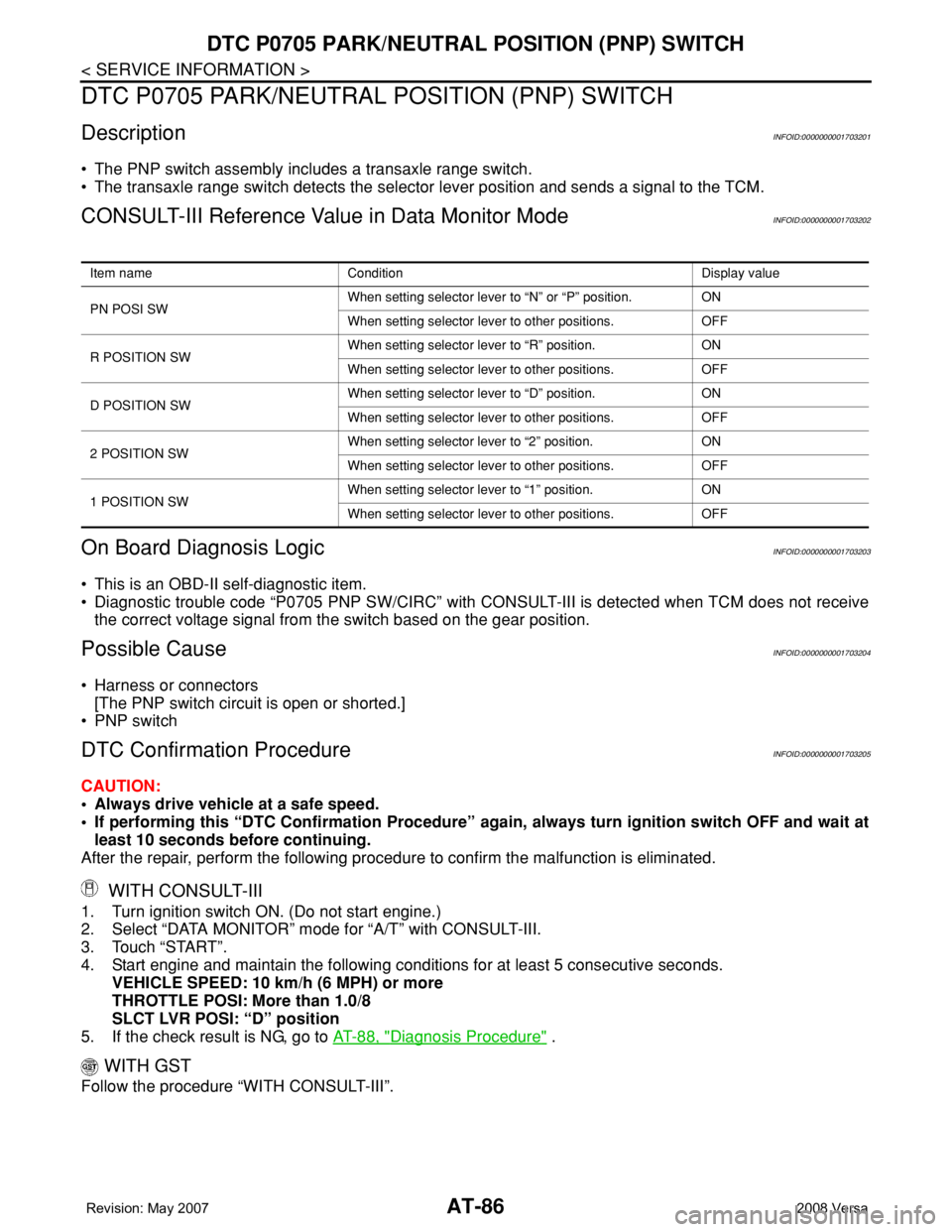
DescriptionINFOID:0000000001703201
• The PNP switch assembly includes a transaxle range switch.
• The transaxle range switch detects the selector lever position and sends a signal to the TCM.
CONSULT-III Reference Value in Data Monitor ModeINFOID:0000000001703202
On Board Diagnosis LogicINFOID:0000000001703203
• This is an OBD-II self-diagnostic item.
• Diagnostic trouble code “P0705 PNP SW/CIRC” with CONSULT-III is detected when TCM does not receive
the correct voltage signal from the switch based on the gear position.
Possible CauseINFOID:0000000001703204
• Harness or connectors
[The PNP switch circuit is open or shorted.]
• PNP switch
DTC Confirmation ProcedureINFOID:0000000001703205
CAUTION:
• Always drive vehicle at a safe speed.
• If performing this “DTC Confirmation Procedure” again, always turn ignition switch OFF and wait at
least 10 seconds before continuing.
After the repair, perform the following procedure to confirm the malfunction is eliminated.
WITH CONSULT-III
1. Turn ignition switch ON. (Do not start engine.)
2. Select “DATA MONITOR” mode for “A/T” with CONSULT-III.
3. Touch “START”.
4. Start engine and maintain the following conditions for at least 5 consecutive seconds.
VEHICLE SPEED: 10 km/h (6 MPH) or more
THROTTLE POSI: More than 1.0/8
SLCT LVR POSI: “D” position
5. If the check result is NG, go to AT-88, "
Diagnosis Procedure" .
WITH GST
Follow the procedure “WITH CONSULT-III”.
Item name Condition Display value
PN POSI SWWhen setting selector lever to “N” or “P” position. ON
When setting selector lever to other positions. OFF
R POSITION SWWhen setting selector lever to “R” position. ON
When setting selector lever to other positions. OFF
D POSITION SWWhen setting selector lever to “D” position. ON
When setting selector lever to other positions. OFF
2 POSITION SWWhen setting selector lever to “2” position. ON
When setting selector lever to other positions. OFF
1 POSITION SWWhen setting selector lever to “1” position. ON
When setting selector lever to other positions. OFF
Page 106 of 2771
AT-94
< SERVICE INFORMATION >
DTC P0710 A/T FLUID TEMPERATURE SENSOR CIRCUIT
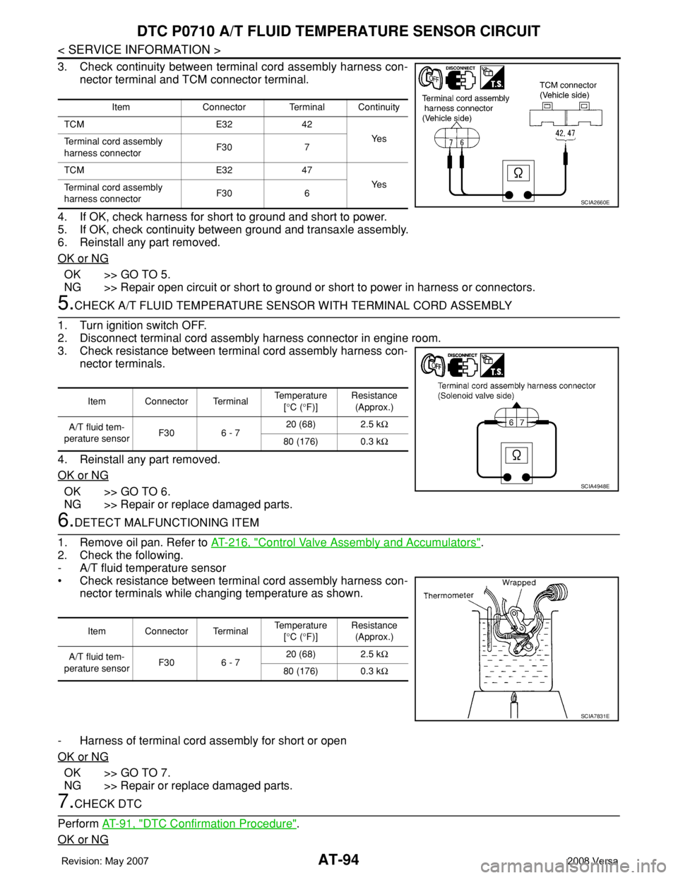
3. Check continuity between terminal cord assembly harness con-
nector terminal and TCM connector terminal.
4. If OK, check harness for short to ground and short to power.
5. If OK, check continuity between ground and transaxle assembly.
6. Reinstall any part removed.
OK or NG
OK >> GO TO 5.
NG >> Repair open circuit or short to ground or short to power in harness or connectors.
5.CHECK A/T FLUID TEMPERATURE SENSOR WITH TERMINAL CORD ASSEMBLY
1. Turn ignition switch OFF.
2. Disconnect terminal cord assembly harness connector in engine room.
3. Check resistance between terminal cord assembly harness con-
nector terminals.
4. Reinstall any part removed.
OK or NG
OK >> GO TO 6.
NG >> Repair or replace damaged parts.
6.DETECT MALFUNCTIONING ITEM
1. Remove oil pan. Refer to AT-216, "
Control Valve Assembly and Accumulators".
2. Check the following.
- A/T fluid temperature sensor
• Check resistance between terminal cord assembly harness con-
nector terminals while changing temperature as shown.
- Harness of terminal cord assembly for short or open
OK or NG
OK >> GO TO 7.
NG >> Repair or replace damaged parts.
7.CHECK DTC
Perform AT-91, "
DTC Confirmation Procedure".
OK or NG
Item Connector Terminal Continuity
TCM E32 42
Ye s
Terminal cord assembly
harness connectorF30 7
TCM E32 47
Ye s
Terminal cord assembly
harness connectorF30 6
SCIA2660E
Item Connector Terminal Temperature
[°C (°F)]Resistance
(Approx.)
A/T fluid tem-
perature sensorF30 6 - 720 (68) 2.5 kΩ
80 (176) 0.3 kΩ
SCIA4948E
Item Connector Terminal Temperature
[°C (°F)]Resistance
(Approx.)
A/T fluid tem-
perature sensorF30 6 - 720 (68) 2.5 kΩ
80 (176) 0.3 kΩ
SCIA7831E
Page 115 of 2771
DTC P0725 ENGINE SPEED SIGNAL
AT-103
< SERVICE INFORMATION >
D
E
F
G
H
I
J
K
L
MA
B
AT
N
O
P
Diagnosis ProcedureINFOID:0000000001703230
1.CHECK DTC WITH ECM
Check DTC with CONSULT-III “ENGINE”.
Turn ignition switch ON and select “SELF-DIAGNOSTIC RESULTS” mode for “ENGINE” with CONSULT-III.
Refer to EC-109, "
CONSULT-II Function (ENGINE)" .
OK or NG
OK >> GO TO 2.
NG >> Check ignition signal circuit for engine control. Refer to EC-531
.
2.CHECK INPUT SIGNAL
With CONSULT-III
1. Start engine.
2. Select “TCM INPUT SIGNALS” in “DATA MONITOR” mode for “A/T” with CONSULT-III.
3. Read out the value of “ENGINE SPEED”. Check engine speed changes according to throttle position.
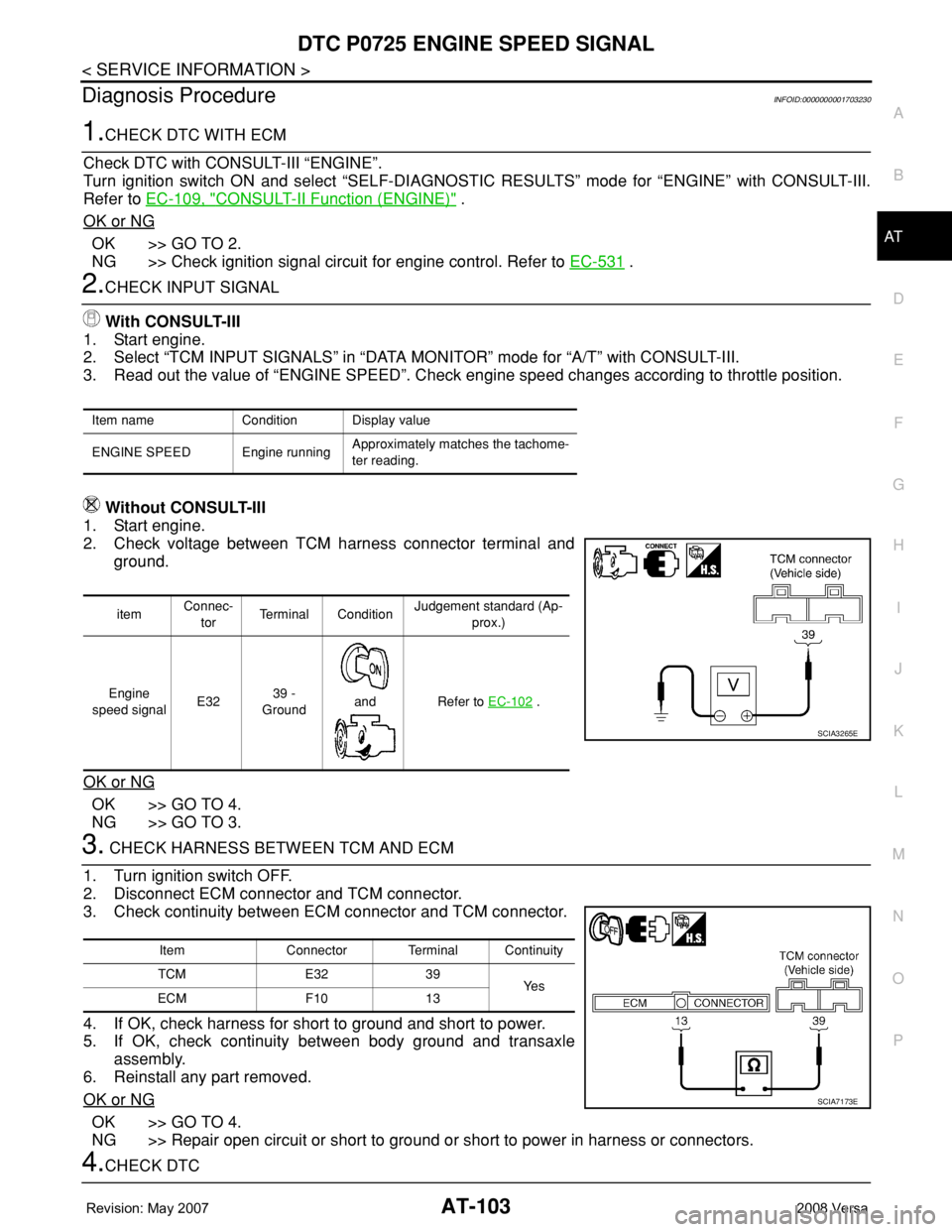
Without CONSULT-III
1. Start engine.
2. Check voltage between TCM harness connector terminal and
ground.
OK or NG
OK >> GO TO 4.
NG >> GO TO 3.
3. CHECK HARNESS BETWEEN TCM AND ECM
1. Turn ignition switch OFF.
2. Disconnect ECM connector and TCM connector.
3. Check continuity between ECM connector and TCM connector.
4. If OK, check harness for short to ground and short to power.
5. If OK, check continuity between body ground and transaxle
assembly.
6. Reinstall any part removed.
OK or NG
OK >> GO TO 4.
NG >> Repair open circuit or short to ground or short to power in harness or connectors.
4.CHECK DTC
Item name Condition Display value
ENGINE SPEED Engine runningApproximately matches the tachome-
ter reading.
itemConnec-
torTerminal ConditionJudgement standard (Ap-
prox.)
Engine
speed signalE3239 -
Ground
and Refer to EC-102
.
SCIA3265E
Item Connector Terminal Continuity
TCM E32 39
Ye s
ECM F10 13
SCIA7173E
Page 134 of 2771
AT-122
< SERVICE INFORMATION >
DTC P0740 TORQUE CONVERTER CLUTCH SOLENOID VALVE
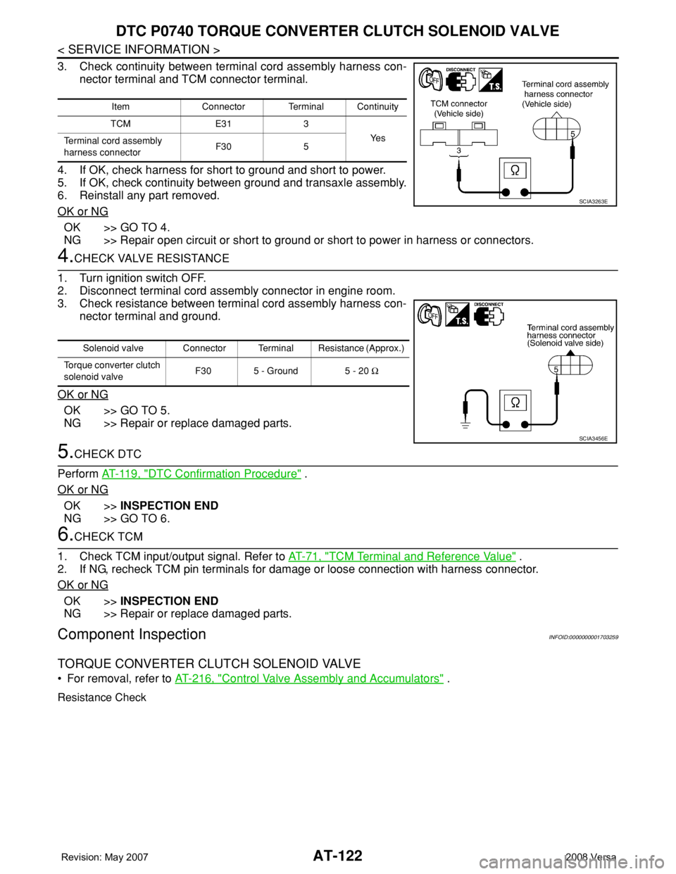
3. Check continuity between terminal cord assembly harness con-
nector terminal and TCM connector terminal.
4. If OK, check harness for short to ground and short to power.
5. If OK, check continuity between ground and transaxle assembly.
6. Reinstall any part removed.
OK or NG
OK >> GO TO 4.
NG >> Repair open circuit or short to ground or short to power in harness or connectors.
4.CHECK VALVE RESISTANCE
1. Turn ignition switch OFF.
2. Disconnect terminal cord assembly connector in engine room.
3. Check resistance between terminal cord assembly harness con-
nector terminal and ground.
OK or NG
OK >> GO TO 5.
NG >> Repair or replace damaged parts.
5.CHECK DTC
Perform AT-119, "
DTC Confirmation Procedure" .
OK or NG
OK >>INSPECTION END
NG >> GO TO 6.
6.CHECK TCM
1. Check TCM input/output signal. Refer to AT-71, "
TCM Terminal and Reference Value" .
2. If NG, recheck TCM pin terminals for damage or loose connection with harness connector.
OK or NG
OK >>INSPECTION END
NG >> Repair or replace damaged parts.
Component InspectionINFOID:0000000001703259
TORQUE CONVERTER CLUTCH SOLENOID VALVE
• For removal, refer to AT-216, "Control Valve Assembly and Accumulators" .
Resistance Check
Item Connector Terminal Continuity
TCM E31 3
Ye s
Terminal cord assembly
harness connectorF30 5
SCIA3263E
Solenoid valve Connector Terminal Resistance (Approx.)
Torque converter clutch
solenoid valveF30 5 - Ground 5 - 20 Ω
SCIA3456E