Page 2317 of 2771
TRANSAXLE ASSEMBLY
MT-29
< SERVICE INFORMATION >
D
E
F
G
H
I
J
K
L
MA
B
MT
N
O
P
36. Remove pinion gear (1) and pinion shaft (2) from clutch housing.
ASSEMBLY
1. Install pinion gear (1) and pinion shaft (2) into clutch housing.
2. Install two way connector (1) into clutch housing.
3. Install bushings (1) until they are flush with end face of clutch
housing using suitable tool (A).
PCIB1719E
PCIB1719E
PCIB1720E
PCIB1725E
Page 2318 of 2771
MT-30
< SERVICE INFORMATION >
TRANSAXLE ASSEMBLY
4. Install oil channel and mainshaft front bearing outer race into
clutch housing using Tool (A).
CAUTION:
Do not reuse oil channel.
5. Install input shaft oil seal (1) into clutch housing using Tool (A).
6. Install snap ring (1) and oil channel (2) onto transaxle case.
7. Install shim and mainshaft rear bearing outer race into transaxle
case using Tool (A).
8. Install bushings (1) into transaxle case using suitable tool (A).Tool number : KV38100200 ( — )
PCIB1724E
Tool number : ST33220000 ( — )
PCIB1721E
PCIB1729E
Tool number : KV38100200 ( — )
PCIB1728E
PCIB1727E
Page 2319 of 2771
TRANSAXLE ASSEMBLY
MT-31
< SERVICE INFORMATION >
D
E
F
G
H
I
J
K
L
MA
B
MT
N
O
P
9. Install oil gutter (1) onto transaxle case.
10. Install shift lever oil seal (1) and bushing (2) into transaxle case
using suitable tool (A).
11. Install control lever oil seal and bushings into transaxle case
using suitable tool.
12. Install shift finger (1) into transaxle case.
13. Install control lever (1) and then install retaining pin.
CAUTION:
Do not reuse retaining pin.
14. Install shim and differential side bearing outer race into transaxle
case using Tool (A).
PCIB1730E
PCIB1731E
PCIB1712E
PCIB1711E
Tool number : ST33400001 (J-26082)
PCIB1726E
Page 2320 of 2771
MT-32
< SERVICE INFORMATION >
TRANSAXLE ASSEMBLY
15. Install differential side bearing outer race into clutch housing
using Tool (A).
16. Install differential side oil seals (1) into clutch housing and tran-
saxle case using Tool (A).
17. Install magnet onto clutch housing.
18. Install final drive assembly into clutch housing.
19. Install input shaft assembly (1), mainshaft assembly (2) and 1st-
2nd fork rod assembly (3) into clutch housing.
20. Install spring washer located under the reverse idler shaft.
21. Install reverse gear assembly (1) according to the following:
a. Lift up the input shaft assembly (2) and mainshaft assembly (3).
b. Install reverse gear assembly (1) and reverse fork rod (4) to
clutch housing.
22. While lifting up fork rod (1), install 3rd-4th and 5th-6th fork rod
assembly to clutch housing. Tool number : KV38100200 ( — )
PCIB1722E
Tool number : KV38100300 (J-25523)
PCIB1732E
PCIB1702E
PCIB1701E
PCIB1700E
Page 2321 of 2771

TRANSAXLE ASSEMBLY
MT-33
< SERVICE INFORMATION >
D
E
F
G
H
I
J
K
L
MA
B
MT
N
O
P
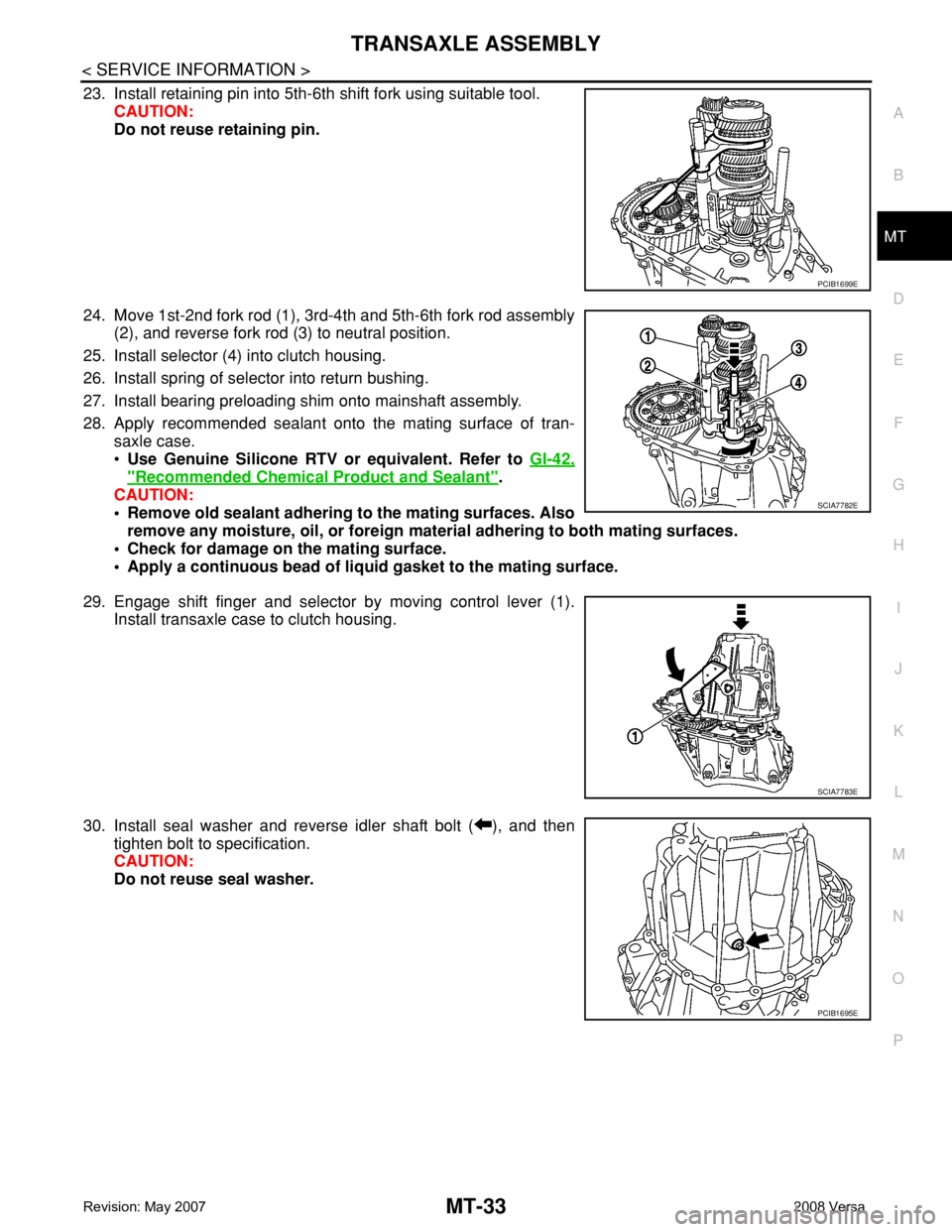
23. Install retaining pin into 5th-6th shift fork using suitable tool.
CAUTION:
Do not reuse retaining pin.
24. Move 1st-2nd fork rod (1), 3rd-4th and 5th-6th fork rod assembly
(2), and reverse fork rod (3) to neutral position.
25. Install selector (4) into clutch housing.
26. Install spring of selector into return bushing.
27. Install bearing preloading shim onto mainshaft assembly.
28. Apply recommended sealant onto the mating surface of tran-
saxle case.
•Use Genuine Silicone RTV or equivalent. Refer to GI-42,
"Recommended Chemical Product and Sealant".
CAUTION:
• Remove old sealant adhering to the mating surfaces. Also
remove any moisture, oil, or foreign material adhering to both mating surfaces.
• Check for damage on the mating surface.
• Apply a continuous bead of liquid gasket to the mating surface.
29. Engage shift finger and selector by moving control lever (1).
Install transaxle case to clutch housing.
30. Install seal washer and reverse idler shaft bolt ( ), and then
tighten bolt to specification.
CAUTION:
Do not reuse seal washer.
PCIB1699E
SCIA7782E
SCIA7783E
PCIB1695E
Page 2322 of 2771
MT-34
< SERVICE INFORMATION >
TRANSAXLE ASSEMBLY
31. Tighten bolts to specification.
32. Apply sealant to the threads of position switch (1). Then install it
into transaxle case and tighten to specification.
•Use Genuine Silicone RTV or equivalent.Refer to GI-42,
"Recommended Chemical Product and Sealant".
33. Install bracket (2), and tighten bolt to specification.
34. Install shift lever (3), and then install retaining pin using suitable
tool.
CAUTION:
Do not reuse retaining pin.
35. Install CSC onto clutch housing. Refer to CL-11, "
Removal and
Installation".
36. Install a new gasket onto drain plug, and then install it into clutch housing. Tighten drain plug to specifica-
tion.
37. Install a new gasket onto filler plug, and then install it into transaxle case. Tighten filler plug to specifica-
tion.
CAUTION:
• Do not reuse gasket.
• After oil is filled, tighten filler plug to specification.
PCIB1694E
SCIA7784E
Page 2334 of 2771
MT-46
< SERVICE INFORMATION >
FINAL DRIVE
FINAL DRIVE
Disassembly and AssemblyINFOID:0000000001703146
DISASSEMBLY
1. Remove differential side bearing inner race (clutch housing side)
(1) using Tool (A) and suitable tool.
2. Remove speedometer drive gear.
3. Remove final gear bolts (1), and then separate the final gear (2)
from differential case.
4. Remove differential side bearing inner race (transaxle case
side) (1) using suitable tool (A).
5. Remove lock ring (1) from differential case.
6. Remove pinion mate shaft, pinion mate gears, side gears and
thrust washer from differential case.
INSPECTION AFTER DISASSEMBLY
Gear, Washer, Shaft and Case
Tool number : ST33061000 (J-8107-2)
PCIB1767E
PCIB1766E
PCIB1765E
PCIB1764E