2008 NISSAN TIIDA Transaxle Assembly
[x] Cancel search: Transaxle AssemblyPage 1848 of 2771
FSU-14
< SERVICE INFORMATION >
TRANSVERSE LINK
TRANSVERSE LINK
Removal and InstallationINFOID:0000000001703727
REMOVAL
1. Remove front tires using power tool.
2. Remove transverse link ball joint nut and bolt. Then, remove transverse link from steering knuckle.
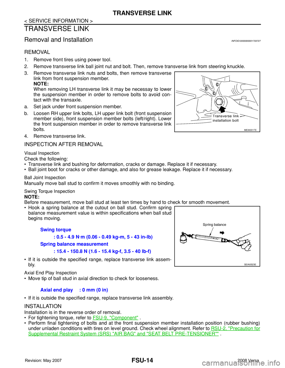
3. Remove transverse link nuts and bolts, then remove transverse
link from front suspension member.
NOTE:
When removing LH transverse link it may be necessay to lower
the suspension member in order to remove bolts to avoid con-
tact with the transaxle.
a. Set jack under front suspension member.
b. Loosen RH upper link bolts, LH upper link bolt (front suspension
member side), front suspension member bolts (left/right). Lower
the front suspension member in order to remove transverse link
bolts.
4. Remove transverse link.
INSPECTION AFTER REMOVAL
Visual Inspection
Check the following:
• Transverse link and bushing for deformation, cracks or damage. Replace it if necessary.
• Ball joint boot for cracks or other damage, and also for grease leakage. Replace it if necessary.
Ball Joint Inspection
Manually move ball stud to confirm it moves smoothly with no binding.
Swing Torque Inspection
NOTE:
Before measurement, move ball stud at least ten times by hand to check for smooth movement.
• Hook a spring balance at the cutout on ball stud. Confirm spring
balance measurement value is within specifications when ball stud
begins moving.
• If it is outside the specified range, replace transverse link assem-
bly.
Axial End Play Inspection
• Move tip of ball stud in axial direction to check for looseness.
• If it is outside the specified range, replace transverse link assembly.
INSTALLATION
Installation is in the reverse order of removal.
• For tightening torque, refer to FSU-9, "
Component" .
• Perform final tightening of bolts and at the front suspension member installation position (rubber bushing)
under unladen conditions with tires on level ground. Check wheel alignment. Refer to RSU-2, "
Precaution for
Supplemental Restraint System (SRS) "AIR BAG" and "SEAT BELT PRE-TENSIONER"" .
MEIA0017E
Swing torque
: 0.5 - 4.9 N·m (0.06 - 0.49 kg-m, 5 - 43 in-lb)
Spring balance measurement
: 15.4 - 150.8 N (1.6 - 15.4 kg-f, 3.5 - 40 lb-f)
SEIA0523E
Axial end play : 0 mm (0 in)
Page 1858 of 2771
HOW TO USE THIS MANUAL
GI-7
< SERVICE INFORMATION >
C
D
E
F
G
H
I
J
K
L
MB
GI
N
O
PHOW TO USE THIS MANUAL
DescriptionINFOID:0000000001702431
This volume explains “Removal, Disassembly, Installation, Inspection and Adjustment” and “Trouble Diag-
noses”.
Te r m sINFOID:0000000001702432
• The captions WARNING and CAUTION warn you of steps that must be followed to prevent personal injury
and/or damage to some part of the vehicle.
WARNING indicates the possibility of personal injury if instructions are not followed.
CAUTION indicates the possibility of component damage if instructions are not followed.
BOLD TYPED STATEMENTS except WARNING and CAUTION give you helpful information.
Standard value:Tolerance at inspection and adjustment.
Limit value:The maximum or minimum limit value that should not be exceeded at inspection and adjustment.
UnitsINFOID:0000000001702433
• The UNITS given in this manual are primarily expressed as the SI UNIT (International System of Unit), and
alternatively expressed in the metric system and in the yard/pound system.
Also with regard to tightening torque of bolts and nuts, there are descriptions both about range and about the
standard tightening torque.
“Example”
Range
Standard
ContentsINFOID:0000000001702434
•ALPHABETICAL INDEX is provided at the end of this manual so that you can rapidly find the item and page
you are searching for.
•A QUICK REFERENCE INDEX, a black tab (e.g. ) is provided on the first page. You can quickly find the
first page of each section by matching it to the section's black tab.
•THE CONTENTS are listed on the first page of each section.
•THE TITLE is indicated on the upper portion of each page and shows the part or system.
•THE PAGE NUMBER of each section consists of two or three letters which designate the particular section
and a number (e.g. “BR-5”).
•THE SMALL ILLUSTRATIONS show the important steps such as inspection, use of special tools, knacks of
work and hidden or tricky steps which are not shown in the previous large illustrations.
Assembly, inspection and adjustment procedures for the complicated units such as the automatic transaxle
or transmission, etc. are presented in a step-by-step format where necessary. Outer Socket Lock Nut : 59 - 78 N·m (6.0 - 8.0 kg-m, 43 - 58 ft-lb)
Drive Shaft Installation Bolt: 44.3 N·m (4.5 kg-m, 33 ft-lb)
Page 2280 of 2771
MA-20
< SERVICE INFORMATION >
CHASSIS AND BODY MAINTENANCE
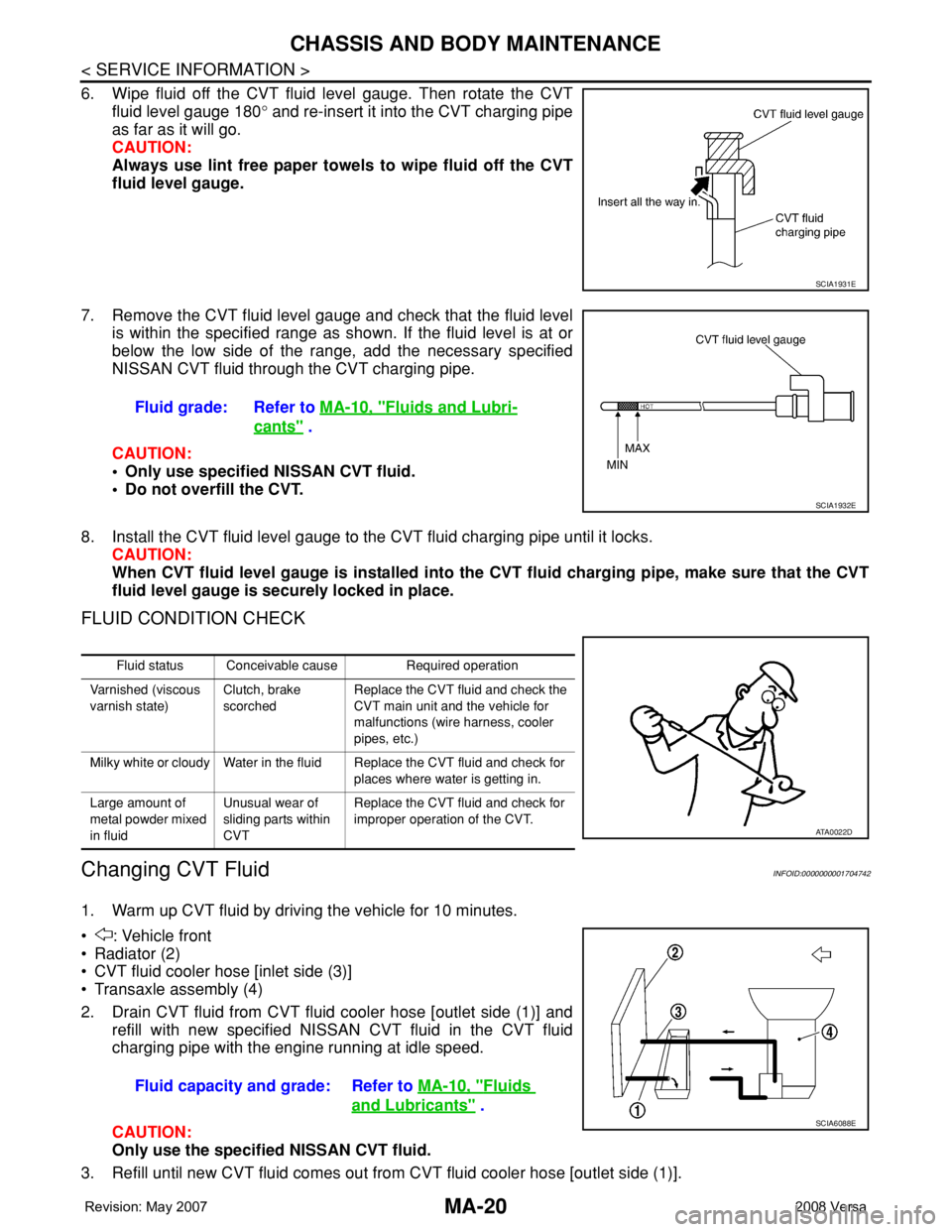
6. Wipe fluid off the CVT fluid level gauge. Then rotate the CVT
fluid level gauge 180° and re-insert it into the CVT charging pipe
as far as it will go.
CAUTION:
Always use lint free paper towels to wipe fluid off the CVT
fluid level gauge.
7. Remove the CVT fluid level gauge and check that the fluid level
is within the specified range as shown. If the fluid level is at or
below the low side of the range, add the necessary specified
NISSAN CVT fluid through the CVT charging pipe.
CAUTION:
• Only use specified NISSAN CVT fluid.
• Do not overfill the CVT.
8. Install the CVT fluid level gauge to the CVT fluid charging pipe until it locks.
CAUTION:
When CVT fluid level gauge is installed into the CVT fluid charging pipe, make sure that the CVT
fluid level gauge is securely locked in place.
FLUID CONDITION CHECK
Changing CVT FluidINFOID:0000000001704742
1. Warm up CVT fluid by driving the vehicle for 10 minutes.
• : Vehicle front
• Radiator (2)
• CVT fluid cooler hose [inlet side (3)]
• Transaxle assembly (4)
2. Drain CVT fluid from CVT fluid cooler hose [outlet side (1)] and
refill with new specified NISSAN CVT fluid in the CVT fluid
charging pipe with the engine running at idle speed.
CAUTION:
Only use the specified NISSAN CVT fluid.
3. Refill until new CVT fluid comes out from CVT fluid cooler hose [outlet side (1)].
SCIA1931E
Fluid grade: Refer to MA-10, "Fluids and Lubri-
cants" .
SCIA1932E
Fluid status Conceivable cause Required operation
Varnished (viscous
varnish state)Clutch, brake
scorchedReplace the CVT fluid and check the
CVT main unit and the vehicle for
malfunctions (wire harness, cooler
pipes, etc.)
Milky white or cloudy Water in the fluid Replace the CVT fluid and check for
places where water is getting in.
Large amount of
metal powder mixed
in fluidUnusual wear of
sliding parts within
CVTReplace the CVT fluid and check for
improper operation of the CVT.
ATA0022D
Fluid capacity and grade: Refer to MA-10, "Fluids
and Lubricants" .SCIA6088E
Page 2281 of 2771
CHASSIS AND BODY MAINTENANCE
MA-21
< SERVICE INFORMATION >
C
D
E
F
G
H
I
J
K
MA
B
MA
N
O
P
NOTE:
About 30 to 50% extra fluid will be required for this procedure.
4. Check fluid level and condition. Refer to MA-19, "
Checking CVT Fluid" .
CAUTION:
Delete CVT fluid deterioration date with CONSULT-II after changing CVT fluid. Refer to CVT-47,
"CONSULT-III Function (TRANSMISSION)" .
Checking Clutch Fluid Level and LeaksINFOID:0000000001704743
If fluid level is extremely low, check clutch system for leaks.
Checking Clutch SystemINFOID:0000000001704744
Check fluid lines and operating cylinder for improper attachment, cracks, damage, loose connections, chafing
and deterioration.
Checking M/T OilINFOID:0000000001704745
OIL LEAKAGE AND OIL LEVEL
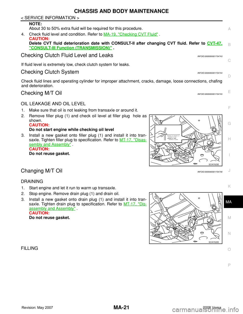
1. Make sure that oil is not leaking from transaxle or around it.
2. Remove filler plug (1) and check oil level at filler plug hole as
shown.
CAUTION:
Do not start engine while checking oil level
3. Install a new gasket onto filler plug (1) and install it into tran-
saxle. Tighten filler plug to specification. Refer to MT-17, "
Disas-
sembly and Assembly" .
CAUTION:
Do not reuse gasket.
Changing M/T OilINFOID:0000000001704746
DRAINING
1. Start engine and let it run to warm up transaxle.
2. Stop engine. Remove drain plug (1) and drain oil.
3. Install a new gasket onto drain plug (1) and install it into tran-
saxle. Tighten drain plug to specification. Refer to MT-17, "
Dis-
assembly and Assembly" .
CAUTION:
Do not reuse gasket.
FILLING
SCIA7623E
SCIA7622E
Page 2282 of 2771
MA-22
< SERVICE INFORMATION >
CHASSIS AND BODY MAINTENANCE
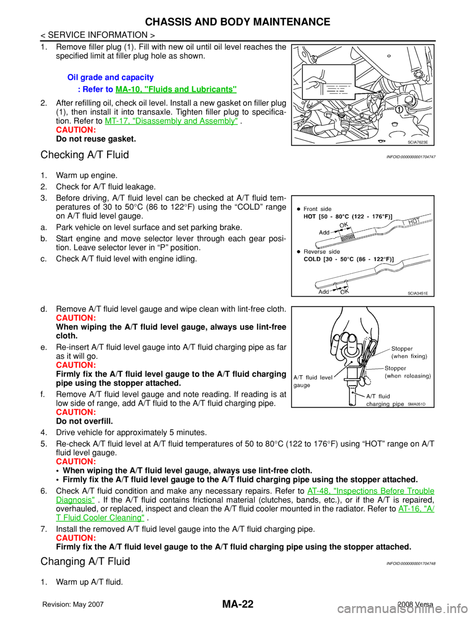
1. Remove filler plug (1). Fill with new oil until oil level reaches the
specified limit at filler plug hole as shown.
2. After refilling oil, check oil level. Install a new gasket on filler plug
(1), then install it into transaxle. Tighten filler plug to specifica-
tion. Refer to MT-17, "
Disassembly and Assembly" .
CAUTION:
Do not reuse gasket.
Checking A/T FluidINFOID:0000000001704747
1. Warm up engine.
2. Check for A/T fluid leakage.
3. Before driving, A/T fluid level can be checked at A/T fluid tem-
peratures of 30 to 50°C (86 to 122°F) using the “COLD” range
on A/T fluid level gauge.
a. Park vehicle on level surface and set parking brake.
b. Start engine and move selector lever through each gear posi-
tion. Leave selector lever in “P” position.
c. Check A/T fluid level with engine idling.
d. Remove A/T fluid level gauge and wipe clean with lint-free cloth.
CAUTION:
When wiping the A/T fluid level gauge, always use lint-free
cloth.
e. Re-insert A/T fluid level gauge into A/T fluid charging pipe as far
as it will go.
CAUTION:
Firmly fix the A/T fluid level gauge to the A/T fluid charging
pipe using the stopper attached.
f. Remove A/T fluid level gauge and note reading. If reading is at
low side of range, add A/T fluid to the A/T fluid charging pipe.
CAUTION:
Do not overfill.
4. Drive vehicle for approximately 5 minutes.
5. Re-check A/T fluid level at A/T fluid temperatures of 50 to 80°C (122 to 176°F) using “HOT” range on A/T
fluid level gauge.
CAUTION:
• When wiping the A/T fluid level gauge, always use lint-free cloth.
• Firmly fix the A/T fluid level gauge to the A/T fluid charging pipe using the stopper attached.
6. Check A/T fluid condition and make any necessary repairs. Refer to AT-48, "
Inspections Before Trouble
Diagnosis" . If the A/T fluid contains frictional material (clutches, bands, etc.), or if the A/T is repaired,
overhauled, or replaced, inspect and clean the A/T fluid cooler mounted in the radiator. Refer to AT-16, "
A/
T Fluid Cooler Cleaning" .
7. Install the removed A/T fluid level gauge into the A/T fluid charging pipe.
CAUTION:
Firmly fix the A/T fluid level gauge to the A/T fluid charging pipe using the stopper attached.
Changing A/T FluidINFOID:0000000001704748
1. Warm up A/T fluid.Oil grade and capacity
: Refer to MA-10, "
Fluids and Lubricants"
SCIA7623E
SCIA3451E
SMA051D
Page 2289 of 2771

MT-1
TRANSMISSION/TRANSAXLE
D
E
F
G
H
I
J
K
L
M
SECTION MT
A
B
MT
N
O
P
CONTENTS
MANUAL TRANSAXLE
SERVICE INFORMATION ............................2
PRECAUTIONS ...................................................2
Precaution for Supplemental Restraint System
(SRS) "AIR BAG" and "SEAT BELT PRE-TEN-
SIONER" ...................................................................
2
Precaution for Procedure without Cowl Top Cover ......2
Precaution .................................................................2
PREPARATION ...................................................3
Special Service Tool .................................................3
Commercial Service Tool ..........................................5
NOISE, VIBRATION AND HARSHNESS
(NVH) TROUBLESHOOTING .............................
7
NVH Troubleshooting Chart ......................................7
DESCRIPTION ....................................................8
Cross-Sectional View ................................................8
M/T OIL ...............................................................10
Changing M/T Oil ....................................................10
Checking M/T Oil .....................................................10
SIDE OIL SEAL ..................................................11
Removal and Installation .........................................11
POSITION SWITCH ............................................12
Checking .................................................................12
CONTROL LINKAGE ........................................13
Component of Control Device and Cable ................13
Removal and Installation .........................................13
AIR BREATHER HOSE ....................................15
Removal and Installation .........................................15
TRANSAXLE ASSEMBLY ................................16
Removal and Installation .........................................16
Disassembly and Assembly .....................................17
INPUT SHAFT AND GEARS ............................35
Disassembly and Assembly .....................................35
MAINSHAFT AND GEARS ...............................39
Disassembly and Assembly .....................................39
REVERSE IDLER SHAFT AND GEARS ..........44
Disassembly and Assembly .....................................44
FINAL DRIVE ....................................................46
Disassembly and Assembly .....................................46
SHIFT CONTROL ..............................................49
Inspection ................................................................49
SERVICE DATA AND SPECIFICATIONS
(SDS) .................................................................
50
General Specification ..............................................50
Page 2290 of 2771
MT-2
< SERVICE INFORMATION >
PRECAUTIONS
SERVICE INFORMATION
PRECAUTIONS
Precaution for Supplemental Restraint System (SRS) "AIR BAG" and "SEAT BELT
PRE-TENSIONER"
INFOID:0000000001703128
The Supplemental Restraint System such as “AIR BAG” and “SEAT BELT PRE-TENSIONER”, used along
with a front seat belt, helps to reduce the risk or severity of injury to the driver and front passenger for certain
types of collision. This system includes seat belt switch inputs and dual stage front air bag modules. The SRS
system uses the seat belt switches to determine the front air bag deployment, and may only deploy one front
air bag, depending on the severity of a collision and whether the front occupants are belted or unbelted.
Information necessary to service the system safely is included in the SRS and SB section of this Service Man-
ual.
WARNING:
• To avoid rendering the SRS inoperative, which could increase the risk of personal injury or death in
the event of a collision which would result in air bag inflation, all maintenance must be performed by
an authorized NISSAN/INFINITI dealer.
• Improper maintenance, including incorrect removal and installation of the SRS, can lead to personal
injury caused by unintentional activation of the system. For removal of Spiral Cable and Air Bag
Module, see the SRS section.
• Do not use electrical test equipment on any circuit related to the SRS unless instructed to in this
Service Manual. SRS wiring harnesses can be identified by yellow and/or orange harnesses or har-
ness connectors.
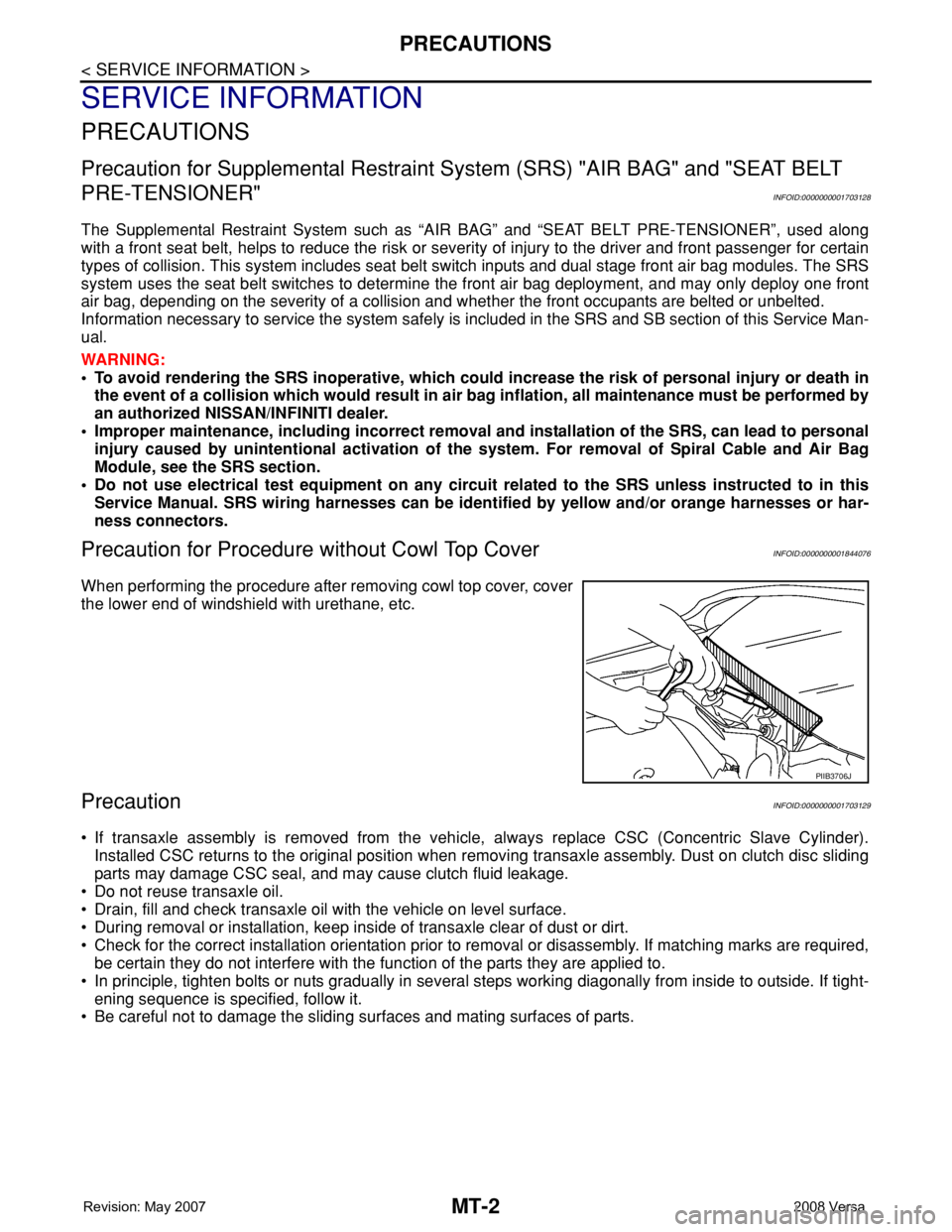
Precaution for Procedure without Cowl Top CoverINFOID:0000000001844076
When performing the procedure after removing cowl top cover, cover
the lower end of windshield with urethane, etc.
PrecautionINFOID:0000000001703129
• If transaxle assembly is removed from the vehicle, always replace CSC (Concentric Slave Cylinder).
Installed CSC returns to the original position when removing transaxle assembly. Dust on clutch disc sliding
parts may damage CSC seal, and may cause clutch fluid leakage.
• Do not reuse transaxle oil.
• Drain, fill and check transaxle oil with the vehicle on level surface.
• During removal or installation, keep inside of transaxle clear of dust or dirt.
• Check for the correct installation orientation prior to removal or disassembly. If matching marks are required,
be certain they do not interfere with the function of the parts they are applied to.
• In principle, tighten bolts or nuts gradually in several steps working diagonally from inside to outside. If tight-
ening sequence is specified, follow it.
• Be careful not to damage the sliding surfaces and mating surfaces of parts.
PIIB3706J
Page 2296 of 2771
MT-8
< SERVICE INFORMATION >
DESCRIPTION
DESCRIPTION
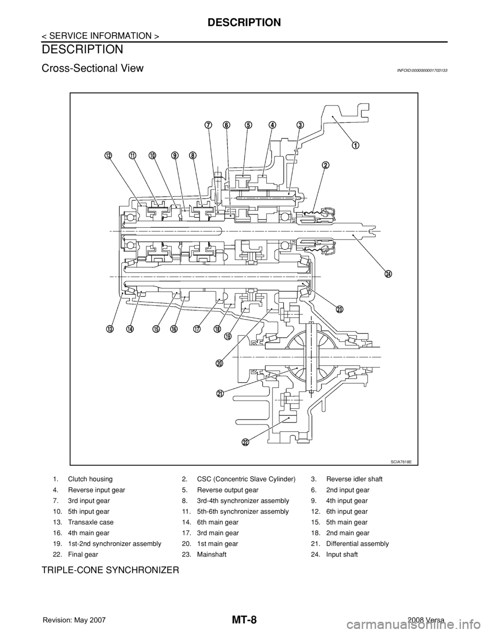
Cross-Sectional ViewINFOID:0000000001703133
TRIPLE-CONE SYNCHRONIZER
1. Clutch housing 2. CSC (Concentric Slave Cylinder) 3. Reverse idler shaft
4. Reverse input gear 5. Reverse output gear 6. 2nd input gear
7. 3rd input gear 8. 3rd-4th synchronizer assembly 9. 4th input gear
10. 5th input gear 11. 5th-6th synchronizer assembly 12. 6th input gear
13. Transaxle case 14. 6th main gear 15. 5th main gear
16. 4th main gear 17. 3rd main gear 18. 2nd main gear
19. 1st-2nd synchronizer assembly 20. 1st main gear 21. Differential assembly
22. Final gear 23. Mainshaft 24. Input shaft
SCIA7618E