2008 NISSAN TIIDA fuel pump
[x] Cancel search: fuel pumpPage 1025 of 2771
DI-4
< SERVICE INFORMATION >
COMBINATION METERS
COMBINATION METERS
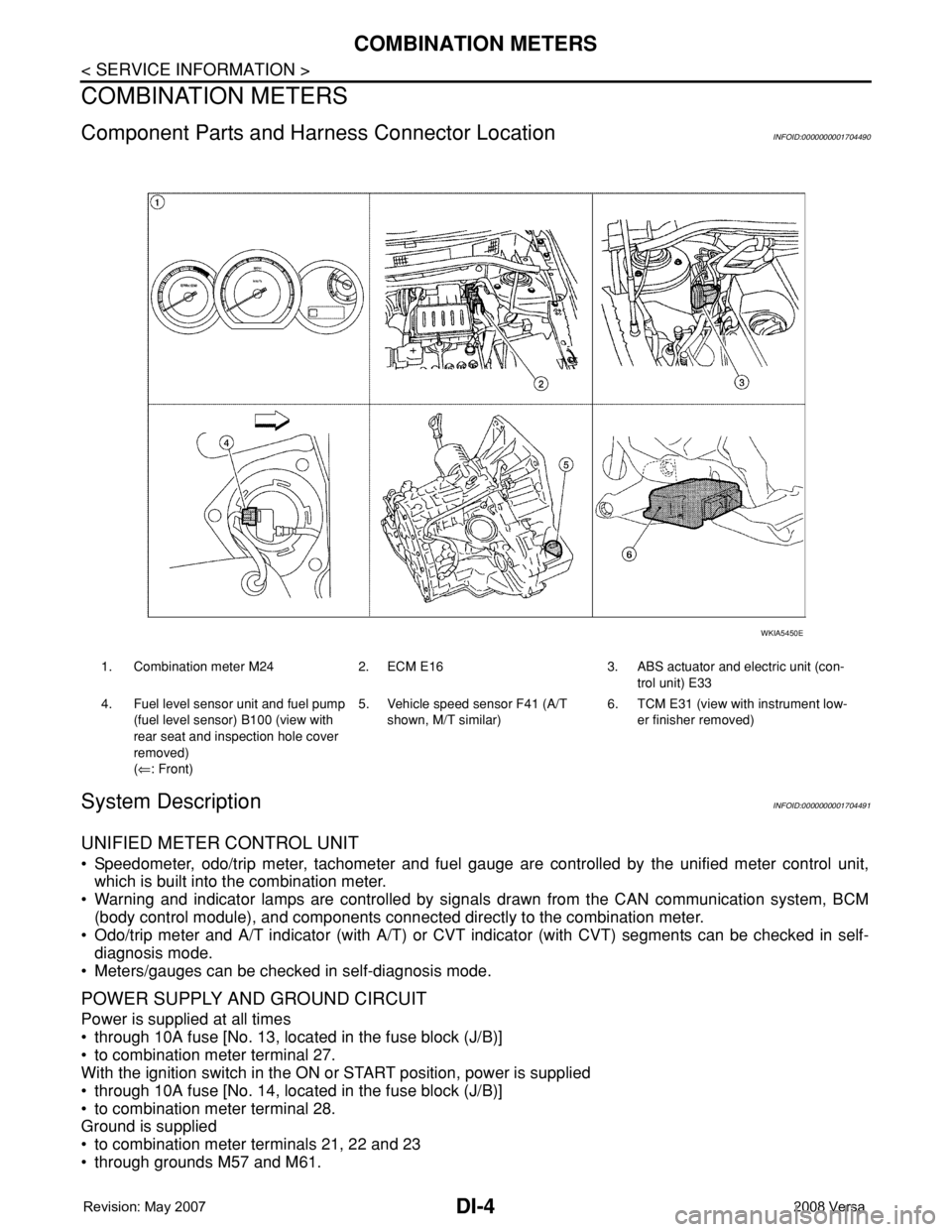
Component Parts and Harness Connector LocationINFOID:0000000001704490
System DescriptionINFOID:0000000001704491
UNIFIED METER CONTROL UNIT
• Speedometer, odo/trip meter, tachometer and fuel gauge are controlled by the unified meter control unit,
which is built into the combination meter.
• Warning and indicator lamps are controlled by signals drawn from the CAN communication system, BCM
(body control module), and components connected directly to the combination meter.
• Odo/trip meter and A/T indicator (with A/T) or CVT indicator (with CVT) segments can be checked in self-
diagnosis mode.
• Meters/gauges can be checked in self-diagnosis mode.
POWER SUPPLY AND GROUND CIRCUIT
Power is supplied at all times
• through 10A fuse [No. 13, located in the fuse block (J/B)]
• to combination meter terminal 27.
With the ignition switch in the ON or START position, power is supplied
• through 10A fuse [No. 14, located in the fuse block (J/B)]
• to combination meter terminal 28.
Ground is supplied
• to combination meter terminals 21, 22 and 23
• through grounds M57 and M61.
1. Combination meter M24 2. ECM E16 3. ABS actuator and electric unit (con-
trol unit) E33
4. Fuel level sensor unit and fuel pump
(fuel level sensor) B100 (view with
rear seat and inspection hole cover
removed)
(⇐: Front)5. Vehicle speed sensor F41 (A/T
shown, M/T similar)6. TCM E31 (view with instrument low-
er finisher removed)
WKIA5450E
Page 1026 of 2771
COMBINATION METERS
DI-5
< SERVICE INFORMATION >
C
D
E
F
G
H
I
J
L
MA
B
DI
N
O
P
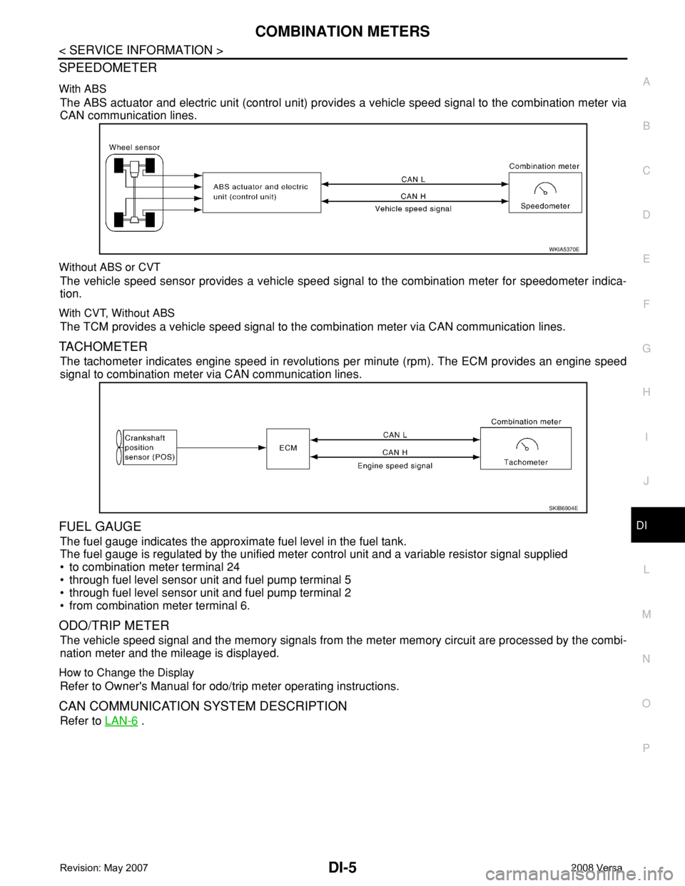
SPEEDOMETER
With ABS
The ABS actuator and electric unit (control unit) provides a vehicle speed signal to the combination meter via
CAN communication lines.
Without ABS or CVT
The vehicle speed sensor provides a vehicle speed signal to the combination meter for speedometer indica-
tion.
With CVT, Without ABS
The TCM provides a vehicle speed signal to the combination meter via CAN communication lines.
TACHOMETER
The tachometer indicates engine speed in revolutions per minute (rpm). The ECM provides an engine speed
signal to combination meter via CAN communication lines.
FUEL GAUGE
The fuel gauge indicates the approximate fuel level in the fuel tank.
The fuel gauge is regulated by the unified meter control unit and a variable resistor signal supplied
• to combination meter terminal 24
• through fuel level sensor unit and fuel pump terminal 5
• through fuel level sensor unit and fuel pump terminal 2
• from combination meter terminal 6.
ODO/TRIP METER
The vehicle speed signal and the memory signals from the meter memory circuit are processed by the combi-
nation meter and the mileage is displayed.
How to Change the Display
Refer to Owner's Manual for odo/trip meter operating instructions.
CAN COMMUNICATION SYSTEM DESCRIPTION
Refer to LAN-6 .
WKIA5370E
SKIB6904E
Page 1039 of 2771
DI-18
< SERVICE INFORMATION >
COMBINATION METERS
OK or NG
OK >> GO TO 2.
NG >> Replace combination meter. Refer to IP-11, "
Removal and Installation" .
2.CHECK HARNESS CONNECTOR
1. Turn ignition switch OFF.
2. Check combination meter and fuel level sensor unit terminals (meter-side and harness-side) for poor con-
nection.
OK or NG
OK >> GO TO 3.
NG >> Repair or replace terminals or connectors.
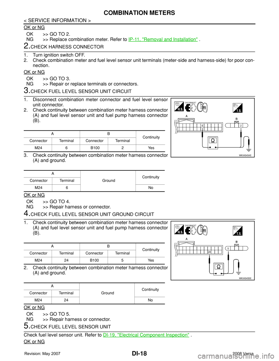
3.CHECK FUEL LEVEL SENSOR UNIT CIRCUIT
1. Disconnect combination meter connector and fuel level sensor
unit connector.
2. Check continuity between combination meter harness connector
(A) and fuel level sensor unit and fuel pump harness connector
(B).
3. Check continuity between combination meter harness connector
(A) and ground.
OK or NG
OK >> GO TO 4.
NG >> Repair harness or connector.
4.CHECK FUEL LEVEL SENSOR UNIT GROUND CIRCUIT
1. Check continuity between combination meter harness connector
(A) and fuel level sensor unit and fuel pump harness connector
(B).
2. Check continuity between combination meter harness connector
(A) and ground.
OK or NG
OK >> GO TO 5.
NG >> Repair harness or connector.
5.CHECK FUEL LEVEL SENSOR UNIT
Check fuel level sensor unit. Refer to DI-19, "
Electrical Component Inspection" .
OK or NG
AB
Continuity
Connector Terminal Connector Terminal
M24 6 B100 2 Yes
A
GroundContinuity
Connector Terminal
M24 6 No
WKIA5454E
AB
Continuity
Connector Terminal Connector Terminal
M24 24 B100 5 Yes
A
GroundContinuity
Connector Terminal
M24 24 No
WKIA5455E
Page 1040 of 2771
COMBINATION METERS
DI-19
< SERVICE INFORMATION >
C
D
E
F
G
H
I
J
L
MA
B
DI
N
O
P
OK >> Check fuel level sensor unit installation, and check whether the float arm interferes or binds with
any of the internal components in the fuel tank. Repair or replace malfunctioning part, if neces-
sary.
NG >> Replace fuel level sensor unit.
Fuel Gauge Fluctuates, Indicates Wrong Value, or VariesINFOID:0000000001704505
1.CHECK FUEL GAUGE FLUCTUATION
Test drive vehicle to see if gauge fluctuates only during driving or at the instant of stopping.
Does the indication value vary only during driving or at the at the instant of stopping?
YES >> The pointer fluctuation may be caused by fuel level change in the fuel tank. Condition is normal.
NO >> Ask the customer about the situation when the symptom occurs in detail, and perform the trouble
diagnosis.
Fuel Gauge Does Not Move to Full-positionINFOID:0000000001704506
1.OBSERVE FUEL GAUGE
Does it take a long time for the pointer to move to FULL position?
YES or NO
YES >> GO TO 2.
NO >> GO TO 3.
2.IDENTIFY FUELING CONDITION
Was the vehicle fueled with the ignition switch ON?
YES or NO
YES >> Be sure to fuel the vehicle with the ignition switch OFF. Otherwise, it will take a long time to move
to FULL position because of the characteristic of the fuel gauge.
NO >> GO TO 3.
3.OBSERVE VEHICLE POSITION
Is the vehicle parked on an incline?
YES or NO
YES >> Check the fuel level indication with vehicle on a level surface.
NO >> GO TO 4.
4.OBSERVE FUEL GAUGE POINTER
During driving, does the fuel gauge pointer move gradually toward EMPTY position?
YES or NO
YES >> Check the components. Refer to DI-19, "Electrical Component Inspection" .
NO >> The float arm may interfere or bind with any of the components in the fuel tank.
DTC [U1000] CAN Communication CircuitINFOID:0000000001704507
Symptom: Display CAN COMM CIRC [U1000] at the result of self-diagnosis for combination meter.
1.CHECK CAN COMMUNICATION
1. Select "SELF-DIAG RESULTS" mode for "METER/M&A" with CONSULT-III.
2. Print out CONSULT-III screen.
>> Go to "CAN SYSTEM". Refer to LAN-15, "
Trouble Diagnosis Flow Chart".
Electrical Component InspectionINFOID:0000000001704508
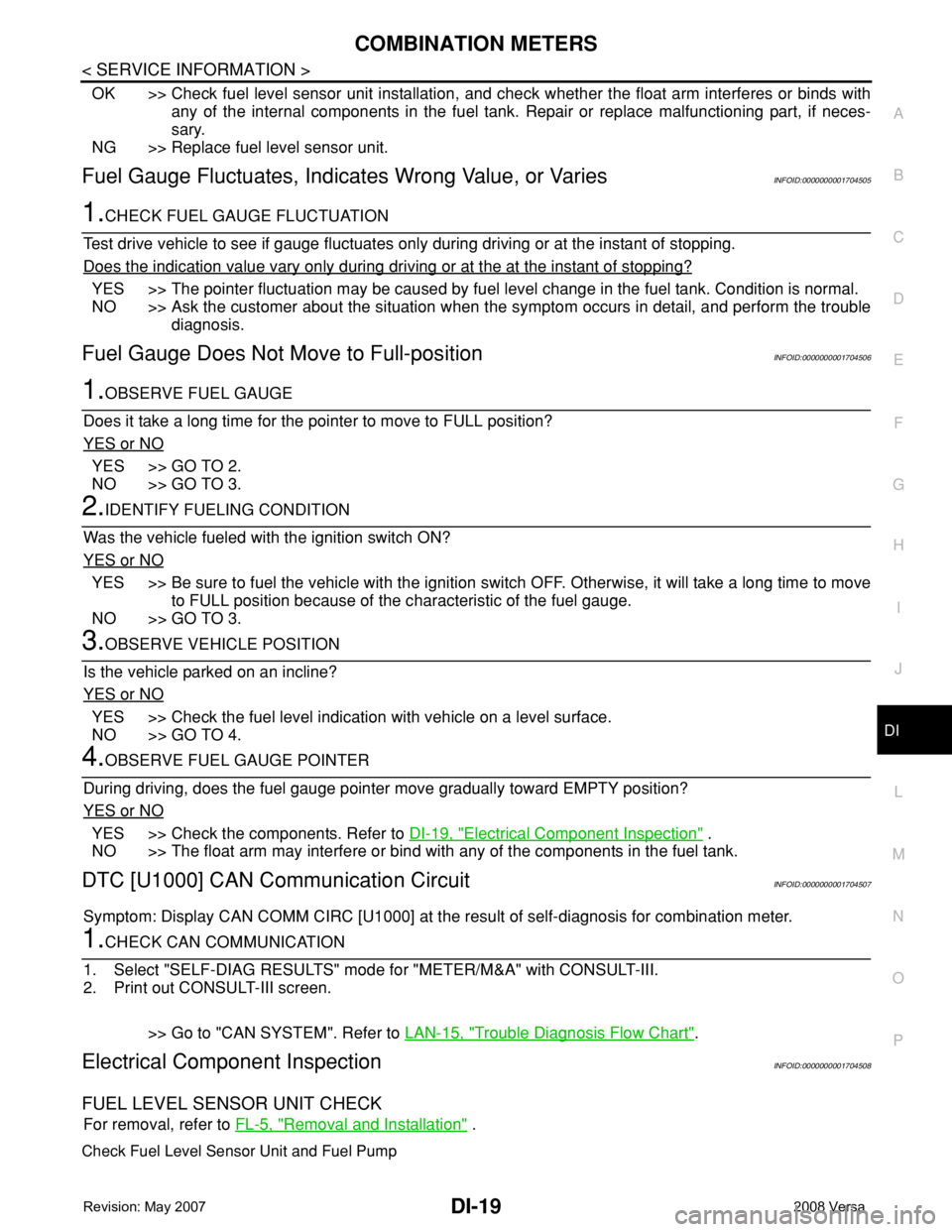
FUEL LEVEL SENSOR UNIT CHECK
For removal, refer to FL-5, "Removal and Installation" .
Check Fuel Level Sensor Unit and Fuel Pump
Page 1041 of 2771
DI-20
< SERVICE INFORMATION >
COMBINATION METERS
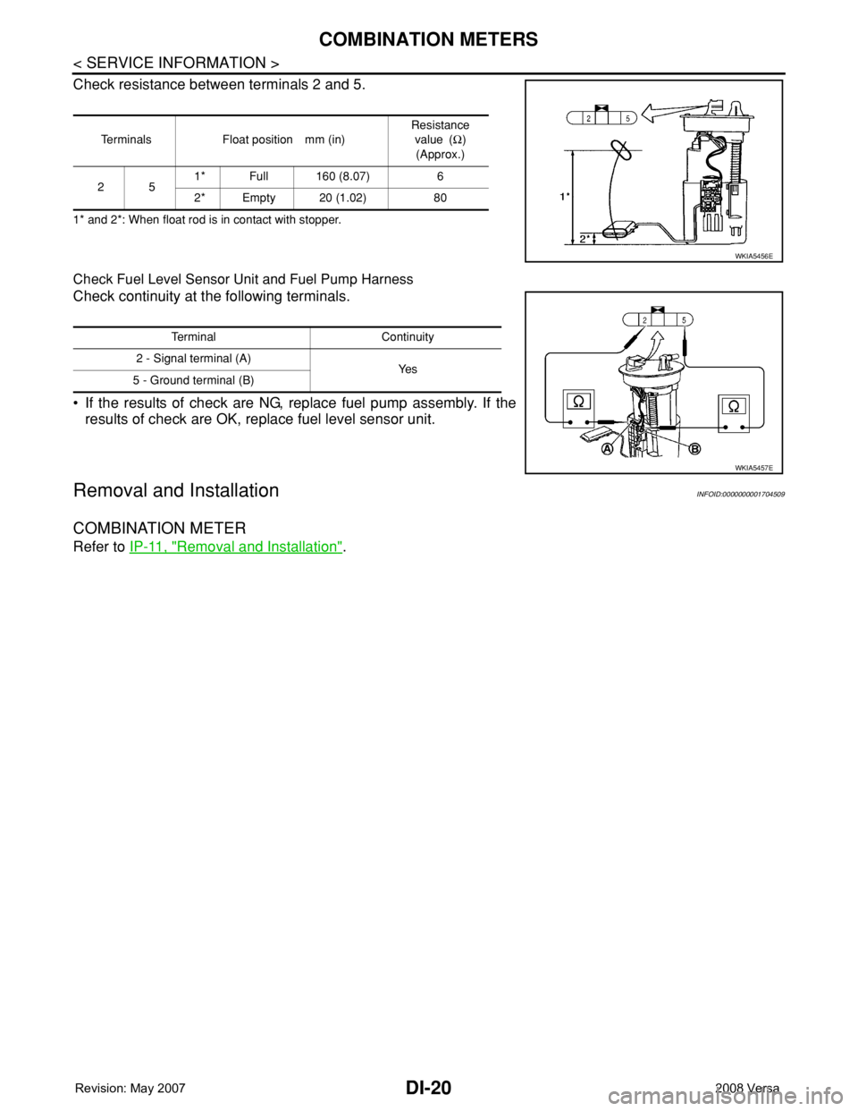
Check resistance between terminals 2 and 5.
1* and 2*: When float rod is in contact with stopper.
Check Fuel Level Sensor Unit and Fuel Pump Harness
Check continuity at the following terminals.
• If the results of check are NG, replace fuel pump assembly. If the
results of check are OK, replace fuel level sensor unit.
Removal and InstallationINFOID:0000000001704509
COMBINATION METER
Refer to IP-11, "Removal and Installation".
Terminals Float position mm (in)Resistance
value (Ω)
(Approx.)
251* Full 160 (8.07) 6
2* Empty 20 (1.02) 80
WKIA5456E
Terminal Continuity
2 - Signal terminal (A)
Ye s
5 - Ground terminal (B)
WKIA5457E
Page 1081 of 2771
EC-7
C
D
E
F
G
H
I
J
K
L
M
ECA
N
O
P
DTC P2119 ELECTRIC THROTTLE CON-
TROL ACTUATOR ...........................................
472
Component Description .........................................472
On Board Diagnosis Logic ....................................472
DTC Confirmation Procedure ................................472
Diagnosis Procedure .............................................473
DTC P2122, P2123 APP SENSOR ..................474
Component Description .........................................474
CONSULT-II Reference Value in Data Monitor
Mode .....................................................................
474
On Board Diagnosis Logic ....................................474
DTC Confirmation Procedure ................................474
Wiring Diagram .....................................................476
Diagnosis Procedure .............................................477
Component Inspection ..........................................479
Removal and Installation .......................................479
DTC P2127, P2128 APP SENSOR ..................480
Component Description .........................................480
CONSULT-II Reference Value in Data Monitor
Mode .....................................................................
480
On Board Diagnosis Logic ....................................480
DTC Confirmation Procedure ................................481
Wiring Diagram .....................................................482
Diagnosis Procedure .............................................483
Component Inspection ..........................................485
Removal and Installation .......................................486
DTC P2135 TP SENSOR .................................487
Component Description .........................................487
CONSULT-II Reference Value in Data Monitor
Mode .....................................................................
487
On Board Diagnosis Logic ....................................487
DTC Confirmation Procedure ................................487
Wiring Diagram .....................................................489
Diagnosis Procedure .............................................490
Component Inspection ..........................................492
Removal and Installation .......................................492
DTC P2138 APP SENSOR ...............................493
Component Description .........................................493
CONSULT-II Reference Value in Data Monitor
Mode .....................................................................
493
On Board Diagnosis Logic ....................................493
DTC Confirmation Procedure ................................494
Wiring Diagram .....................................................495
Diagnosis Procedure .............................................496
Component Inspection ..........................................499
Removal and Installation .......................................499
DTC P2A00 A/F SENSOR 1 .............................500
Component Description .........................................500
CONSULT-II Reference Value in Data Monitor
Mode .....................................................................
500
On Board Diagnosis Logic ....................................500
DTC Confirmation Procedure ................................500
Wiring Diagram .....................................................502
Diagnosis Procedure .............................................503
Removal and Installation .......................................507
ASCD BRAKE SWITCH ..................................508
Component Description .........................................508
CONSULT-II Reference Value in Data Monitor
Mode ......................................................................
508
Wiring Diagram ......................................................509
Diagnosis Procedure .............................................510
Component Inspection ...........................................514
ASCD INDICATOR ..........................................516
Component Description .........................................516
CONSULT-II Reference Value in Data Monitor
Mode ......................................................................
516
Wiring Diagram ......................................................517
Diagnosis Procedure .............................................517
ELECTRICAL LOAD SIGNAL ........................519
CONSULT-II Reference Value in Data Monitor
Mode ......................................................................
519
Diagnosis Procedure .............................................519
FUEL INJECTOR ............................................521
Component Description .........................................521
CONSULT-II Reference Value in Data Monitor
Mode ......................................................................
521
Wiring Diagram ......................................................522
Diagnosis Procedure .............................................523
Component Inspection ...........................................525
Removal and Installation .......................................525
FUEL PUMP ....................................................526
Description .............................................................526
CONSULT-II Reference Value in Data Monitor
Mode ......................................................................
526
Wiring Diagram ......................................................527
Diagnosis Procedure .............................................528
Component Inspection ...........................................530
Removal and Installation .......................................530
IGNITION SIGNAL ..........................................531
Component Description .........................................531
Wiring Diagram ......................................................532
Diagnosis Procedure .............................................535
Component Inspection ...........................................538
Removal and Installation .......................................540
REFRIGERANT PRESSURE SENSOR ..........541
Component Description .........................................541
Wiring Diagram ......................................................542
Diagnosis Procedure .............................................543
Removal and Installation .......................................545
MIL AND DATA LINK CONNECTOR .............546
Wiring Diagram ......................................................546
SERVICE DATA AND SPECIFICATIONS
(SDS) ...............................................................
548
Fuel Pressure ........................................................548
Idle Speed and Ignition Timing ..............................548
Calculated Load Value ..........................................548
Mass Air Flow Sensor ............................................548
Intake Air Temperature Sensor .............................548
Page 1082 of 2771

EC-8
Engine Coolant Temperature Sensor ....................548
Air Fuel Ratio (A/F) Sensor 1 Heater .....................549
Heated Oxygen sensor 2 Heater ...........................549
Crankshaft Position Sensor (POS) ........................549
Camshaft Position Sensor (PHASE) .....................549
Throttle Control Motor ...........................................549
Fuel Injector ..........................................................549
Fuel Pump .............................................................549
Page 1092 of 2771
EC-18
< SERVICE INFORMATION >
PRECAUTIONS
•Before replacing ECM, perform “ECM Terminals and Refer-
ence Value” inspection and make sure ECM functions prop-
erly. Refer to EC-102, "
ECM Terminal and Reference Value".
•Handle mass air flow sensor carefully to avoid damage.
•Do not disassemble mass air flow sensor.
•Do not clean mass air flow sensor with any type of detergent.
•Do not disassemble electric throttle control actuator.
•Even a slight leak in the air intake system can cause serious
incidents.
•Do not shock or jar the camshaft position sensor (PHASE),
crankshaft position sensor (POS).
•After performing each TROUBLE DIAGNOSIS, perform DTC
Confirmation Procedure or Overall Function Check.
The DTC should not be displayed in the DTC Confirmation
Procedure if the repair is completed. The Overall Function
Check should be a good result if the repair is completed.
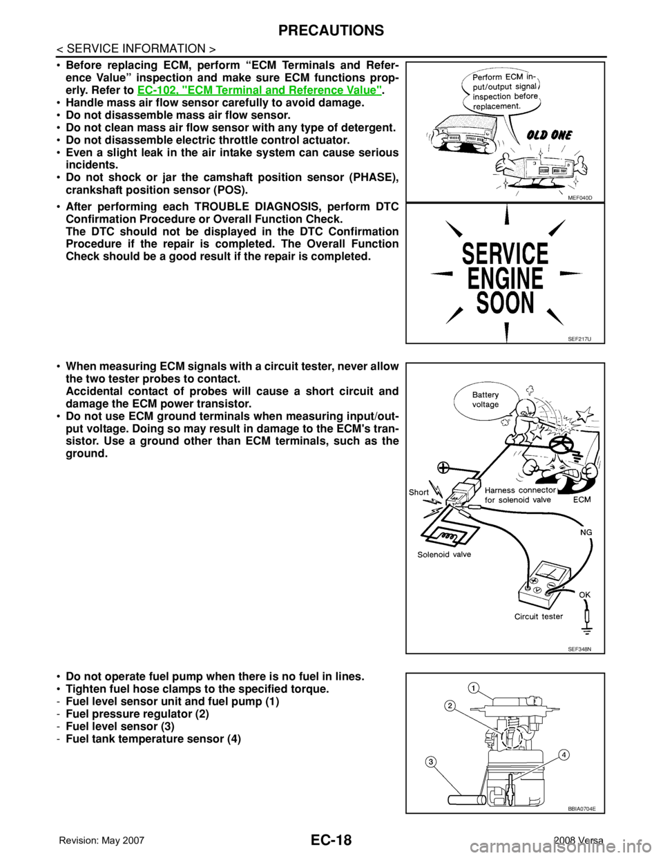
•When measuring ECM signals with a circuit tester, never allow
the two tester probes to contact.
Accidental contact of probes will cause a short circuit and
damage the ECM power transistor.
•Do not use ECM ground terminals when measuring input/out-
put voltage. Doing so may result in damage to the ECM's tran-
sistor. Use a ground other than ECM terminals, such as the
ground.
•Do not operate fuel pump when there is no fuel in lines.
•Tighten fuel hose clamps to the specified torque.
-Fuel level sensor unit and fuel pump (1)
-Fuel pressure regulator (2)
-Fuel level sensor (3)
-Fuel tank temperature sensor (4)
MEF040D
SEF217U
SEF348N
BBIA0704E