2008 NISSAN TIIDA fuel pump
[x] Cancel search: fuel pumpPage 1166 of 2771

EC-92
< SERVICE INFORMATION >
TROUBLE DIAGNOSIS
1 - 6: The numbers refer to the order of inspection.Cooling Radiator/Hose/Radiator filler cap
55555 55 45CO-11
Thermostat 5CO-17
Water pumpCO-16
Water galleryCO-7
Cooling fan
5CO-14
Coolant level (Low)/Contaminat-
ed coolantCO-8
NVIS (NISSAN Vehicle Immobilizer System-
NATS)11BL-210
SYMPTOM
Reference
page
HARD/NO START/RESTART (EXCP. HA)
ENGINE STALL
HESITATION/SURGING/FLAT SPOT
SPARK KNOCK/DETONATION
LACK OF POWER/POOR ACCELERATION
HIGH IDLE/LOW IDLE
ROUGH IDLE/HUNTING
IDLING VIBRATION
SLOW/NO RETURN TO IDLE
OVERHEATS/WATER TEMPERATURE HIGH
EXCESSIVE FUEL CONSUMPTION
EXCESSIVE OIL CONSUMPTION
BATTERY DEAD (UNDER CHARGE)
Warranty symptom code AA AB AC AD AE AF AG AH AJ AK AL AM HA
Page 1169 of 2771

TROUBLE DIAGNOSIS
EC-95
< SERVICE INFORMATION >
C
D
E
F
G
H
I
J
K
L
MA
EC
N
P O
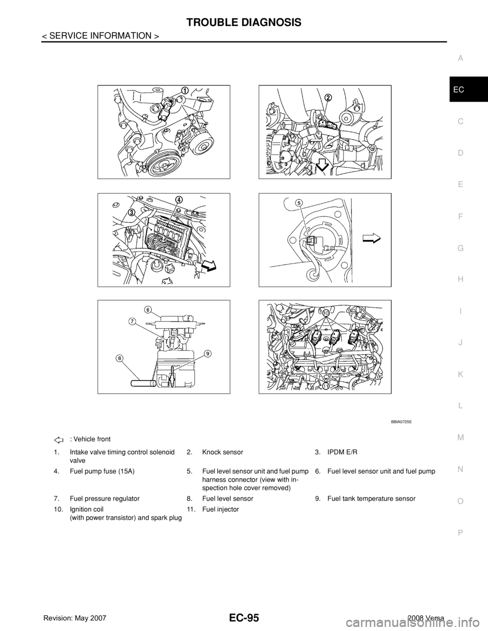
: Vehicle front
1. Intake valve timing control solenoid
valve2. Knock sensor 3. IPDM E/R
4. Fuel pump fuse (15A) 5. Fuel level sensor unit and fuel pump
harness connector (view with in-
spection hole cover removed)6. Fuel level sensor unit and fuel pump
7. Fuel pressure regulator 8. Fuel level sensor 9. Fuel tank temperature sensor
10. Ignition coil
(with power transistor) and spark plug11. Fuel injector
BBIA0725E
Page 1178 of 2771
![NISSAN TIIDA 2008 Service Repair Manual EC-104
< SERVICE INFORMATION >
TROUBLE DIAGNOSIS
15 Y Throttle control motor relay[Ignition switch: OFF]BATTERY VOLTAGE
(11 - 14V)
[Ignition switch: ON]0 - 1.0V
17
18
21
22R
LG
G
SBIgnition signal No NISSAN TIIDA 2008 Service Repair Manual EC-104
< SERVICE INFORMATION >
TROUBLE DIAGNOSIS
15 Y Throttle control motor relay[Ignition switch: OFF]BATTERY VOLTAGE
(11 - 14V)
[Ignition switch: ON]0 - 1.0V
17
18
21
22R
LG
G
SBIgnition signal No](/manual-img/5/57399/w960_57399-1177.png)
EC-104
< SERVICE INFORMATION >
TROUBLE DIAGNOSIS
15 Y Throttle control motor relay[Ignition switch: OFF]BATTERY VOLTAGE
(11 - 14V)
[Ignition switch: ON]0 - 1.0V
17
18
21
22R
LG
G
SBIgnition signal No. 1
Ignition signal No. 2
Ignition signal No. 4
Ignition signal No. 3[Engine is running]
•Warm-up condition
• Idle speed
NOTE:
The pulse cycle changes depending on rpm
at idle.0 - 0.3V
[Engine is running]
• Warm-up condition
• Engine speed: 2,500 rpm.0.2 - 0.5V
23 GR Fuel pump relay[Ignition switch: ON]
• For 1 second after turning ignition switch
ON
[Engine is running]0 - 1.0V
[Ignition switch: ON]
• More than 1 second after turning ignition
switch ONBATTERY VOLTAGE
(11 - 14V)
25
29
30
31V
Y
O
LFuel injector No. 4
Fuel injector No. 3
Fuel injector No. 2
Fuel injector No. 1[Engine is running]
•Warm-up condition
• Idle speed
NOTE:
The pulse cycle changes depending on rpm
at idle.BATTERY VOLTAGE
(11 - 14V)
[Engine is running]
•Warm-up condition
• Engine speed: 2,000 rpmBATTERY VOLTAGE
(11 - 14V)
28 WEVAP canister vent control
valve[Ignition switch: ON]BATTERY VOLTAGE
(11 - 14V)
32 PECM relay
(Self shut-off)[Engine is running]
[Ignition switch: OFF]
• For a few seconds after turning ignition
switch OFF0 - 1.0V
[Ignition switch: OFF]
• More than a few seconds after turning igni-
tion switch OFFBATTERY VOLTAGE
(11 - 14V) TERMI-
NAL
NO.WIRE
COLORITEM CONDITION DATA (DC Voltage)
PBIA9265J
PBIA9266J
PBIB0529E
PBIA4943J
Page 1185 of 2771

TROUBLE DIAGNOSIS
EC-111
< SERVICE INFORMATION >
C
D
E
F
G
H
I
J
K
L
MA
EC
N
P O
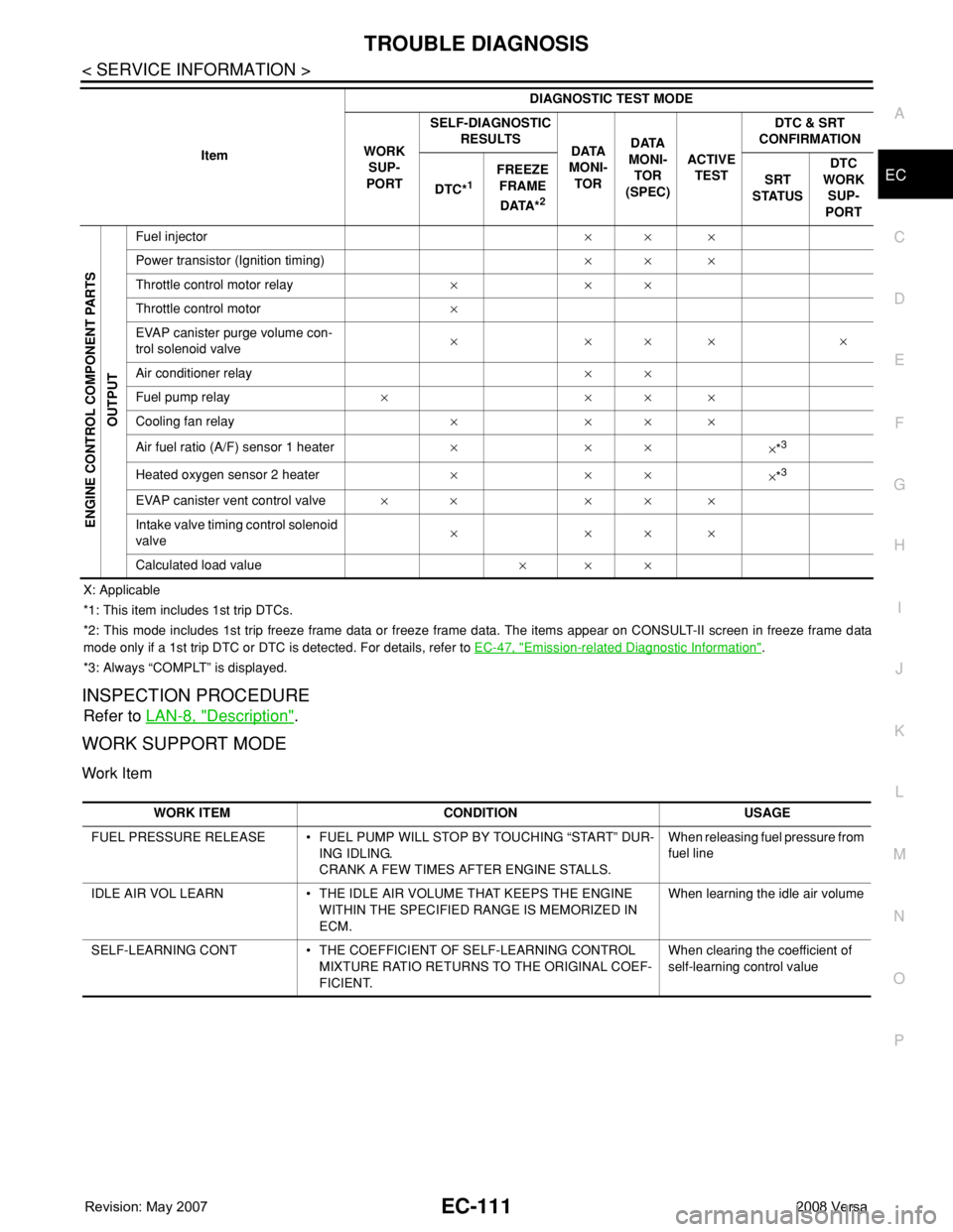
X: Applicable
*1: This item includes 1st trip DTCs.
*2: This mode includes 1st trip freeze frame data or freeze frame data. The items appear on CONSULT-II screen in freeze frame data
mode only if a 1st trip DTC or DTC is detected. For details, refer to EC-47, "
Emission-related Diagnostic Information".
*3: Always “COMPLT” is displayed.
INSPECTION PROCEDURE
Refer to LAN-8, "Description".
WORK SUPPORT MODE
Work Item
ENGINE CONTROL COMPONENT PARTS
OUTPUT
Fuel injector×× ×
Power transistor (Ignition timing)×× ×
Throttle control motor relay×××
Throttle control motor×
EVAP canister purge volume con-
trol solenoid valve×××××
Air conditioner relay××
Fuel pump relay××××
Cooling fan relay××××
Air fuel ratio (A/F) sensor 1 heater×××
×*
3
Heated oxygen sensor 2 heater×××
×*3
EVAP canister vent control valve×× ×××
Intake valve timing control solenoid
valve××××
Calculated load value××× ItemDIAGNOSTIC TEST MODE
WORK
SUP-
PORTSELF-DIAGNOSTIC
RESULTS
DATA
MONI-
TORDATA
MONI-
TOR
(SPEC)ACTIVE
TESTDTC & SRT
CONFIRMATION
DTC*
1 FREEZE
FRAME
DATA*
2
SRT
STATUSDTC
WORK
SUP-
PORT
WORK ITEM CONDITION USAGE
FUEL PRESSURE RELEASE • FUEL PUMP WILL STOP BY TOUCHING “START” DUR-
ING IDLING.
CRANK A FEW TIMES AFTER ENGINE STALLS.When releasing fuel pressure from
fuel line
IDLE AIR VOL LEARN • THE IDLE AIR VOLUME THAT KEEPS THE ENGINE
WITHIN THE SPECIFIED RANGE IS MEMORIZED IN
ECM.When learning the idle air volume
SELF-LEARNING CONT • THE COEFFICIENT OF SELF-LEARNING CONTROL
MIXTURE RATIO RETURNS TO THE ORIGINAL COEF-
FICIENT.When clearing the coefficient of
self-learning control value
Page 1189 of 2771
![NISSAN TIIDA 2008 Service Repair Manual TROUBLE DIAGNOSIS
EC-115
< SERVICE INFORMATION >
C
D
E
F
G
H
I
J
K
L
MA
EC
N
P OINT/V SOL (B1) [%]• The control value of the intake valve timing
control solenoid valve (determined by ECM ac-
cordin NISSAN TIIDA 2008 Service Repair Manual TROUBLE DIAGNOSIS
EC-115
< SERVICE INFORMATION >
C
D
E
F
G
H
I
J
K
L
MA
EC
N
P OINT/V SOL (B1) [%]• The control value of the intake valve timing
control solenoid valve (determined by ECM ac-
cordin](/manual-img/5/57399/w960_57399-1188.png)
TROUBLE DIAGNOSIS
EC-115
< SERVICE INFORMATION >
C
D
E
F
G
H
I
J
K
L
MA
EC
N
P OINT/V SOL (B1) [%]• The control value of the intake valve timing
control solenoid valve (determined by ECM ac-
cording to the input signal) is indicated.
• The advance angle becomes larger as the val-
ue increases
AIR COND RLY
[ON/OFF]ו The air conditioner relay control condition (de-
termined by ECM according to the input sig-
nals) is indicated.
FUEL PUMP RLY
[ON/OFF]ו Indicates the fuel pump relay control condition
determined by ECM according to the input sig-
nals.
VENT CONT/V [ON/
OFF]• The control condition of the EVAP canister vent
control valve (determined by ECM according to
the input signals) is indicated.
ON: Closed
OFF: Open
THRTL RELAY
[ON/OFF]ו Indicates the throttle control motor relay control
condition determined by the ECM according to
the input signals.
COOLING FAN
[HI/LOW/OFF]ו Indicates the condition of the cooling fan (de-
termined by ECM according to the input sig-
nals).
HI: High speed operation
LOW: Low speed operation
OFF: Stop
HO2S2 HTR (B1)
[ON/OFF]• Indicates [ON/OFF] condition of heated oxygen
sensor 2 heater determined by ECM according
to the input signals.
I/P PULLY SPD
[rpm]• Indicates the engine speed computed from the
turbine revolution sensor signal.
VEHICLE SPEED
[km/h] or [MPH]ו The vehicle speed computed from the vehicle
speed signal sent from TCM is displayed.
IDL A/V LEARN
[YET/CMPLT]• Display the condition of idle air volume learning
YET: Idle Air Volume Learning has not been
performed yet.
CMPLT: Idle Air Volume Learning has already
been performed successfully.
TRVL AFTER MIL
[km] or [mile]• Distance traveled while MIL is activated.
A/F S1 HTR (B1) [%]• Indicates A/F sensor 1 heater control value
computed by ECM according to the input sig-
nals.
• The current flow to the heater becomes larger
as the value increases.
AC PRESS SEN [V]ו The signal voltage from the refrigerant pres-
sure sensor is displayed.
VHCL SPEED SE
[km/h] or [MPH]• The vehicle speed computed from the vehicle
speed signal sent from TCM is displayed.
SET VHCL SPD
[km/h] or [MPH]• The preset vehicle speed is displayed.
MAIN SW
[ON/OFF]• Indicates [ON/OFF] condition from MAIN
switch signal.
CANCEL SW
[ON/OFF]• Indicates [ON/OFF] condition from CANCEL
switch signal. Monitored item [Unit]ECM IN-
PUT SIG-
NALSMAIN
SIG-
NALSDescription Remarks
Page 1191 of 2771

TROUBLE DIAGNOSIS
EC-117
< SERVICE INFORMATION >
C
D
E
F
G
H
I
J
K
L
MA
EC
N
P O
NOTE:
Any monitored item that does not match the vehicle being diagnosed is deleted from the display automatically.
ACTIVE TEST MODE
Test Item
Monitored item [Unit]ECM
input
signalsMain
signalsDescription Remarks
ENG SPEED [rpm]×ו Indicates the engine speed computed
from the signal of the crankshaft position
sensor (POS) and camshaft position
sensor (PHASE).
MAS A/F SE-B1 [V]×ו The signal voltage of the mass air flow
sensor specification is displayed.• When engine is running specification
range is indicated.
B/FUEL SCHDL
[msec]ו “Base fuel schedule” indicates the fuel in-
jection pulse width programmed into
ECM, prior to any learned on board cor-
rection.• When engine is running specification
range is indicated.
A/F ALPHA-B1 [%]ו The mean value of the air-fuel ratio feed-
back correction factor per cycle is indi-
cated.• When engine is running specification
range is indicated.
• This data also includes the data for the
air-fuel ratio learning control.
TEST ITEM CONDITION JUDGEMENT CHECK ITEM (REMEDY)
FUEL INJEC-
TION• Engine: Return to the original
trouble condition
• Change the amount of fuel injec-
tion using CONSULT-II.If trouble symptom disappears, see
CHECK ITEM.• Harness and connectors
• Fuel injector
• Air fuel ratio (A/F) sensor 1
IGNITION TIM-
ING• Engine: Return to the original
trouble condition
• Timing light: Set
• Retard the ignition timing using
CONSULT-II.If trouble symptom disappears, see
CHECK ITEM.• Perform Idle Air Volume Learning.
POWER BAL-
ANCE• Engine: After warming up, idle the
engine.
• A/C switch OFF
• Shift lever: P or N (A/T, CVT),
Neutral (M/T)
• Cut off each fuel injector signal
one at a time using CONSULT-II.Engine runs rough or dies.• Harness and connectors
• Compression
• Fuel injector
• Power transistor
•Spark plug
• Ignition coil
COOLING FAN*• Ignition switch: ON
• Turn the cooling fan “LOW”, “HI”
and “OFF” with CONSULT-II.Cooling fan moves and stops.• Harness and connectors
• Cooling fan relay
• Cooling fan motor
ENG COOLANT
TEMP• Engine: Return to the original
trouble condition
• Change the engine coolant tem-
perature using CONSULT-II.If trouble symptom disappears, see
CHECK ITEM.• Harness and connectors
• Engine coolant temperature sen-
sor
• Fuel injector
FUEL PUMP RE-
LAY• Ignition switch: ON
(Engine stopped)
• Turn the fuel pump relay ON and
OFF using CONSULT-II and lis-
ten to operating sound.Fuel pump relay makes the operat-
ing sound.• Harness and connectors
• Fuel pump relay
PURG VOL
CONT/V• Engine: After warming up, run en-
gine at 1,500 rpm.
• Change the EVAP canister purge
volume control solenoid valve
opening percent using CON-
SULT-II.Engine speed changes according to
the opening percent.• Harness and connectors
• EVAP canister purge volume con-
trol solenoid valve
Page 1197 of 2771

TROUBLE DIAGNOSIS
EC-123
< SERVICE INFORMATION >
C
D
E
F
G
H
I
J
K
L
MA
EC
N
P O
INT/V SOL (B1)• Engine: After warming up
• Air conditioner switch: OFF
• Shift lever: P or N (A/T, CVT),
Neutral (M/T)
•No loadIdle 0% - 2%
When revving engine up to 2,000 rpm
quicklyApprox. 0% - 90%
AIR COND RLY• Engine: After warming up, idle the
engineAir conditioner switch: OFF OFF
Air conditioner switch: ON
(Compressor operates)ON
FUEL PUMP RLY• For 1 second after turning ignition switch ON
• Engine running or crankingON
• Except above conditions OFF
VENT CONT/V • Ignition switch: ON OFF
THRTL RELAY • Ignition switch: ON ON
COOLING FAN• Engine: After warming up, idle the
engine
• Air conditioner switch: OFFEngine coolant temperature: 97°C
(207°F) or lessOFF
Engine coolant temperature: Between
98°C (208°F) and 99°C (210°F)LOW
Engine coolant temperature: 100°C
(212°F) or moreHIGH
HO2S2 HTR (B1)• Below 3,600 rpm after the following conditions are met.
- Engine: After warming up
- Keeping the engine speed between 3,500 and 4,000 rpm for 1 minute and
at idle for 1 minute under no loadON
• Engine speed: Above 3,600 rpm OFF
I/P PULLY SPD • Vehicle speed: More than 20 km/h (12 MPH)Almost the same speed as the
tachometer indication
VEHICLE SPEED• Turn drive wheels and compare CONSULT-II value with the speedometer
indication.Almost the same speed as the
speedometer indication
TRVL AFTER MIL • Ignition switch: ONVehicle has traveled after MIL has
turned ON.0 - 65,535 km
(0 - 40,723 mile)
A/F S1 HTR (B1)• Engine: After warming up, idle the engine
(More than 140 seconds after starting engine.)4 - 100%
AC PRESS SEN• Engine: Idle
• Air conditioner switch: ON (Compressor operates)1.0 - 4.0V
VHCL SPEED SE• Turn drive wheels and compare speedometer indication with the CONSULT-
II value.Almost the same speed as the
speedometer indication
SET VHCL SPD • Engine: Running ASCD: OperatingThe preset vehicle speed is
displayed.
MAIN SW • Ignition switch: ONMAIN switch: Pressed ON
MAIN switch: Released OFF
CANCEL SW • Ignition switch: ONCANCEL switch: Pressed ON
CANCEL switch: Released OFF
RESUME/ACC SW • Ignition switch: ONRESUME/ACCELERATE switch:
PressedON
RESUME/ACCELERATE switch: Re-
leased
OFF
SET SW • Ignition switch: ONSET/COAST switch: Pressed ON
SET/COAST switch: Released OFF MONITOR ITEM CONDITION SPECIFICATION
Page 1205 of 2771

TROUBLE DIAGNOSIS - SPECIFICATION VALUE
EC-131
< SERVICE INFORMATION >
C
D
E
F
G
H
I
J
K
L
MA
EC
N
P O
6.CHECK FUEL PRESSURE
Check fuel pressure. (Refer to EC-78, "
Fuel Pressure Check".)
OK or NG
OK >> GO TO 9.
NG (Fuel pressure is too high)>>Replace fuel pressure regulator, refer to EC-78, "
Fuel Pressure Check". GO
TO 8.
NG (Fuel pressure is too low)>>GO TO 7.
7.DETECT MALFUNCTIONING PART
1. Check the following.
- Clogged and bent fuel hose and fuel tube
- Clogged fuel filter
- Fuel pump and its circuit (Refer to EC-526
.)
2. If NG, repair or replace the malfunctioning part. (Refer to EC-78, "
Fuel Pressure Check".)
If OK, replace fuel pressure regulator.
>> GO TO 8.
8.CHECK “A/F ALPHA-B1”
1. Start engine.
2. Select “A/F ALPHA-B1” in “DATA MONITOR (SPEC)” mode, and make sure that the indication is within
the SP value.
OK or NG
OK >>INSPECTION END
NG >> GO TO 9.
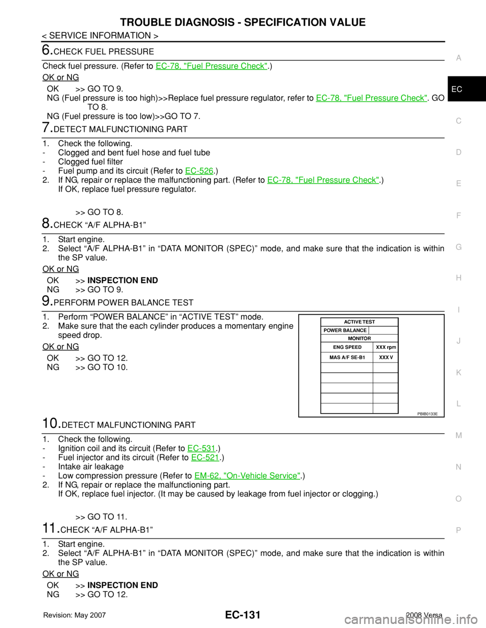
9.PERFORM POWER BALANCE TEST
1. Perform “POWER BALANCE” in “ACTIVE TEST” mode.
2. Make sure that the each cylinder produces a momentary engine
speed drop.
OK or NG
OK >> GO TO 12.
NG >> GO TO 10.
10.DETECT MALFUNCTIONING PART
1. Check the following.
- Ignition coil and its circuit (Refer to EC-531
.)
- Fuel injector and its circuit (Refer to EC-521
.)
- Intake air leakage
- Low compression pressure (Refer to EM-62, "
On-Vehicle Service".)
2. If NG, repair or replace the malfunctioning part.
If OK, replace fuel injector. (It may be caused by leakage from fuel injector or clogging.)
>> GO TO 11.
11 .CHECK “A/F ALPHA-B1”
1. Start engine.
2. Select “A/F ALPHA-B1” in “DATA MONITOR (SPEC)” mode, and make sure that the indication is within
the SP value.
OK or NG
OK >>INSPECTION END
NG >> GO TO 12.
PBIB0133E