2008 NISSAN TIIDA fuel pump
[x] Cancel search: fuel pumpPage 1462 of 2771
EC-388
< SERVICE INFORMATION >
DTC P0461 FUEL LEVEL SENSOR
5. Turn ignition switch OFF and wait at least 10 seconds then turn
ON.
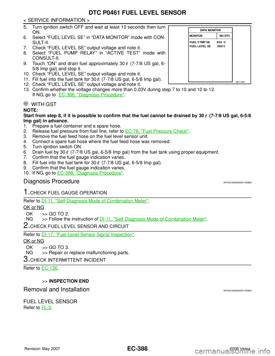
6. Select “FUEL LEVEL SE” in “DATA MONITOR” mode with CON-
SULT-II.
7. Check “FUEL LEVEL SE” output voltage and note it.
8. Select “FUEL PUMP RELAY” in “ACTIVE TEST” mode with
CONSULT-II.
9. Touch “ON” and drain fuel approximately 30 (7-7/8 US gal, 6-
5/8 Imp gal) and stop it.
10. Check “FUEL LEVEL SE” output voltage and note it.
11. Fill fuel into the fuel tank for 30 (7-7/8 US gal, 6-5/8 Imp gal).
12. Check “FUEL LEVEL SE” output voltage and note it.
13. Confirm whether the voltage changes more than 0.03V during step 7 to 10 and 10 to 12.
If NG, go to EC-388, "
Diagnosis Procedure".
WITH GST
NOTE:
Start from step 8, if it is possible to confirm that the fuel cannot be drained by 30 (7-7/8 US gal, 6-5/8
Imp gal) in advance.
1. Prepare a fuel container and a spare hose.
2. Release fuel pressure from fuel line, refer to EC-78, "
Fuel Pressure Check".
3. Remove the fuel feed hose on the fuel level sensor unit.
4. Connect a spare fuel hose where the fuel feed hose was removed.
5. Turn ignition switch ON.
6. Drain fuel by 30 (7-7/8 US gal, 6-5/8 Imp gal) from the fuel tank using proper equipment.
7. Confirm that the fuel gauge indication varies.
8. Fill fuel into the fuel tank for 30 (7-7/8 US gal, 6-5/8 Imp gal).
9. Confirm that the fuel gauge indication varies.
10. If NG, go to EC-388, "
Diagnosis Procedure".
Diagnosis ProcedureINFOID:0000000001702893
1.CHECK FUEL GAUGE OPERATION
Refer to DI-11, "
Self-Diagnosis Mode of Combination Meter".
OK or NG
OK >> GO TO 2.
NG >> Follow the instruction of DI-11, "
Self-Diagnosis Mode of Combination Meter".
2.CHECK FUEL LEVEL SENSOR AND CIRCUIT
Refer to DI-17, "
Fuel Level Sensor Signal Inspection".
OK or NG
OK >> GO TO 3.
NG >> Repair or replace malfunctioning parts.
3.CHECK INTERMITTENT INCIDENT
Refer to EC-136
.
>>INSPECTION END
Removal and InstallationINFOID:0000000001702894
FUEL LEVEL SENSOR
Refer to FL-5.
SEF195Y
Page 1463 of 2771
DTC P0462, P0463 FUEL LEVEL SENSOR
EC-389
< SERVICE INFORMATION >
C
D
E
F
G
H
I
J
K
L
MA
EC
N
P O
DTC P0462, P0463 FUEL LEVEL SENSOR
Component DescriptionINFOID:0000000001702895
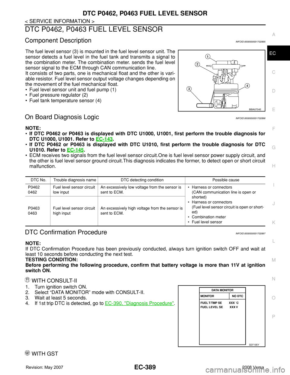
The fuel level sensor (3) is mounted in the fuel level sensor unit. The
sensor detects a fuel level in the fuel tank and transmits a signal to
the combination meter. The combination meter. sends the fuel level
sensor signal to the ECM through CAN communication line.
It consists of two parts, one is mechanical float and the other is vari-
able resistor. Fuel level sensor output voltage changes depending on
the movement of the fuel mechanical float.
• Fuel level sensor unit and fuel pump (1)
• Fuel pressure regulator (2)
• Fuel tank temperature sensor (4)
On Board Diagnosis LogicINFOID:0000000001702896
NOTE:
•If DTC P0462 or P0463 is displayed with DTC U1000, U1001, first perform the trouble diagnosis for
DTC U1000, U1001. Refer to EC-143
.
•If DTC P0462 or P0463 is displayed with DTC U1010, first perform the trouble diagnosis for DTC
U1010. Refer to EC-145
.
• ECM receives two signals from the fuel level sensor circuit.One is fuel level sensor power supply circuit, and
the other is fuel level sensor ground circuit.This diagnosis indicates the former, to detect open or short circuit
malfunction.
DTC Confirmation ProcedureINFOID:0000000001702897
NOTE:
If DTC Confirmation Procedure has been previously conducted, always turn ignition switch OFF and wait at
least 10 seconds before conducting the next test.
TESTING CONDITION:
Before performing the following procedure, confirm that battery voltage is more than 11V at ignition
switch ON.
WITH CONSULT-II
1. Turn ignition switch ON.
2. Select “DATA MONITOR” mode with CONSULT-II.
3. Wait at least 5 seconds.
4. If 1st trip DTC is detected, go to EC-390, "
Diagnosis Procedure".
WITH GST
BBIA0704E
DTC No. Trouble diagnosis name DTC detecting condition Possible cause
P0462
0462Fuel level sensor circuit
low inputAn excessively low voltage from the sensor is
sent to ECM.• Harness or connectors
(CAN communication line is open or
shorted)
• Harness or connectors
(Fuel level sensor circuit is open or short-
ed)
• Combination meter
• Fuel level sensor P0463
0463Fuel level sensor circuit
high inputAn excessively high voltage from the sensor is
sent to ECM.
SEF195Y
Page 1600 of 2771
EC-526
< SERVICE INFORMATION >
FUEL PUMP
FUEL PUMP
DescriptionINFOID:0000000001703065
SYSTEM DESCRIPTION
*: ECM determines the start signal status by the signals of engine speed and battery voltage.
The ECM activates the fuel pump for several seconds after the ignition switch is turned ON to improve engine
startability. If the ECM receives a engine speed signal from the crankshaft position sensor (POS) and cam-
shaft position sensor (PHASE), it knows that the engine is rotating, and causes the pump to operate. If the
engine speed signal is not received when the ignition switch is ON, the engine stalls. The ECM stops pump
operation and prevents battery discharging, thereby improving safety. The ECM does not directly drive the fuel
pump. It controls the ON/OFF fuel pump relay, which in turn controls the fuel pump.
COMPONENT DESCRIPTION
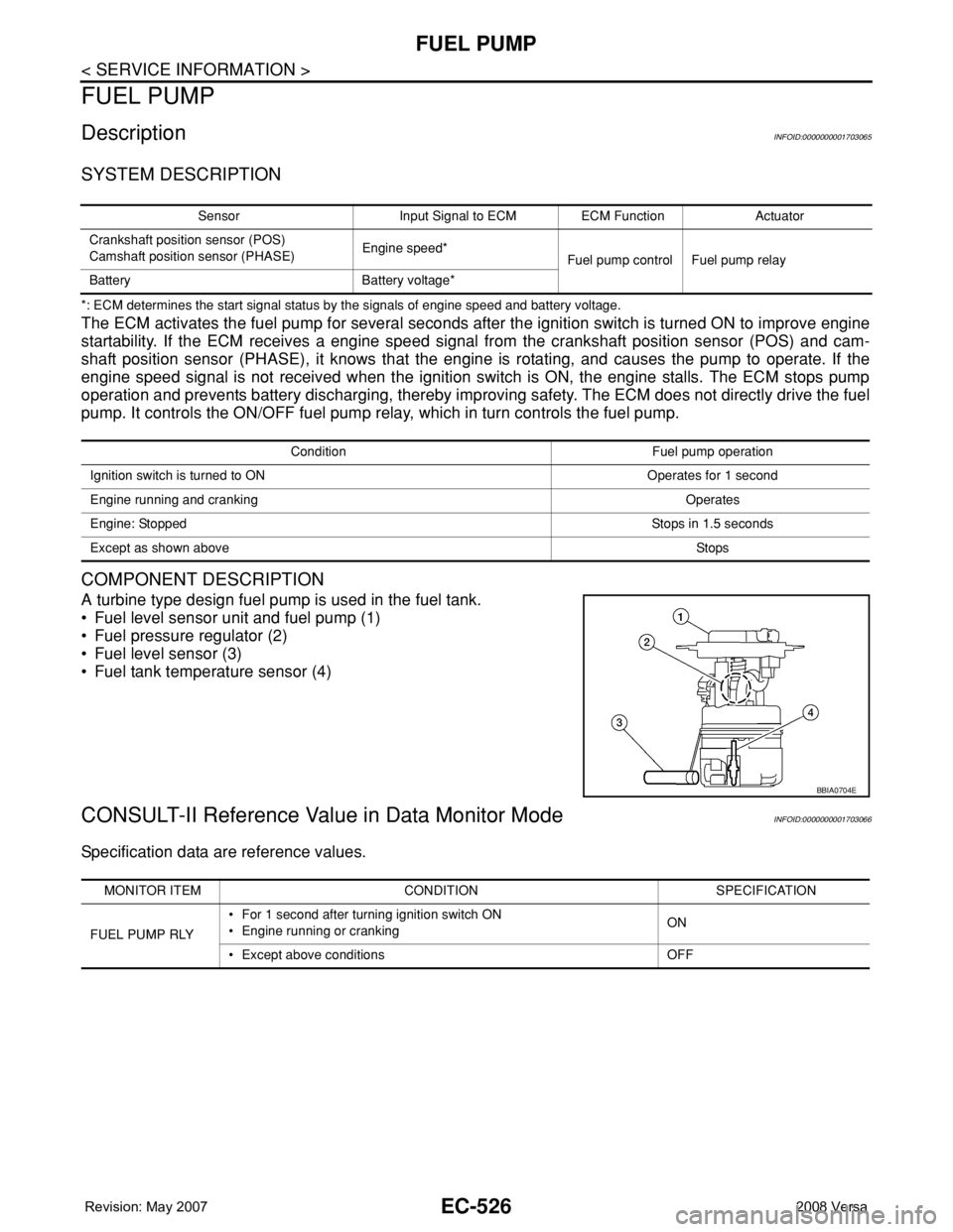
A turbine type design fuel pump is used in the fuel tank.
• Fuel level sensor unit and fuel pump (1)
• Fuel pressure regulator (2)
• Fuel level sensor (3)
• Fuel tank temperature sensor (4)
CONSULT-II Reference Value in Data Monitor ModeINFOID:0000000001703066
Specification data are reference values.
Sensor Input Signal to ECM ECM Function Actuator
Crankshaft position sensor (POS)
Camshaft position sensor (PHASE)Engine speed*
Fuel pump control Fuel pump relay
Battery Battery voltage*
Condition Fuel pump operation
Ignition switch is turned to ON Operates for 1 second
Engine running and crankingOperates
Engine: StoppedStops in 1.5 seconds
Except as shown aboveSt ops
BBIA0704E
MONITOR ITEM CONDITION SPECIFICATION
FUEL PUMP RLY• For 1 second after turning ignition switch ON
• Engine running or crankingON
• Except above conditions OFF
Page 1601 of 2771
FUEL PUMP
EC-527
< SERVICE INFORMATION >
C
D
E
F
G
H
I
J
K
L
MA
EC
N
P O
Wiring DiagramINFOID:0000000001703067
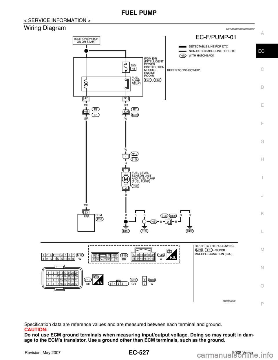
Specification data are reference values and are measured between each terminal and ground.
CAUTION:
Do not use ECM ground terminals when measuring input/output voltage. Doing so may result in dam-
age to the ECM's transistor. Use a ground other than ECM terminals, such as the ground.
BBWA3004E
Page 1602 of 2771
EC-528
< SERVICE INFORMATION >
FUEL PUMP
Diagnosis Procedure
INFOID:0000000001703068
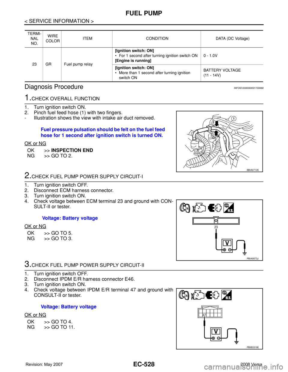
1.CHECK OVERALL FUNCTION
1. Turn ignition switch ON.
2. Pinch fuel feed hose (1) with two fingers.
- Illustration shows the view with intake air duct removed.
OK or NG
OK >>INSPECTION END
NG >> GO TO 2.
2.CHECK FUEL PUMP POWER SUPPLY CIRCUIT-I
1. Turn ignition switch OFF.
2. Disconnect ECM harness connector.
3. Turn ignition switch ON.
4. Check voltage between ECM terminal 23 and ground with CON-
SULT-II or tester.
OK or NG
OK >> GO TO 5.
NG >> GO TO 3.
3.CHECK FUEL PUMP POWER SUPPLY CIRCUIT-II
1. Turn ignition switch OFF.
2. Disconnect IPDM E/R harness connector E46.
3. Turn ignition switch ON.
4. Check voltage between IPDM E/R terminal 47 and ground with
CONSULT-II or tester.
OK or NG
OK >> GO TO 4.
NG >> GO TO 11.
TERMI-
NAL
NO.WIRE
COLORITEM CONDITION DATA (DC Voltage)
23 GR Fuel pump relay[Ignition switch: ON]
• For 1 second after turning ignition switch ON
[Engine is running]0 - 1.0V
[Ignition switch: ON]
• More than 1 second after turning ignition
switch ONBATTERY VOLTAGE
(11 - 14V)
Fuel pressure pulsation should be felt on the fuel feed
hose for 1 second after ignition switch is turned ON.
BBIA0712E
Voltage: Battery voltage
PBIA9573J
Voltage: Battery voltage
PBIB3319E
Page 1603 of 2771
FUEL PUMP
EC-529
< SERVICE INFORMATION >
C
D
E
F
G
H
I
J
K
L
MA
EC
N
P O
4.DETECT MALFUNCTIONING PART
Check the following.
• Harness connectors E8, F8
• Harness for open or short between IPDM E/R and ECM
>> Repair open circuit or short to ground or short to power in harness or connectors.
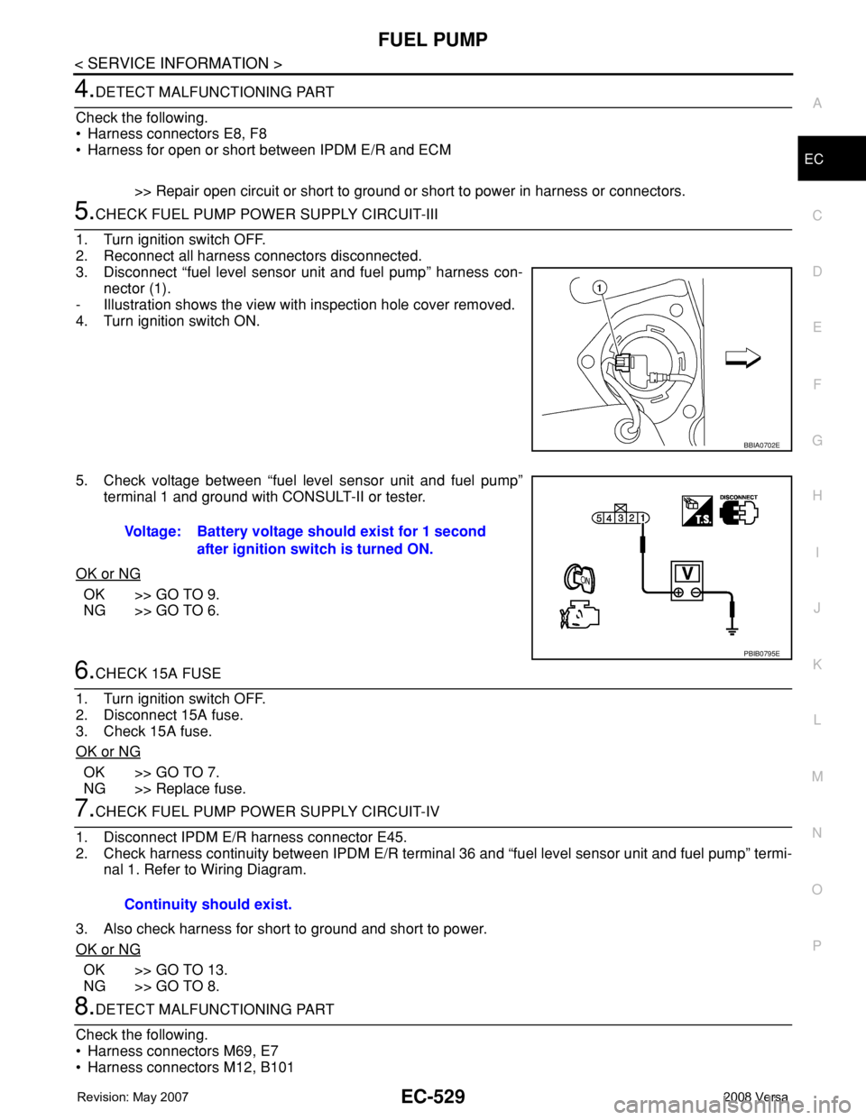
5.CHECK FUEL PUMP POWER SUPPLY CIRCUIT-III
1. Turn ignition switch OFF.
2. Reconnect all harness connectors disconnected.
3. Disconnect “fuel level sensor unit and fuel pump” harness con-
nector (1).
- Illustration shows the view with inspection hole cover removed.
4. Turn ignition switch ON.
5. Check voltage between “fuel level sensor unit and fuel pump”
terminal 1 and ground with CONSULT-II or tester.
OK or NG
OK >> GO TO 9.
NG >> GO TO 6.
6.CHECK 15A FUSE
1. Turn ignition switch OFF.
2. Disconnect 15A fuse.
3. Check 15A fuse.
OK or NG
OK >> GO TO 7.
NG >> Replace fuse.
7.CHECK FUEL PUMP POWER SUPPLY CIRCUIT-IV
1. Disconnect IPDM E/R harness connector E45.
2. Check harness continuity between IPDM E/R terminal 36 and “fuel level sensor unit and fuel pump” termi-
nal 1. Refer to Wiring Diagram.
3. Also check harness for short to ground and short to power.
OK or NG
OK >> GO TO 13.
NG >> GO TO 8.
8.DETECT MALFUNCTIONING PART
Check the following.
• Harness connectors M69, E7
• Harness connectors M12, B101
BBIA0702E
Voltage: Battery voltage should exist for 1 second
after ignition switch is turned ON.
PBIB0795E
Continuity should exist.
Page 1604 of 2771

EC-530
< SERVICE INFORMATION >
FUEL PUMP
• Harness for open or short between IPDM E/R and “fuel level sensor unit and fuel pump”
>> Repair open circuit or short to ground or short to power in harness or connectors.
9.CHECK FUEL PUMP GROUND CIRCUIT
1. Check harness continuity between “fuel level sensor unit and fuel pump” terminal 3 and ground.
Refer to Wiring Diagram.
2. Also check harness for short to power.
OK or NG
OK >> GO TO 10.
NG >> Repair or replace harness or connectors.
10.CHECK FUEL PUMP
Refer to EC-530, "
Component Inspection".
OK or NG
OK >> GO TO 11.
NG >> Replace fuel pump.
11 .CHECK INTERMITTENT INCIDENT
Refer to EC-136
.
OK or NG
OK >> Replace IPDM E/R. Refer to PG-26, "Removal and Installation of IPDM E/R".
NG >> Repair or replace harness or connectors.
Component InspectionINFOID:0000000001703069
FUEL PUMP
1. Disconnect “fuel level sensor unit and fuel pump” harness connector.
2. Check resistance between “fuel level sensor unit and fuel pump”
terminals 1 and 3.
3. If NG, replace “fuel level sensor unit and fuel pump”.
Removal and InstallationINFOID:0000000001703070
FUEL PUMP
Refer to FL-5. Continuity should exist.
Resistance: Approximately 0.2 - 5.0Ω [at 25°C (77°F)]
SEC918C
Page 1613 of 2771
IGNITION SIGNAL
EC-539
< SERVICE INFORMATION >
C
D
E
F
G
H
I
J
K
L
MA
EC
N
P O
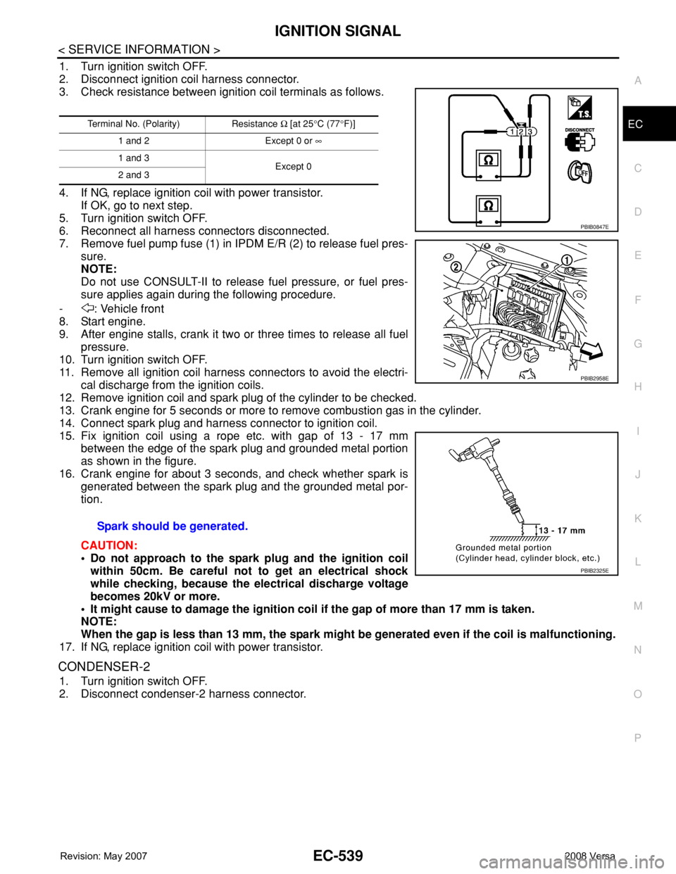
1. Turn ignition switch OFF.
2. Disconnect ignition coil harness connector.
3. Check resistance between ignition coil terminals as follows.
4. If NG, replace ignition coil with power transistor.
If OK, go to next step.
5. Turn ignition switch OFF.
6. Reconnect all harness connectors disconnected.
7. Remove fuel pump fuse (1) in IPDM E/R (2) to release fuel pres-
sure.
NOTE:
Do not use CONSULT-II to release fuel pressure, or fuel pres-
sure applies again during the following procedure.
- : Vehicle front
8. Start engine.
9. After engine stalls, crank it two or three times to release all fuel
pressure.
10. Turn ignition switch OFF.
11. Remove all ignition coil harness connectors to avoid the electri-
cal discharge from the ignition coils.
12. Remove ignition coil and spark plug of the cylinder to be checked.
13. Crank engine for 5 seconds or more to remove combustion gas in the cylinder.
14. Connect spark plug and harness connector to ignition coil.
15. Fix ignition coil using a rope etc. with gap of 13 - 17 mm
between the edge of the spark plug and grounded metal portion
as shown in the figure.
16. Crank engine for about 3 seconds, and check whether spark is
generated between the spark plug and the grounded metal por-
tion.
CAUTION:
• Do not approach to the spark plug and the ignition coil
within 50cm. Be careful not to get an electrical shock
while checking, because the electrical discharge voltage
becomes 20kV or more.
• It might cause to damage the ignition coil if the gap of more than 17 mm is taken.
NOTE:
When the gap is less than 13 mm, the spark might be generated even if the coil is malfunctioning.
17. If NG, replace ignition coil with power transistor.
CONDENSER-2
1. Turn ignition switch OFF.
2. Disconnect condenser-2 harness connector.
Terminal No. (Polarity) Resistance Ω [at 25°C (77°F)]
1 and 2 Except 0 or ∞
1 and 3
Except 0
2 and 3
Spark should be generated.
PBIB0847E
PBIB2958E
PBIB2325E