Page 1929 of 2771

GW-28
< SERVICE INFORMATION >
POWER WINDOW SYSTEM
Terminal and Reference Value for BCM
INFOID:0000000001704145
Refer to BCS-11, "Terminal and Reference Value for BCM" .
Work FlowINFOID:0000000001704146
1. Check the symptom and customer's requests.
2. Understand the outline of system. Refer to GW-18, "
System Description" .
3. According to the trouble diagnosis chart, repair or replace the cause of the malfunction.
Refer to GW-29, "
Trouble Diagnosis Symptom Chart" .
4. Does power window system operate normally? If Yes, GO TO 5, If No, GO TO 3.
5. Inspection End.
CONSULT-III Function (BCM)INFOID:0000000001704147
CONSULT-III can display each diagnostic item using the diagnostic test modes shown following.
ACTIVE TEST
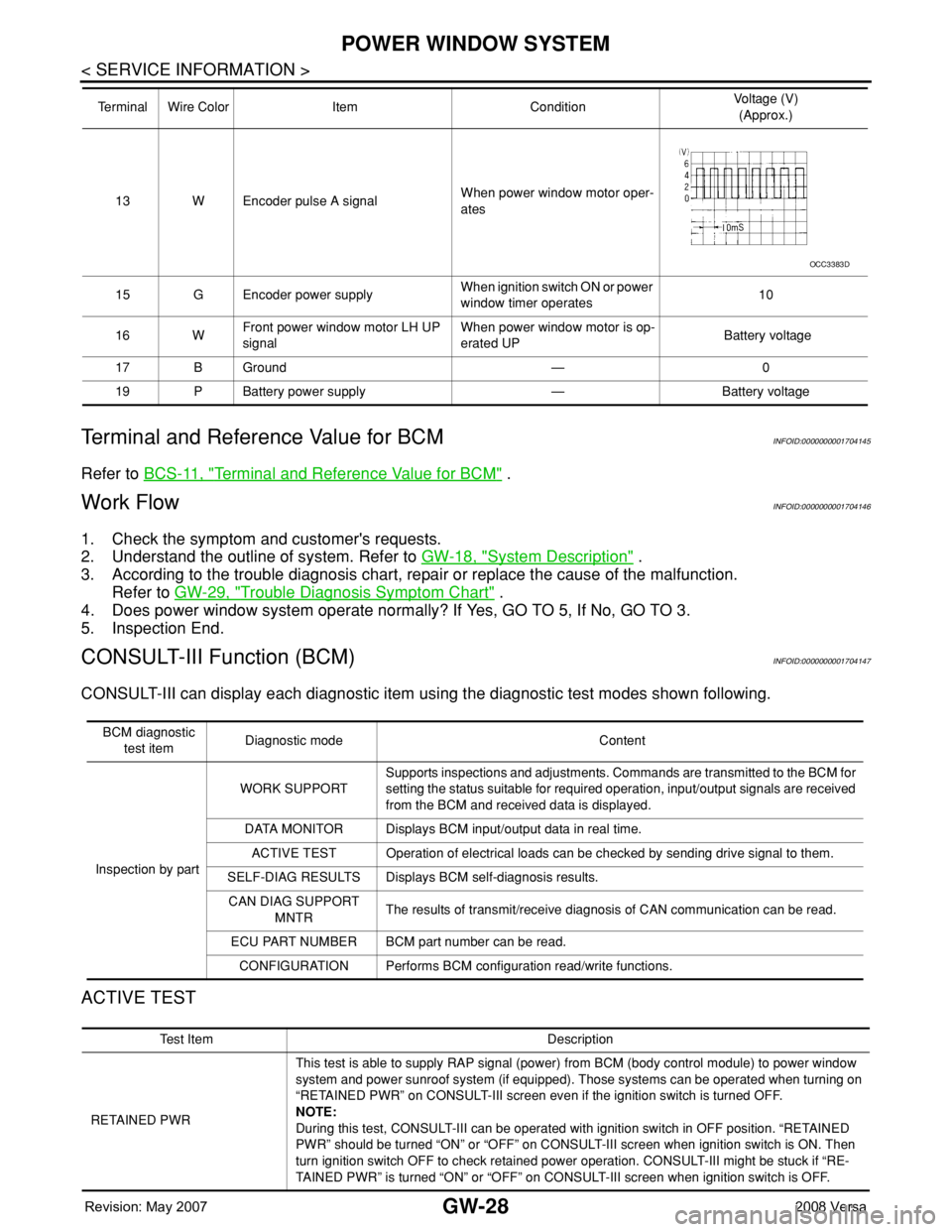
13 W Encoder pulse A signalWhen power window motor oper-
ates
15 G Encoder power supplyWhen ignition switch ON or power
window timer operates10
16 WFront power window motor LH UP
signalWhen power window motor is op-
erated UP Battery voltage
17 B Ground — 0
19 P Battery power supply — Battery voltage Terminal Wire Color Item ConditionVoltage (V)
(Approx.)
OCC3383D
BCM diagnostic
test itemDiagnostic mode Content
Inspection by partWORK SUPPORTSupports inspections and adjustments. Commands are transmitted to the BCM for
setting the status suitable for required operation, input/output signals are received
from the BCM and received data is displayed.
DATA MONITOR Displays BCM input/output data in real time.
ACTIVE TEST Operation of electrical loads can be checked by sending drive signal to them.
SELF-DIAG RESULTS Displays BCM self-diagnosis results.
CAN DIAG SUPPORT
MNTRThe results of transmit/receive diagnosis of CAN communication can be read.
ECU PART NUMBER BCM part number can be read.
CONFIGURATION Performs BCM configuration read/write functions.
Te s t I t e m D e s c r i p t i o n
RETAINED PWRThis test is able to supply RAP signal (power) from BCM (body control module) to power window
system and power sunroof system (if equipped). Those systems can be operated when turning on
“RETAINED PWR” on CONSULT-III screen even if the ignition switch is turned OFF.
NOTE:
During this test, CONSULT-III can be operated with ignition switch in OFF position. “RETAINED
PWR” should be turned “ON” or “OFF” on CONSULT-III screen when ignition switch is ON. Then
turn ignition switch OFF to check retained power operation. CONSULT-III might be stuck if “RE-
TAINED PWR” is turned “ON” or “OFF” on CONSULT-III screen when ignition switch is OFF.
Page 1943 of 2771
GW-42
< SERVICE INFORMATION >
FRONT DOOR GLASS AND REGULATOR
FRONT DOOR GLASS AND REGULATOR
Removal and InstallationINFOID:0000000001704160
DOOR GLASS
Removal
1. Remove the front door finisher. Refer to EI-32, "Removal and Installation".
2. Disconnect the front door speaker electrical connector.
3. Position aside the sealing screen.
NOTE:
If sealing the screen is reused, cut the butyl-tape so that a part of butyl-tape remains on the sealing
screen.
4. If equipped, reconnect the power window switch electrical con-
nector. Operate the power window main switch to raise/lower
the door window until the glass bolts can be seen.
5. Remove the door glass bolts.
1. Door panel 2. Lower sash (front) 3. Lower sash (rear)
4. Door glass run 5. Door glass 6. Regulator assembly
7. Power window motor (if equipped)
PIIB2631J
PIIB2632J
Page 1945 of 2771

GW-44
< SERVICE INFORMATION >
FRONT DOOR GLASS AND REGULATOR
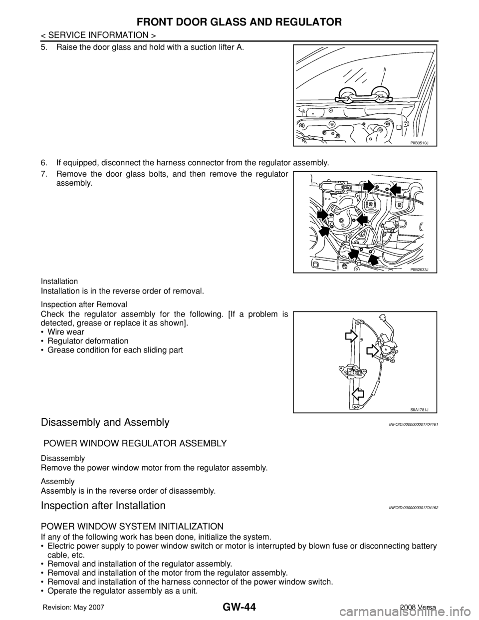
5. Raise the door glass and hold with a suction lifter A.
6. If equipped, disconnect the harness connector from the regulator assembly.
7. Remove the door glass bolts, and then remove the regulator
assembly.
Installation
Installation is in the reverse order of removal.
Inspection after Removal
Check the regulator assembly for the following. [If a problem is
detected, grease or replace it as shown].
• Wire wear
• Regulator deformation
• Grease condition for each sliding part
Disassembly and AssemblyINFOID:0000000001704161
POWER WINDOW REGULATOR ASSEMBLY
Disassembly
Remove the power window motor from the regulator assembly.
Assembly
Assembly is in the reverse order of disassembly.
Inspection after InstallationINFOID:0000000001704162
POWER WINDOW SYSTEM INITIALIZATION
If any of the following work has been done, initialize the system.
• Electric power supply to power window switch or motor is interrupted by blown fuse or disconnecting battery
cable, etc.
• Removal and installation of the regulator assembly.
• Removal and installation of the motor from the regulator assembly.
• Removal and installation of the harness connector of the power window switch.
• Operate the regulator assembly as a unit.
PIIB3510J
PIIB2633J
SIIA1781J
Page 2491 of 2771

PG-58
< SERVICE INFORMATION >
HARNESS
Wiring Diagram Codes (Cell Codes)
INFOID:0000000001704709
Use the chart below to find out what each wiring diagram code stands for.
Refer to the wiring diagram code in the alphabetical index to find the location (page number) of each wiring
diagram.
D3 D404 W/3 : Rear wiper motor
D4 D405 W/4 : Back door lock assembly
D4 D406 W/2 : Back door request switch
E2 D407 W/2 : High mounted stop lamp
D4 D408 BR/2 : Back door opener switch
E4 D409 B/1 : Condenser-1
C2 D410 — : Body ground
E3 D411 B/1 : Condenser-1
E1 D412 B/1 : Rear window defogger (+)
C2 D413 B/1 : Rear window defogger (-)
F3 D414 — : Body ground
Code Section Wiring Diagram Name
ABS BRC Anti-lock Brake System
A/C,M MTC Manual Air Conditioner
APPS1 EC Accelerator Pedal Position Sensor
A/F EC Air Fuel Ratio Sensor 1
A/FH EC Air Fuel Ratio Sensor 1 Heater
APPS2 EC Accelerator Pedal Position Sensor
APPS3 EC Accelerator Pedal Position Sensor
ASC/BS EC ASCD Brake Switch
ASC/SW EC ASCD Steering Switch
ASCBOF EC ASCD Brake Switch
ASCIND EC ASCD Indicator
AT/IND DI A/T Indicator Lamp
AUDIO AV Audio
BACK/L LT Back-up Lamp
BA/FTS AT A/T Fluid Temperature Sensor and TCM Power Supply
B/DOOR BL Back Door Opener
BRK/SW EC Brake Switch
CAN AT CAN Communication Line
CAN CVT CAN Communication Line
CAN EC CAN Communication Line
CAN LAN CAN System
CHARGE SC Charging System
CHIME DI Warning Chime
COOL/F EC Cooling Fan Control
COMBSW LT Combination Switch
CVTIND DI CVT Indicator Lamp
D/LOCK BL Power Door Lock
DEF GW Rear Window Defogger
DTRL LT Headlamp - With Daytime Light System
ECTS EC Engine Coolant Temperature Sensor
ENGSS AT Engine Speed Signal
EPS STC Electronic Controlled Power Steering
ETC1 EC Electric Throttle Control Function