2008 NISSAN TIIDA Transaxle Assembly
[x] Cancel search: Transaxle AssemblyPage 1016 of 2771
DIFFERENTIAL SIDE OIL SEAL
CVT-177
< SERVICE INFORMATION >
D
E
F
G
H
I
J
K
L
MA
B
CVT
N
O
P
DIFFERENTIAL SIDE OIL SEAL
Removal and InstallationINFOID:0000000001703686
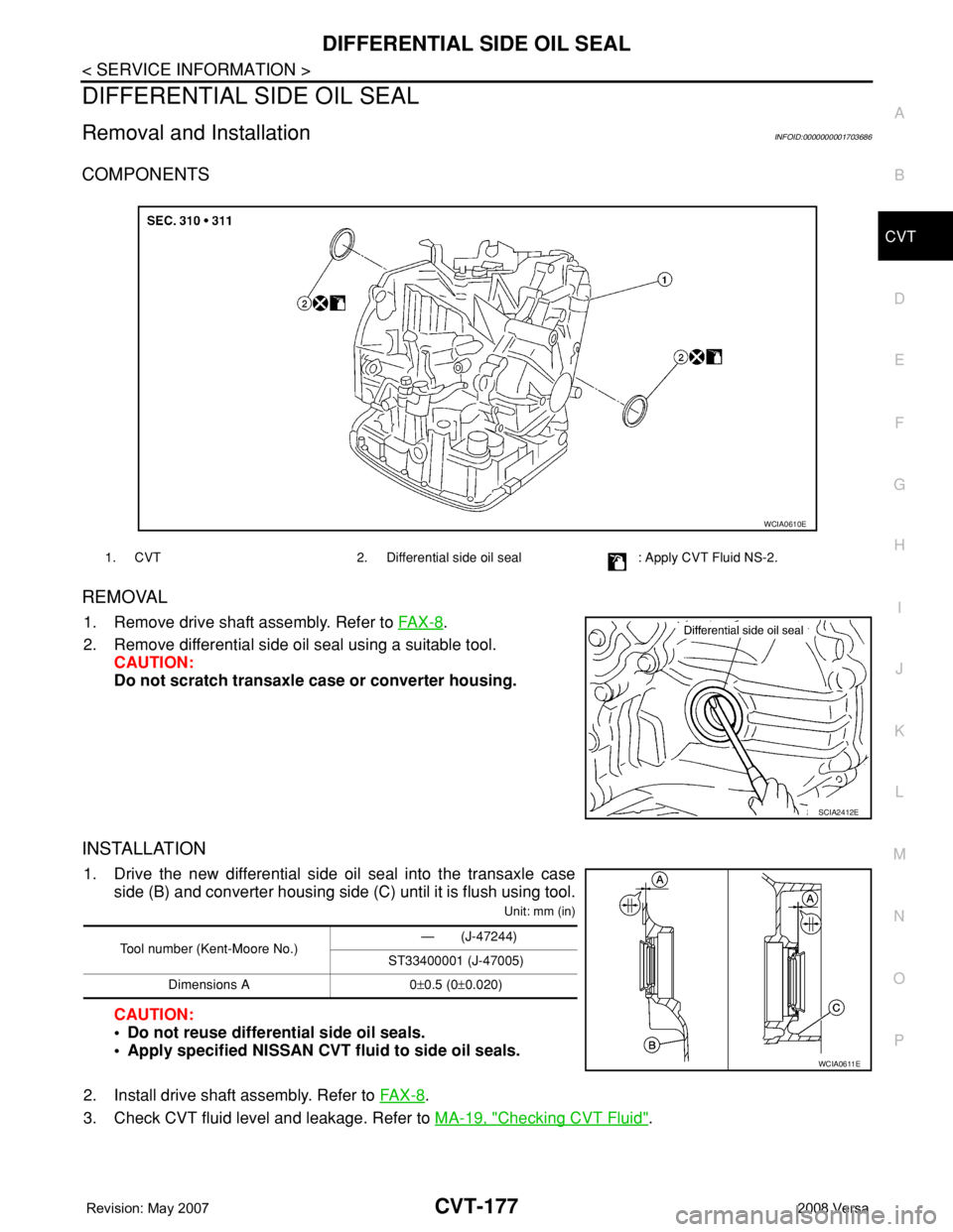
COMPONENTS
REMOVAL
1. Remove drive shaft assembly. Refer to FA X - 8.
2. Remove differential side oil seal using a suitable tool.
CAUTION:
Do not scratch transaxle case or converter housing.
INSTALLATION
1. Drive the new differential side oil seal into the transaxle case
side (B) and converter housing side (C) until it is flush using tool.
Unit: mm (in)
CAUTION:
• Do not reuse differential side oil seals.
• Apply specified NISSAN CVT fluid to side oil seals.
2. Install drive shaft assembly. Refer to FA X - 8
.
3. Check CVT fluid level and leakage. Refer to MA-19, "
Checking CVT Fluid".
1. CVT 2. Differential side oil seal : Apply CVT Fluid NS-2.
WCIA0610E
SCIA2412E
Tool number (Kent-Moore No.)— (J-47244)
ST33400001 (J-47005)
Dimensions A 0±0.5 (0±0.020)
WCIA0611E
Page 1017 of 2771
CVT-178
< SERVICE INFORMATION >
TRANSAXLE ASSEMBLY
TRANSAXLE ASSEMBLY
Removal and InstallationINFOID:0000000001703687
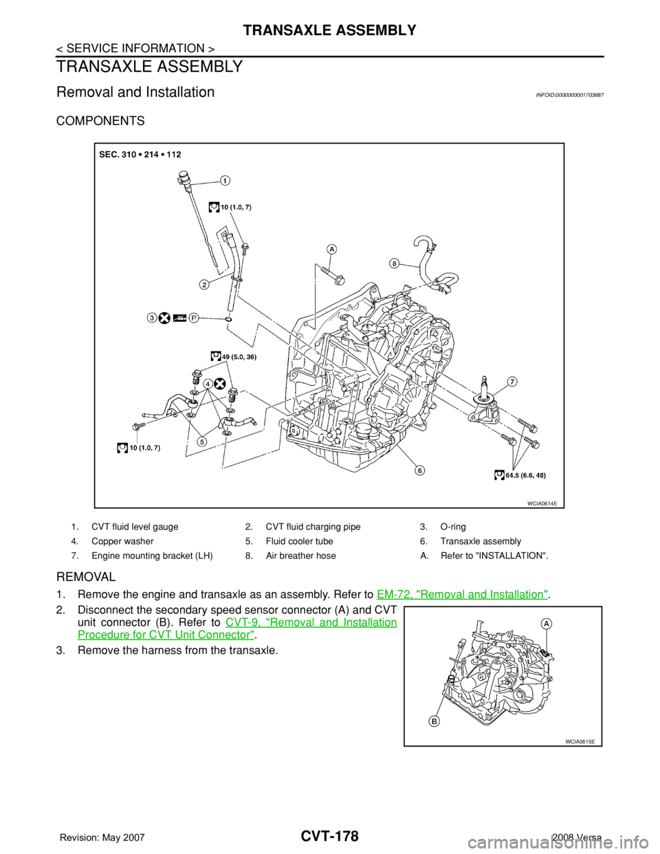
COMPONENTS
REMOVAL
1. Remove the engine and transaxle as an assembly. Refer to EM-72, "Removal and Installation".
2. Disconnect the secondary speed sensor connector (A) and CVT
unit connector (B). Refer to CVT-9, "
Removal and Installation
Procedure for CVT Unit Connector".
3. Remove the harness from the transaxle.
1. CVT fluid level gauge 2. CVT fluid charging pipe 3. O-ring
4. Copper washer 5. Fluid cooler tube 6. Transaxle assembly
7. Engine mounting bracket (LH) 8. Air breather hose A. Refer to "INSTALLATION".
WCIA0614E
WCIA0615E
Page 1018 of 2771
TRANSAXLE ASSEMBLY
CVT-179
< SERVICE INFORMATION >
D
E
F
G
H
I
J
K
L
MA
B
CVT
N
O
P
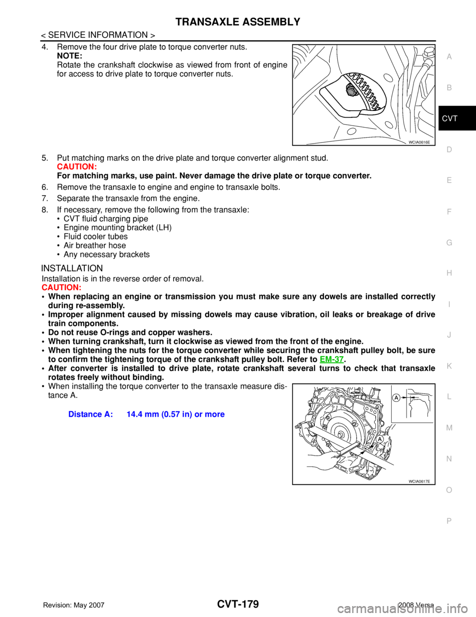
4. Remove the four drive plate to torque converter nuts.
NOTE:
Rotate the crankshaft clockwise as viewed from front of engine
for access to drive plate to torque converter nuts.
5. Put matching marks on the drive plate and torque converter alignment stud.
CAUTION:
For matching marks, use paint. Never damage the drive plate or torque converter.
6. Remove the transaxle to engine and engine to transaxle bolts.
7. Separate the transaxle from the engine.
8. If necessary, remove the following from the transaxle:
• CVT fluid charging pipe
• Engine mounting bracket (LH)
• Fluid cooler tubes
• Air breather hose
• Any necessary brackets
INSTALLATION
Installation is in the reverse order of removal.
CAUTION:
• When replacing an engine or transmission you must make sure any dowels are installed correctly
during re-assembly.
• Improper alignment caused by missing dowels may cause vibration, oil leaks or breakage of drive
train components.
• Do not reuse O-rings and copper washers.
• When turning crankshaft, turn it clockwise as viewed from the front of the engine.
• When tightening the nuts for the torque converter while securing the crankshaft pulley bolt, be sure
to confirm the tightening torque of the crankshaft pulley bolt. Refer to EM-37
.
• After converter is installed to drive plate, rotate crankshaft several turns to check that transaxle
rotates freely without binding.
• When installing the torque converter to the transaxle measure dis-
tance A.
WCIA0616E
Distance A: 14.4 mm (0.57 in) or more
WCIA0617E
Page 1019 of 2771
CVT-180
< SERVICE INFORMATION >
TRANSAXLE ASSEMBLY
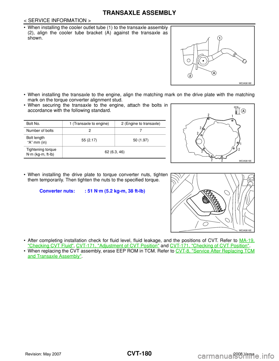
• When installing the cooler outlet tube (1) to the transaxle assembly
(2), align the cooler tube bracket (A) against the transaxle as
shown.
• When installing the transaxle to the engine, align the matching mark on the drive plate with the matching
mark on the torque converter alignment stud.
• When securing the transaxle to the engine, attach the bolts in
accordance with the following standard.
• When installing the drive plate to torque converter nuts, tighten
them temporarily. Then tighten the nuts to the specified torque.
• After completing installation check for fluid level, fluid leakage, and the positions of CVT. Refer to MA-19,
"Checking CVT Fluid", CVT-171, "Adjustment of CVT Position" and CVT-171, "Checking of CVT Position".
• When replacing the CVT assembly, erase EEP ROM in TCM. Refer to CVT-8, "
Service After Replacing TCM
and Transaxle Assembly".
WCIA0618E
Bolt No. 1 (Transaxle to engine) 2 (Engine to transaxle)
Number of bolts 2 7
Bolt length
“A” mm (in)55 (2.17) 50 (1.97)
Tightening torque
N·m (kg-m, ft-lb)62 (6.3, 46)
WCIA0619E
Converter nuts: : 51 N·m (5.2 kg-m, 38 ft-lb)
WCIA0616E
Page 1702 of 2771
OIL PAN
EM-25
< SERVICE INFORMATION >
C
D
E
F
G
H
I
J
K
L
MA
EM
N
P O
1. Drain engine oil. Refer to LU-6.
2. Remove engine and transaxle assembly. Refer to EM-72
.
3. Remove oil filter using Tool.
CAUTION:
When removing, prepare a shop cloth to absorb any engine oil leakage or spillage.
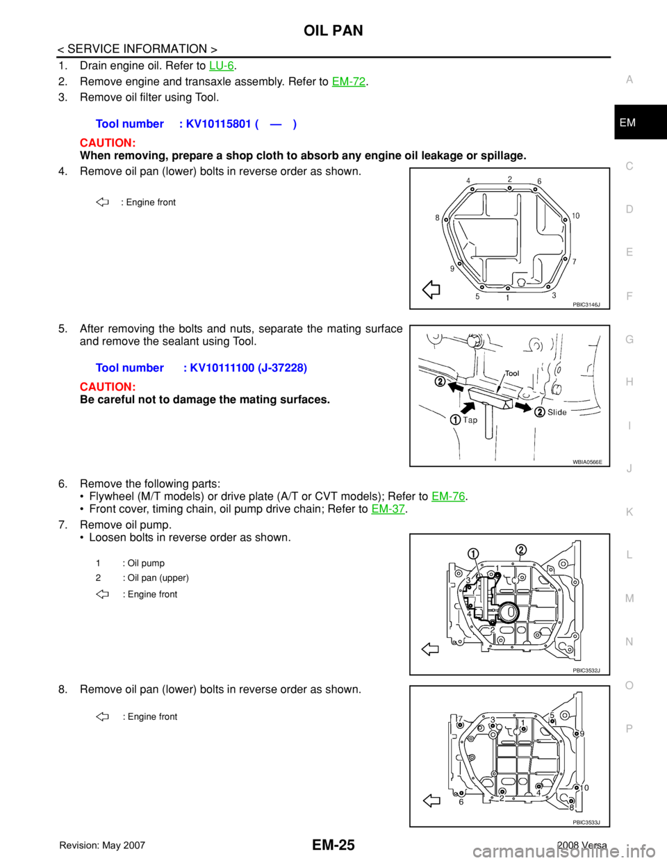
4. Remove oil pan (lower) bolts in reverse order as shown.
5. After removing the bolts and nuts, separate the mating surface
and remove the sealant using Tool.
CAUTION:
Be careful not to damage the mating surfaces.
6. Remove the following parts:
• Flywheel (M/T models) or drive plate (A/T or CVT models); Refer to EM-76
.
• Front cover, timing chain, oil pump drive chain; Refer to EM-37
.
7. Remove oil pump.
• Loosen bolts in reverse order as shown.
8. Remove oil pan (lower) bolts in reverse order as shown.Tool number : KV10115801 ( — )
: Engine front
PBIC3146J
Tool number : KV10111100 (J-37228)
WBIA0566E
1: Oil pump
2 : Oil pan (upper)
: Engine front
PBIC3532J
: Engine front
PBIC3533J
Page 1737 of 2771
EM-60
< SERVICE INFORMATION >
OIL SEAL
• Drive belt; Refer to EM-13, "Component".
• Crankshaft pulley; Refer to EM-37, "
Component".
2. Remove front oil seal using a suitable tool.
CAUTION:
Be careful not to damage front cover and crankshaft.
INSTALLATION
1. Apply new engine oil to new front oil seal joint surface and seal lip.
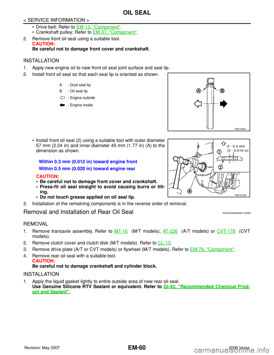
2. Install front oil seal so that each seal lip is oriented as shown.
• Install front oil seal (2) using a suitable tool with outer diameter
57 mm (2.24 in) and inner diameter 45 mm (1.77 in) (A) to the
dimension as shown.
CAUTION:
• Be careful not to damage front cover and crankshaft.
• Press-fit oil seal straight to avoid causing burrs or tilt-
ing.
• Do not touch grease applied on oil seal lip.
3. Installation of the remaining components is in the reverse order of removal.
Removal and Installation of Rear Oil SealINFOID:0000000001702500
REMOVAL
1. Remove transaxle assembly. Refer to MT-16 (M/T models), AT-226 (A/T models) or CVT-178 (CVT
models).
2. Remove clutch cover and clutch disk (M/T models). Refer to CL-13
.
3. Remove drive plate (A/T or CVT models) or flywheel (M/T models). Refer to EM-76, "
Component".
4. Remove rear oil seal with a suitable tool.
CAUTION:
Be careful not to damage crankshaft and cylinder block.
INSTALLATION
1. Apply the liquid gasket lightly to entire outside area of new rear oil seal.
Use Genuine Silicone RTV Sealant or equivalent. Refer to GI-42, "
Recommended Chemical Prod-
uct and Sealant".
A : Dust seal lip
B : Oil seal lip
: Engine outside
: Engine inside
PBIC3485J
Within 0.3 mm (0.012 in) toward engine front
Within 0.5 mm (0.020 in) toward engine rear
PBIC3729E
Page 1750 of 2771
ENGINE ASSEMBLY
EM-73
< SERVICE INFORMATION >
C
D
E
F
G
H
I
J
K
L
MA
EM
N
P O
• Use either 2-pole lift type or separate type lift as best you can. If board-on type is used for unavoid-
able reasons, support at the rear axle jacking point with a transmission jack or similar tool before
starting work, in preparation for the backward shift of center of gravity.
• For supporting points for lifting and jacking point at rear axle, refer to GI-38, "
Garage Jack and
Safety Stand and 2-Pole Lift".
REMOVAL
Remove the engine and the transaxle assembly from the vehicle downward. Separate the engine and the tran-
saxle.
1. Remove engine undercover
2. Drain engine coolant from radiator. Refer to CO-8, "
Changing Engine Coolant".
CAUTION:
• Perform this step when the engine is cold.
• Do not spill engine coolant on drive belt.
3. Remove front fender protector (RH and LH); Refer to EI-23
.
4. Remove exhaust front tube; Refer to EX-4
.
5. Remove drive shafts (LH and RH) from steering knuckle. Refer to FAX-8
.
6. Remove transaxle joint bolts which pierce at oil pan (upper) lower rear side. Refer to AT-226
(A/T models),
CVT-178
(CVT) or MT-16 (M/T models).
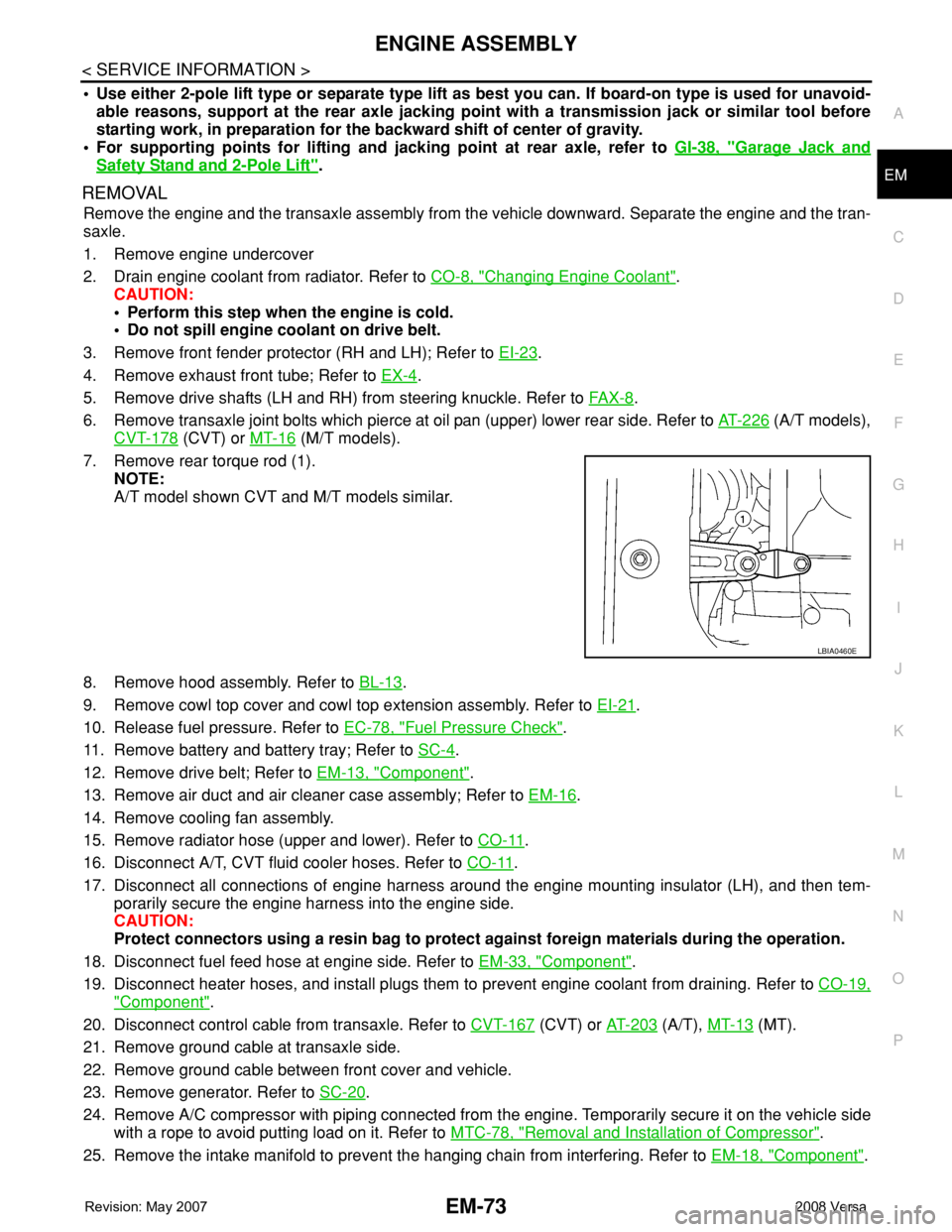
7. Remove rear torque rod (1).
NOTE:
A/T model shown CVT and M/T models similar.
8. Remove hood assembly. Refer to BL-13
.
9. Remove cowl top cover and cowl top extension assembly. Refer to EI-21
.
10. Release fuel pressure. Refer to EC-78, "
Fuel Pressure Check".
11. Remove battery and battery tray; Refer to SC-4
.
12. Remove drive belt; Refer to EM-13, "
Component".
13. Remove air duct and air cleaner case assembly; Refer to EM-16
.
14. Remove cooling fan assembly.
15. Remove radiator hose (upper and lower). Refer to CO-11
.
16. Disconnect A/T, CVT fluid cooler hoses. Refer to CO-11
.
17. Disconnect all connections of engine harness around the engine mounting insulator (LH), and then tem-
porarily secure the engine harness into the engine side.
CAUTION:
Protect connectors using a resin bag to protect against foreign materials during the operation.
18. Disconnect fuel feed hose at engine side. Refer to EM-33, "
Component".
19. Disconnect heater hoses, and install plugs them to prevent engine coolant from draining. Refer to CO-19,
"Component".
20. Disconnect control cable from transaxle. Refer to CVT-167
(CVT) or AT-203 (A/T), MT-13 (MT).
21. Remove ground cable at transaxle side.
22. Remove ground cable between front cover and vehicle.
23. Remove generator. Refer to SC-20
.
24. Remove A/C compressor with piping connected from the engine. Temporarily secure it on the vehicle side
with a rope to avoid putting load on it. Refer to MTC-78, "
Removal and Installation of Compressor".
25. Remove the intake manifold to prevent the hanging chain from interfering. Refer to EM-18, "
Component".
LBIA0460E
Page 1751 of 2771
EM-74
< SERVICE INFORMATION >
ENGINE ASSEMBLY
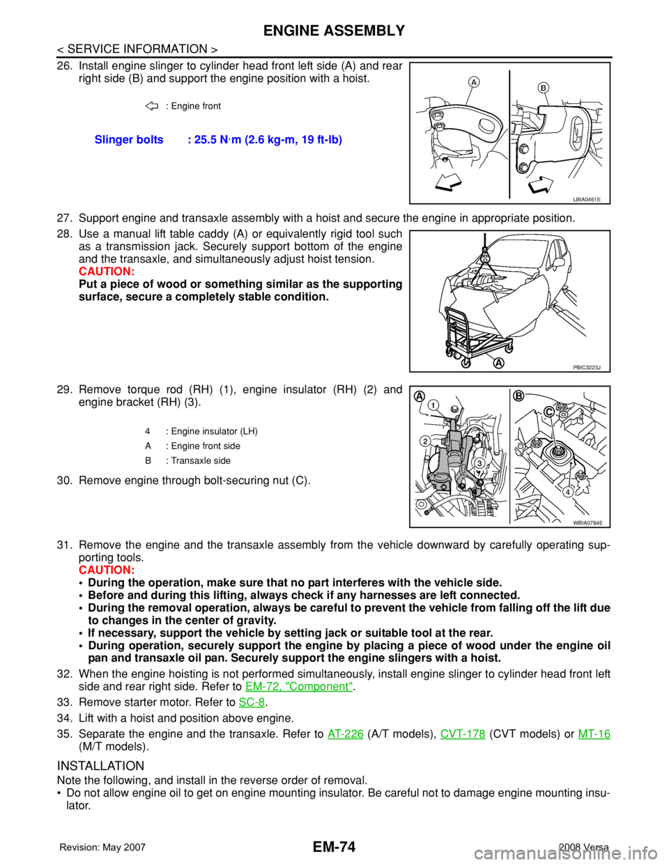
26. Install engine slinger to cylinder head front left side (A) and rear
right side (B) and support the engine position with a hoist.
27. Support engine and transaxle assembly with a hoist and secure the engine in appropriate position.
28. Use a manual lift table caddy (A) or equivalently rigid tool such
as a transmission jack. Securely support bottom of the engine
and the transaxle, and simultaneously adjust hoist tension.
CAUTION:
Put a piece of wood or something similar as the supporting
surface, secure a completely stable condition.
29. Remove torque rod (RH) (1), engine insulator (RH) (2) and
engine bracket (RH) (3).
30. Remove engine through bolt-securing nut (C).
31. Remove the engine and the transaxle assembly from the vehicle downward by carefully operating sup-
porting tools.
CAUTION:
• During the operation, make sure that no part interferes with the vehicle side.
• Before and during this lifting, always check if any harnesses are left connected.
• During the removal operation, always be careful to prevent the vehicle from falling off the lift due
to changes in the center of gravity.
• If necessary, support the vehicle by setting jack or suitable tool at the rear.
• During operation, securely support the engine by placing a piece of wood under the engine oil
pan and transaxle oil pan. Securely support the engine slingers with a hoist.
32. When the engine hoisting is not performed simultaneously, install engine slinger to cylinder head front left
side and rear right side. Refer to EM-72, "
Component".
33. Remove starter motor. Refer to SC-8
.
34. Lift with a hoist and position above engine.
35. Separate the engine and the transaxle. Refer to AT-226
(A/T models), CVT-178 (CVT models) or MT-16
(M/T models).
INSTALLATION
Note the following, and install in the reverse order of removal.
• Do not allow engine oil to get on engine mounting insulator. Be careful not to damage engine mounting insu-
lator.
: Engine front
Slinger bolts : 25.5 N·m (2.6 kg-m, 19 ft-lb)
LBIA0461E
PBIC3223J
4 : Engine insulator (LH)
A : Engine front side
B : Transaxle side
WBIA0784E