Page 937 of 2771

CVT-98
< SERVICE INFORMATION >
DTC P0745 LINE PRESSURE SOLENOID VALVE
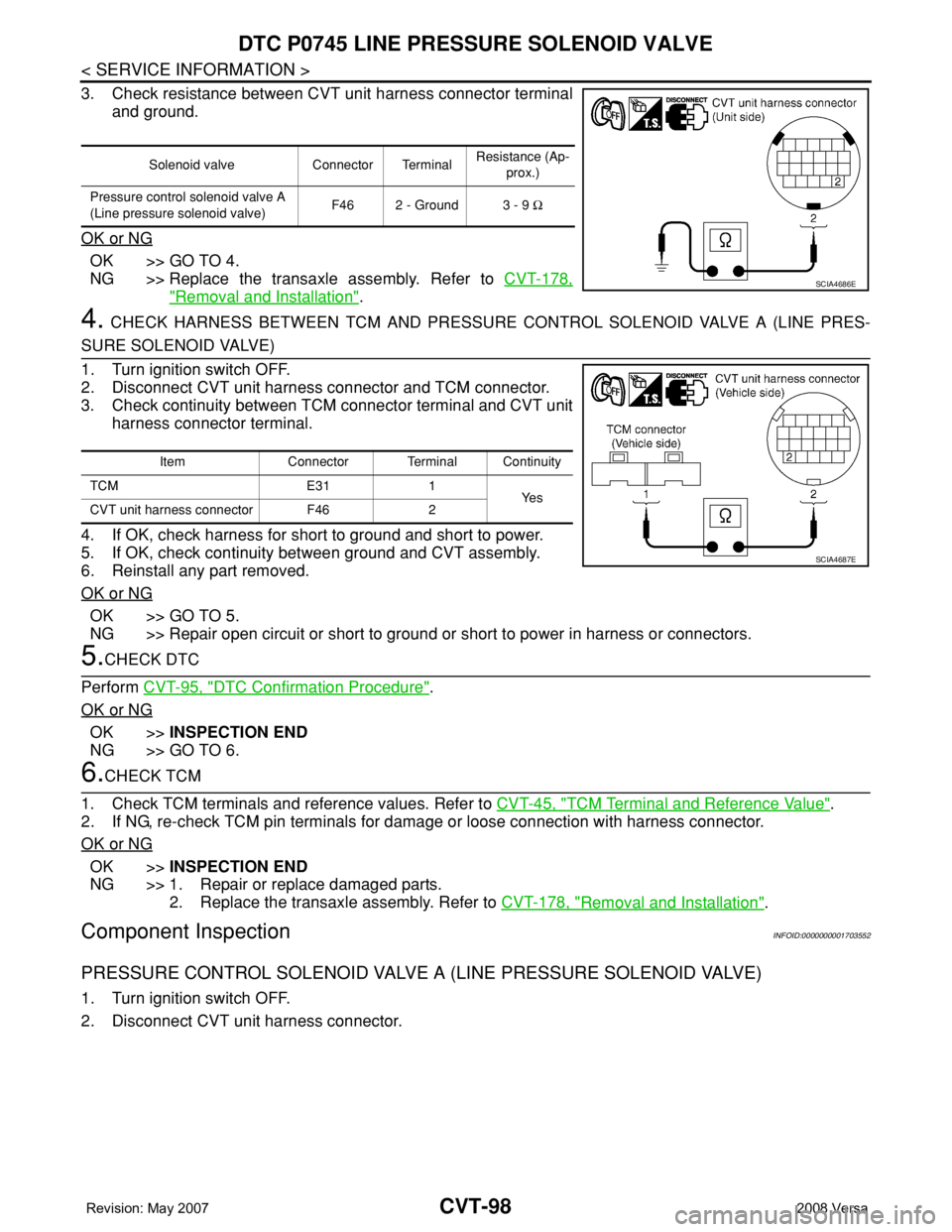
3. Check resistance between CVT unit harness connector terminal
and ground.
OK or NG
OK >> GO TO 4.
NG >> Replace the transaxle assembly. Refer to CVT-178,
"Removal and Installation".
4. CHECK HARNESS BETWEEN TCM AND PRESSURE CONTROL SOLENOID VALVE A (LINE PRES-
SURE SOLENOID VALVE)
1. Turn ignition switch OFF.
2. Disconnect CVT unit harness connector and TCM connector.
3. Check continuity between TCM connector terminal and CVT unit
harness connector terminal.
4. If OK, check harness for short to ground and short to power.
5. If OK, check continuity between ground and CVT assembly.
6. Reinstall any part removed.
OK or NG
OK >> GO TO 5.
NG >> Repair open circuit or short to ground or short to power in harness or connectors.
5.CHECK DTC
Perform CVT-95, "
DTC Confirmation Procedure".
OK or NG
OK >>INSPECTION END
NG >> GO TO 6.
6.CHECK TCM
1. Check TCM terminals and reference values. Refer to CVT-45, "
TCM Terminal and Reference Value".
2. If NG, re-check TCM pin terminals for damage or loose connection with harness connector.
OK or NG
OK >>INSPECTION END
NG >> 1. Repair or replace damaged parts.
2. Replace the transaxle assembly. Refer to CVT-178, "
Removal and Installation".
Component InspectionINFOID:0000000001703552
PRESSURE CONTROL SOLENOID VALVE A (LINE PRESSURE SOLENOID VALVE)
1. Turn ignition switch OFF.
2. Disconnect CVT unit harness connector.
Solenoid valve Connector TerminalResistance (Ap-
prox.)
Pressure control solenoid valve A
(Line pressure solenoid valve) F46 2 - Ground 3 - 9 Ω
SCIA4686E
Item Connector Terminal Continuity
TCM E31 1
Ye s
CVT unit harness connector F46 2
SCIA4687E
Page 938 of 2771
DTC P0745 LINE PRESSURE SOLENOID VALVE
CVT-99
< SERVICE INFORMATION >
D
E
F
G
H
I
J
K
L
MA
B
CVT
N
O
P
3. Check resistance between CVT unit harness connector terminal
and ground.
4. If NG, replace the transaxle assembly. Refer to CVT-178,
"Removal and Installation".
Solenoid valve Connector TerminalResistance (Ap-
prox.)
Pressure control solenoid valve A
(Line pressure solenoid valve) F46 2 - Ground 3 - 9 Ω
SCIA4686E
Page 940 of 2771

DTC P0746 PRESSURE CONTROL SOLENOID A PERFORMANCE (LINE PRES-
SURE SOLENOID VALVE)
CVT-101
< SERVICE INFORMATION >
D
E
F
G
H
I
J
K
L
MA
B
CVT
N
O
P
Without CONSULT-III
1. Start engine.
2. Check voltage between TCM connector terminal and ground.
OK or NG
OK >> GO TO 5.
NG >> GO TO 2.
2.CHECK LINE PRESSURE
Perform line pressure test. Refer to CVT-36, "
Inspections before Trouble Diagnosis".
OK or NG
OK >> GO TO 3.
NG >> Repair or replace damaged parts. Refer to CVT-36, "
Inspections before Trouble Diagnosis".
3.DETECT MALFUNCTIONING ITEM
Check pressure control solenoid valve A (line pressure solenoid valve). Refer to CVT-98, "
Component Inspec-
tion".
OK or NG
OK >> GO TO 4.
NG >> Repair or replace damaged parts.
4.CHECK OUTPUT SPEED SENSOR (SECONDARY SPEED SENSOR) SYSTEM AND INPUT SPEED
SENSOR (PRIMARY SPEED SENSOR) SYSTEM
Check output speed sensor (secondary speed sensor) system and input speed sensor (primary speed sensor)
system. Refer to CVT-80
, CVT-76.
OK or NG
OK >> GO TO 5.
NG >> Repair or replace damaged parts.
5.DETECT MALFUNCTIONING ITEM
Check the following:
• Power supply and ground circuit for TCM. Refer to CVT-122, "
Wiring Diagram - CVT - POWER".
• The TCM pin terminals for damage or loose connection with harness connector.
OK or NG
OK >> GO TO 6.
NG >> Repair or replace damaged parts.
6.CHECK DTC
Perform CVT-100, "
DTC Confirmation Procedure".
OK or NG
OK >>INSPECTION END
NG >> Replace the transaxle assembly or TCM. Refer to CVT-178, "
Removal and Installation".
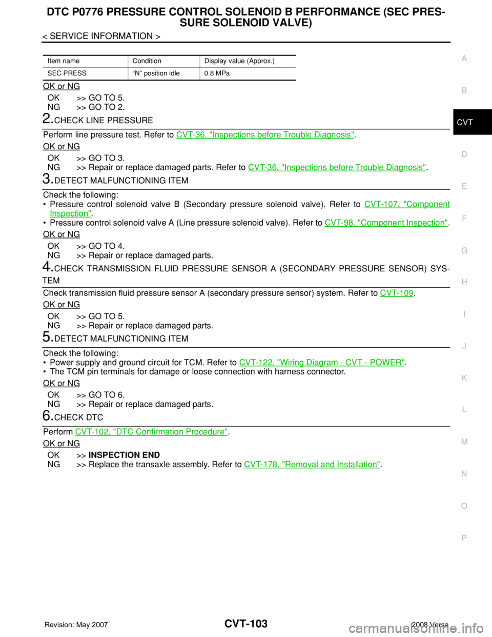
Item name Condition Display value (Approx.)
PRI PRESS “N” position idle 0.4 MPa
Name Connector Terminal ConditionVoltage
(Approx.)
Transmission
fluid pressure
sensor B (Pri-
mary pressure
sensor)E32 41 - Ground “N” position idle 0.7 V
SCIA1922E
Page 942 of 2771

DTC P0776 PRESSURE CONTROL SOLENOID B PERFORMANCE (SEC PRES-
SURE SOLENOID VALVE)
CVT-103
< SERVICE INFORMATION >
D
E
F
G
H
I
J
K
L
MA
B
CVT
N
O
P
OK or NG
OK >> GO TO 5.
NG >> GO TO 2.
2.CHECK LINE PRESSURE
Perform line pressure test. Refer to CVT-36, "
Inspections before Trouble Diagnosis".
OK or NG
OK >> GO TO 3.
NG >> Repair or replace damaged parts. Refer to CVT-36, "
Inspections before Trouble Diagnosis".
3.DETECT MALFUNCTIONING ITEM
Check the following:
• Pressure control solenoid valve B (Secondary pressure solenoid valve). Refer to CVT-107, "
Component
Inspection".
• Pressure control solenoid valve A (Line pressure solenoid valve). Refer to CVT-98, "
Component Inspection".
OK or NG
OK >> GO TO 4.
NG >> Repair or replace damaged parts.
4.CHECK TRANSMISSION FLUID PRESSURE SENSOR A (SECONDARY PRESSURE SENSOR) SYS-
TEM
Check transmission fluid pressure sensor A (secondary pressure sensor) system. Refer to CVT-109
.
OK or NG
OK >> GO TO 5.
NG >> Repair or replace damaged parts.
5.DETECT MALFUNCTIONING ITEM
Check the following:
• Power supply and ground circuit for TCM. Refer to CVT-122, "
Wiring Diagram - CVT - POWER".
• The TCM pin terminals for damage or loose connection with harness connector.
OK or NG
OK >> GO TO 6.
NG >> Repair or replace damaged parts.
6.CHECK DTC
Perform CVT-102, "
DTC Confirmation Procedure".
OK or NG
OK >>INSPECTION END
NG >> Replace the transaxle assembly. Refer to CVT-178, "
Removal and Installation".
Item name Condition Display value (Approx.)
SEC PRESS “N” position idle 0.8 MPa
Page 946 of 2771

DTC P0778 PRESSURE CONTROL SOLENOID B ELECTRICAL (SEC PRES-
SURE SOLENOID VALVE)
CVT-107
< SERVICE INFORMATION >
D
E
F
G
H
I
J
K
L
MA
B
CVT
N
O
P
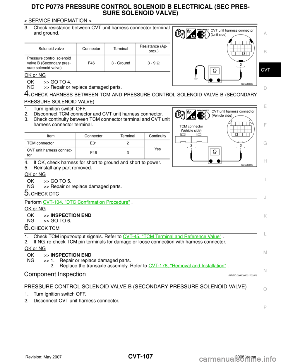
3. Check resistance between CVT unit harness connector terminal
and ground.
OK or NG
OK >> GO TO 4.
NG >> Repair or replace damaged parts.
4.CHECK HARNESS BETWEEN TCM AND PRESSURE CONTROL SOLENOID VALVE B (SECONDARY
PRESSURE SOLENOID VALVE)
1. Turn ignition switch OFF.
2. Disconnect TCM connector and CVT unit harness connector.
3. Check continuity between TCM connector terminal and CVT unit
harness connector terminal.
4. If OK, check harness for short to ground and short to power.
5. Reinstall any part removed.
OK or NG
OK >> GO TO 5.
NG >> Repair or replace damaged parts.
5.CHECK DTC
Perform CVT-104, "
DTC Confirmation Procedure" .
OK or NG
OK >>INSPECTION END
NG >> GO TO 6.
6.CHECK TCM
1. Check TCM input/output signals. Refer to CVT-45, "
TCM Terminal and Reference Value" .
2. If NG, re-check TCM pin terminals for damage or loose connection with harness connector.
OK or NG
OK >>INSPECTION END
NG >> 1. Repair or replace damaged parts.
2. Replace the transaxle assembly. Refer to CVT-178, "
Removal and Installation" .
Component InspectionINFOID:0000000001703572
PRESSURE CONTROL SOLENOID VALVE B (SECONDARY PRESSURE SOLENOID VALVE)
1. Turn ignition switch OFF.
2. Disconnect CVT unit harness connector.
Solenoid valve Connector TerminalResistance (Ap-
prox.)
Pressure control solenoid
valve B (Secondary pres-
sure solenoid valve) F46 3 - Ground 3 - 9 Ω
SCIA4688E
Item Connector Terminal Continuity
TCM connector E31 2
Ye s
CVT unit harness connec-
torF46 3
SCIA4689E
Page 947 of 2771
CVT-108
< SERVICE INFORMATION >
DTC P0778 PRESSURE CONTROL SOLENOID B ELECTRICAL (SEC PRES-
SURE SOLENOID VALVE)
3. Check resistance between CVT unit harness connector terminal
and ground.
4. If NG, replace the transaxle assembly. Refer to CVT-178,
"Removal and Installation" .
Solenoid Valve Connector TerminalResistance (Ap-
prox.)
Pressure control sole-
noid valve B (Secondary
pressure solenoid valve) F46 3 - Ground 3 - 9 Ω
SCIA4688E
Page 951 of 2771

CVT-112
< SERVICE INFORMATION >
DTC P0840 TRANSMISSION FLUID PRESSURE SENSOR A CIRCUIT (SEC
PRESSURE SENSOR)
OK >> Replace TCM. Refer to CVT-8, "Service After Replacing TCM and Transaxle Assembly" .
NG >> Repair open circuit or short to ground or short to power in harness or connectors.
4.CHECK HARNESS BETWEEN TCM AND TRANSMISSION FLUID PRESSURE SENSOR A (SECOND-
ARY PRESSURE SENSOR)
1. Turn ignition switch OFF.
2. Disconnect TCM connector and CVT unit harness connector.
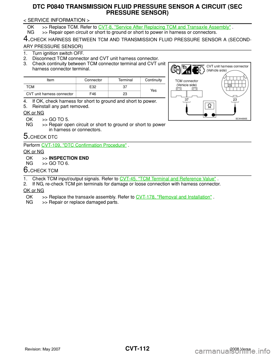
3. Check continuity between TCM connector terminal and CVT unit
harness connector terminal.
4. If OK, check harness for short to ground and short to power.
5. Reinstall any part removed.
OK or NG
OK >> GO TO 5.
NG >> Repair open circuit or short to ground or short to power
in harness or connectors.
5.CHECK DTC
Perform CVT-109, "
DTC Confirmation Procedure" .
OK or NG
OK >>INSPECTION END
NG >> GO TO 6.
6.CHECK TCM
1. Check TCM input/output signals. Refer to CVT-45, "
TCM Terminal and Reference Value" .
2. If NG, re-check TCM pin terminals for damage or loose connection with harness connector.
OK or NG
OK >> Replace the transaxle assembly. Refer to CVT-178, "Removal and Installation" .
NG >> Repair or replace damaged parts.
Item Connector Terminal Continuity
TCM E32 37
Ye s
CVT unit harness connector F46 23
SCIA4690E
Page 953 of 2771

CVT-114
< SERVICE INFORMATION >
DTC P0841 PRESSURE SENSOR FUNCTION
Without CONSULT-III
1. Start engine.
2. Check voltage between TCM connector terminals and ground.
OK or NG
OK >> GO TO 6.
NG >> GO TO 3.
3.CHECK LINE PRESSURE
Perform line pressure test. Refer to CVT-36, "
Inspections before Trouble Diagnosis".
OK or NG
OK >> GO TO 4.
NG >> Repair or replace damaged parts. Refer to CVT-36, "
Inspections before Trouble Diagnosis".
4.CHECK TRANSMISSION FLUID PRESSURE SENSOR A (SECONDARY PRESSURE SENSOR) SYS-
TEM AND TRANSMISSION FLUID PRESSURE SENSOR B (PRIMARY PRESSURE SENSOR) SYSTEM
Check transmission fluid pressure sensor A (secondary pressure sensor) system and transmission fluid pres-
sure sensor B (primary pressure sensor) system. Refer to CVT-109
, CVT-115.
OK or NG
OK >> GO TO 5.
NG >> Repair or replace damaged parts.
5.DETECT MALFUNCTIONING ITEM
Check the following:
• Pressure control solenoid valve A (Line pressure solenoid valve). Refer to CVT-98, "
Component Inspection".
• Pressure control solenoid valve B (Secondary pressure solenoid valve). Refer to CVT-107, "
Component
Inspection".
• Step motor. Refer to CVT-140, "
Component Inspection".
OK or NG6
OK >> GO TO 6.
NG >> Repair or replace damaged parts.
6.CHECK DTC
Perform CVT-113, "
DTC Confirmation Procedure".
OK or NG
OK >>INSPECTION END
NG >> Replace TCM or transaxle assembly. Refer to CVT-178, "
Removal and Installation".
Item name Condition Display value (Approx.)
PRI HYDR SEN
“N” position idle0.7 V
SEC HYDR SEN 1.0 V
Name Connector Terminal ConditionVoltage
(Approx.)
Transmission fluid
pressure sensor B
(Primary pres-
sure sensor)
E3241 - Ground
“N” position idle0.7 V
Transmission fluid
pressure sensor A
(Secondary pres-
sure sensor)37 - Ground 1.0 V
SCIA6879E