2008 NISSAN TIIDA Transaxle Assembly
[x] Cancel search: Transaxle AssemblyPage 1752 of 2771
ENGINE ASSEMBLY
EM-75
< SERVICE INFORMATION >
C
D
E
F
G
H
I
J
K
L
MA
EM
N
P O
• When installation directions are specified, install parts according to the directions. Refer to EM-72, "Compo-
nent".
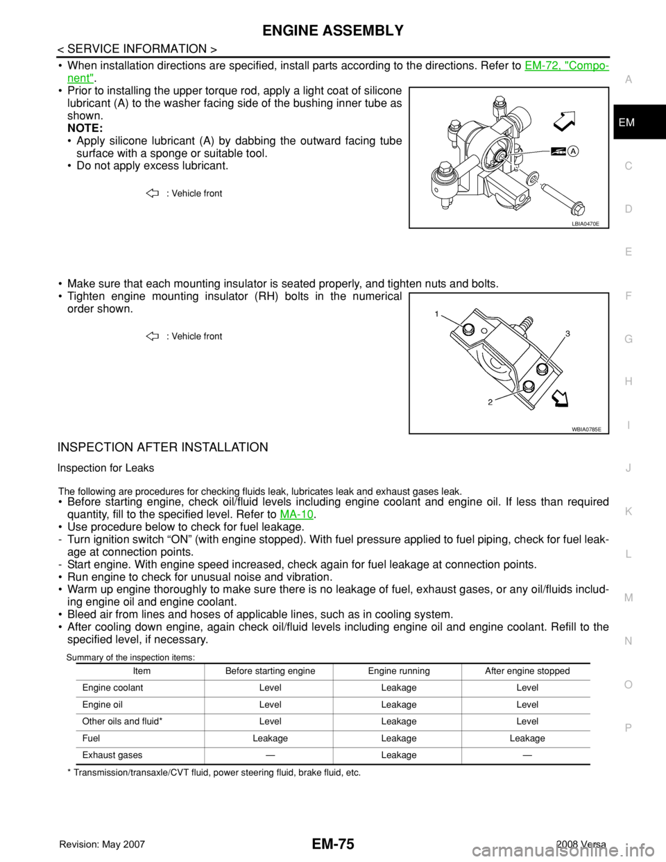
• Prior to installing the upper torque rod, apply a light coat of silicone
lubricant (A) to the washer facing side of the bushing inner tube as
shown.
NOTE:
• Apply silicone lubricant (A) by dabbing the outward facing tube
surface with a sponge or suitable tool.
• Do not apply excess lubricant.
• Make sure that each mounting insulator is seated properly, and tighten nuts and bolts.
• Tighten engine mounting insulator (RH) bolts in the numerical
order shown.
INSPECTION AFTER INSTALLATION
Inspection for Leaks
The following are procedures for checking fluids leak, lubricates leak and exhaust gases leak.
• Before starting engine, check oil/fluid levels including engine coolant and engine oil. If less than required
quantity, fill to the specified level. Refer to MA-10
.
• Use procedure below to check for fuel leakage.
- Turn ignition switch “ON” (with engine stopped). With fuel pressure applied to fuel piping, check for fuel leak-
age at connection points.
- Start engine. With engine speed increased, check again for fuel leakage at connection points.
• Run engine to check for unusual noise and vibration.
• Warm up engine thoroughly to make sure there is no leakage of fuel, exhaust gases, or any oil/fluids includ-
ing engine oil and engine coolant.
• Bleed air from lines and hoses of applicable lines, such as in cooling system.
• After cooling down engine, again check oil/fluid levels including engine oil and engine coolant. Refill to the
specified level, if necessary.
Summary of the inspection items:
* Transmission/transaxle/CVT fluid, power steering fluid, brake fluid, etc.: Vehicle front
LBIA0470E
: Vehicle front
WBIA0785E
Item Before starting engine Engine running After engine stopped
Engine coolant Level Leakage Level
Engine oil Level Leakage Level
Other oils and fluid* Level Leakage Level
Fuel Leakage Leakage Leakage
Exhaust gases — Leakage —
Page 1754 of 2771
CYLINDER BLOCK
EM-77
< SERVICE INFORMATION >
C
D
E
F
G
H
I
J
K
L
MA
EM
N
P O
Disassembly and AssemblyINFOID:0000000001702510
DISASSEMBLY
1. Remove engine and transaxle assembly from vehicle, separate transaxle from engine. Refer to EM-72.
2. Install engine to engine stand as follows;
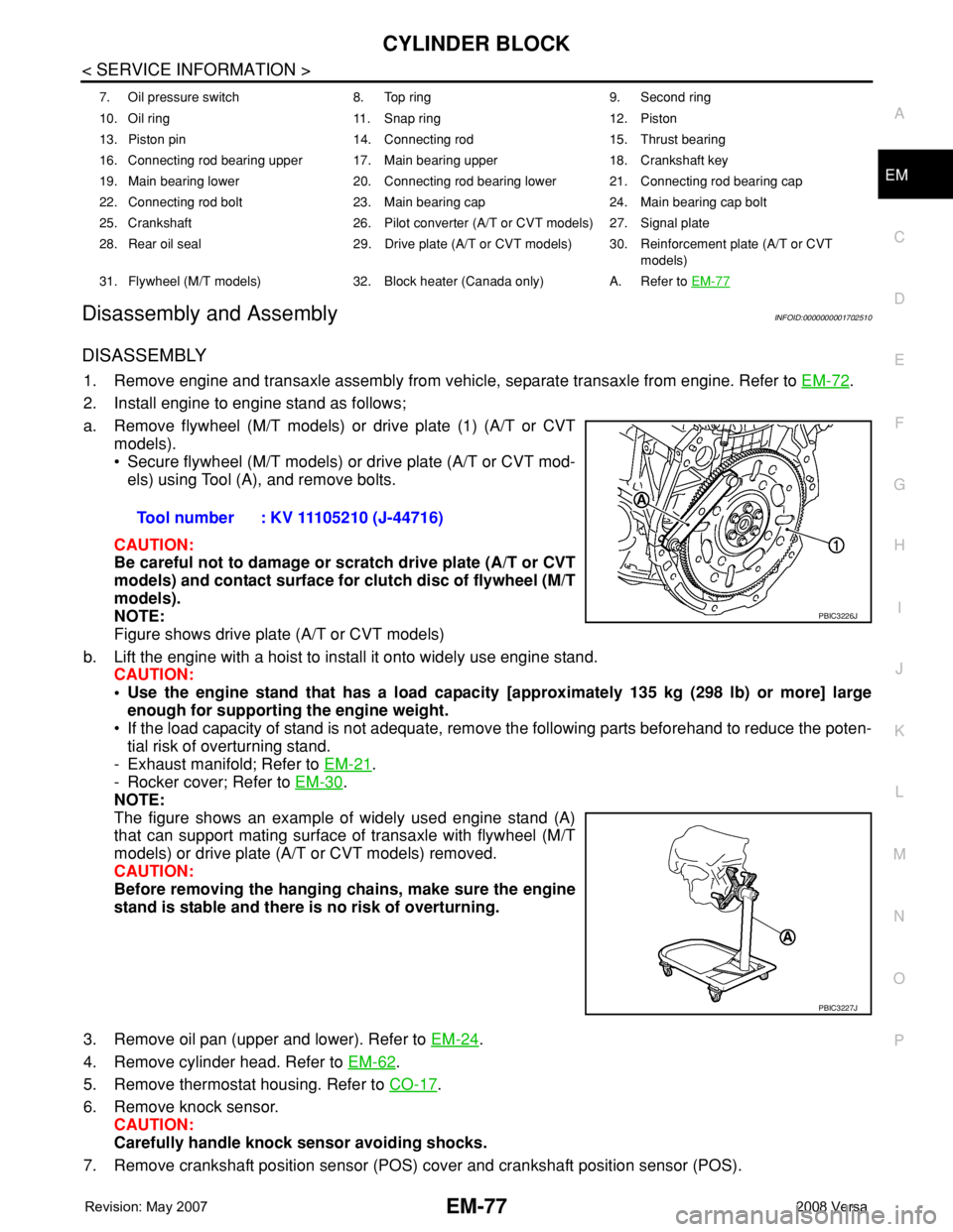
a. Remove flywheel (M/T models) or drive plate (1) (A/T or CVT
models).
• Secure flywheel (M/T models) or drive plate (A/T or CVT mod-
els) using Tool (A), and remove bolts.
CAUTION:
Be careful not to damage or scratch drive plate (A/T or CVT
models) and contact surface for clutch disc of flywheel (M/T
models).
NOTE:
Figure shows drive plate (A/T or CVT models)
b. Lift the engine with a hoist to install it onto widely use engine stand.
CAUTION:
• Use the engine stand that has a load capacity [approximately 135 kg (298 lb) or more] large
enough for supporting the engine weight.
• If the load capacity of stand is not adequate, remove the following parts beforehand to reduce the poten-
tial risk of overturning stand.
- Exhaust manifold; Refer to EM-21
.
- Rocker cover; Refer to EM-30
.
NOTE:
The figure shows an example of widely used engine stand (A)
that can support mating surface of transaxle with flywheel (M/T
models) or drive plate (A/T or CVT models) removed.
CAUTION:
Before removing the hanging chains, make sure the engine
stand is stable and there is no risk of overturning.
3. Remove oil pan (upper and lower). Refer to EM-24
.
4. Remove cylinder head. Refer to EM-62
.
5. Remove thermostat housing. Refer to CO-17
.
6. Remove knock sensor.
CAUTION:
Carefully handle knock sensor avoiding shocks.
7. Remove crankshaft position sensor (POS) cover and crankshaft position sensor (POS).
7. Oil pressure switch 8. Top ring 9. Second ring
10. Oil ring 11. Snap ring 12. Piston
13. Piston pin 14. Connecting rod 15. Thrust bearing
16. Connecting rod bearing upper 17. Main bearing upper 18. Crankshaft key
19. Main bearing lower 20. Connecting rod bearing lower 21. Connecting rod bearing cap
22. Connecting rod bolt 23. Main bearing cap 24. Main bearing cap bolt
25. Crankshaft 26. Pilot converter (A/T or CVT models) 27. Signal plate
28. Rear oil seal 29. Drive plate (A/T or CVT models) 30. Reinforcement plate (A/T or CVT
models)
31. Flywheel (M/T models) 32. Block heater (Canada only) A. Refer to EM-77
Tool number : KV 11105210 (J-44716)
PBIC3226J
PBIC3227J
Page 1805 of 2771
FRONT DRIVE SHAFT
FAX-9
< SERVICE INFORMATION >
C
E
F
G
H
I
J
K
L
MA
B
FA X
N
O
P
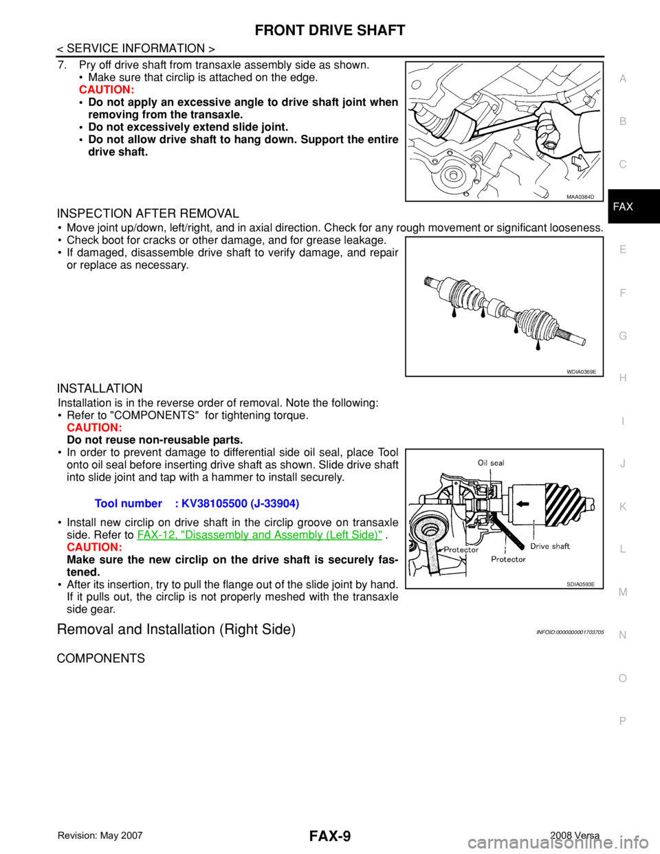
7. Pry off drive shaft from transaxle assembly side as shown.
• Make sure that circlip is attached on the edge.
CAUTION:
• Do not apply an excessive angle to drive shaft joint when
removing from the transaxle.
• Do not excessively extend slide joint.
• Do not allow drive shaft to hang down. Support the entire
drive shaft.
INSPECTION AFTER REMOVAL
• Move joint up/down, left/right, and in axial direction. Check for any rough movement or significant looseness.
• Check boot for cracks or other damage, and for grease leakage.
• If damaged, disassemble drive shaft to verify damage, and repair
or replace as necessary.
INSTALLATION
Installation is in the reverse order of removal. Note the following:
• Refer to "COMPONENTS" for tightening torque.
CAUTION:
Do not reuse non-reusable parts.
• In order to prevent damage to differential side oil seal, place Tool
onto oil seal before inserting drive shaft as shown. Slide drive shaft
into slide joint and tap with a hammer to install securely.
• Install new circlip on drive shaft in the circlip groove on transaxle
side. Refer to FAX-12, "
Disassembly and Assembly (Left Side)" .
CAUTION:
Make sure the new circlip on the drive shaft is securely fas-
tened.
• After its insertion, try to pull the flange out of the slide joint by hand.
If it pulls out, the circlip is not properly meshed with the transaxle
side gear.
Removal and Installation (Right Side)INFOID:0000000001703705
COMPONENTS
MAA0384D
WDIA0369E
Tool number : KV38105500 (J-33904)
SDIA0593E
Page 1806 of 2771
FAX-10
< SERVICE INFORMATION >
FRONT DRIVE SHAFT
REMOVAL
1. Remove wheel and tire using power tool. Refer to WT-6, "Rotation" .
2. Remove wheel sensor from steering knuckle. Refer to BRC-32, "
Removal and Installation".
CAUTION:
Do not pull on wheel sensor harness.
3. Remove transverse link ball joint nut and bolt. Then, remove transverse link from steering knuckle.
4. Remove cotter pin, then loosen hub lock nut using power tool.
CAUTION:
Temporarily leave the hub lock nut installed to prevent damage to threads.
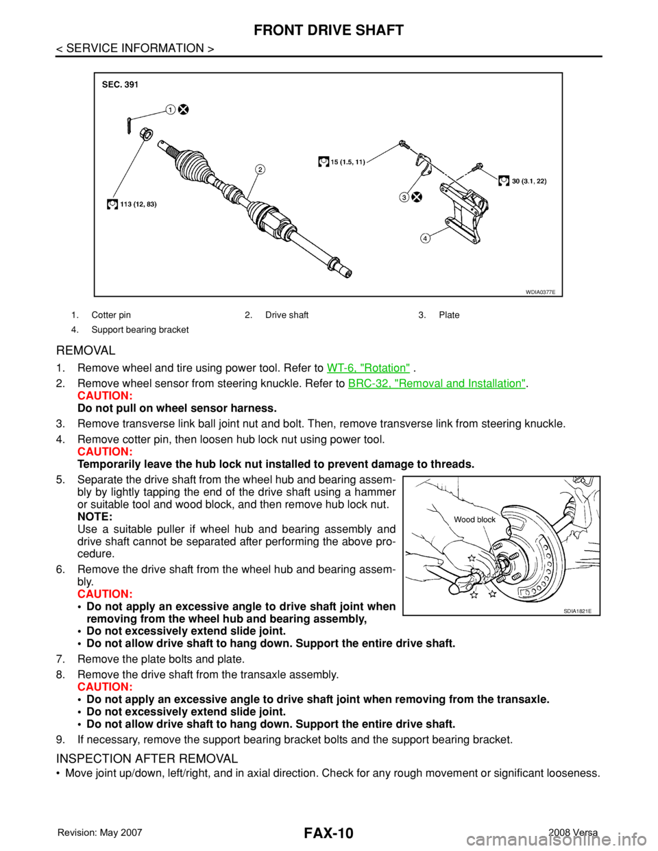
5. Separate the drive shaft from the wheel hub and bearing assem-
bly by lightly tapping the end of the drive shaft using a hammer
or suitable tool and wood block, and then remove hub lock nut.
NOTE:
Use a suitable puller if wheel hub and bearing assembly and
drive shaft cannot be separated after performing the above pro-
cedure.
6. Remove the drive shaft from the wheel hub and bearing assem-
bly.
CAUTION:
• Do not apply an excessive angle to drive shaft joint when
removing from the wheel hub and bearing assembly,
• Do not excessively extend slide joint.
• Do not allow drive shaft to hang down. Support the entire drive shaft.
7. Remove the plate bolts and plate.
8. Remove the drive shaft from the transaxle assembly.
CAUTION:
• Do not apply an excessive angle to drive shaft joint when removing from the transaxle.
• Do not excessively extend slide joint.
• Do not allow drive shaft to hang down. Support the entire drive shaft.
9. If necessary, remove the support bearing bracket bolts and the support bearing bracket.
INSPECTION AFTER REMOVAL
• Move joint up/down, left/right, and in axial direction. Check for any rough movement or significant looseness.
1. Cotter pin 2. Drive shaft 3. Plate
4. Support bearing bracket
WDIA0377E
SDIA1821E
Page 1808 of 2771
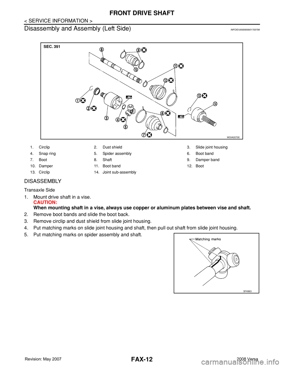
FAX-12
< SERVICE INFORMATION >
FRONT DRIVE SHAFT
Disassembly and Assembly (Left Side)
INFOID:0000000001703706
DISASSEMBLY
Transaxle Side
1. Mount drive shaft in a vise.
CAUTION:
When mounting shaft in a vise, always use copper or aluminum plates between vise and shaft.
2. Remove boot bands and slide the boot back.
3. Remove circlip and dust shield from slide joint housing.
4. Put matching marks on slide joint housing and shaft, then pull out shaft from slide joint housing.
5. Put matching marks on spider assembly and shaft.
1. Circlip 2. Dust shield 3. Slide joint housing
4. Snap ring 5. Spider assembly 6. Boot band
7. Boot 8. Shaft 9. Damper band
10. Damper 11. Boot band 12. Boot
13. Circlip 14. Joint sub-assembly
WDIA0370E
SFA963
Page 1809 of 2771
FRONT DRIVE SHAFT
FAX-13
< SERVICE INFORMATION >
C
E
F
G
H
I
J
K
L
MA
B
FA X
N
O
P
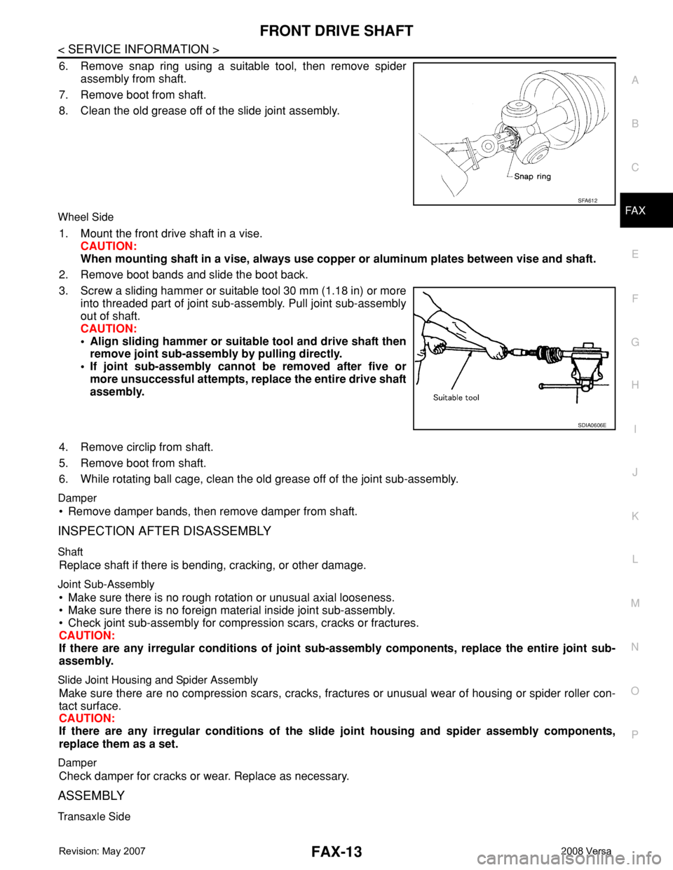
6. Remove snap ring using a suitable tool, then remove spider
assembly from shaft.
7. Remove boot from shaft.
8. Clean the old grease off of the slide joint assembly.
Wheel Side
1. Mount the front drive shaft in a vise.
CAUTION:
When mounting shaft in a vise, always use copper or aluminum plates between vise and shaft.
2. Remove boot bands and slide the boot back.
3. Screw a sliding hammer or suitable tool 30 mm (1.18 in) or more
into threaded part of joint sub-assembly. Pull joint sub-assembly
out of shaft.
CAUTION:
• Align sliding hammer or suitable tool and drive shaft then
remove joint sub-assembly by pulling directly.
• If joint sub-assembly cannot be removed after five or
more unsuccessful attempts, replace the entire drive shaft
assembly.
4. Remove circlip from shaft.
5. Remove boot from shaft.
6. While rotating ball cage, clean the old grease off of the joint sub-assembly.
Damper
• Remove damper bands, then remove damper from shaft.
INSPECTION AFTER DISASSEMBLY
Shaft
Replace shaft if there is bending, cracking, or other damage.
Joint Sub-Assembly
• Make sure there is no rough rotation or unusual axial looseness.
• Make sure there is no foreign material inside joint sub-assembly.
• Check joint sub-assembly for compression scars, cracks or fractures.
CAUTION:
If there are any irregular conditions of joint sub-assembly components, replace the entire joint sub-
assembly.
Slide Joint Housing and Spider Assembly
Make sure there are no compression scars, cracks, fractures or unusual wear of housing or spider roller con-
tact surface.
CAUTION:
If there are any irregular conditions of the slide joint housing and spider assembly components,
replace them as a set.
Damper
Check damper for cracks or wear. Replace as necessary.
ASSEMBLY
Transaxle Side
SFA612
SDIA0606E
Page 1813 of 2771
FRONT DRIVE SHAFT
FAX-17
< SERVICE INFORMATION >
C
E
F
G
H
I
J
K
L
MA
B
FA X
N
O
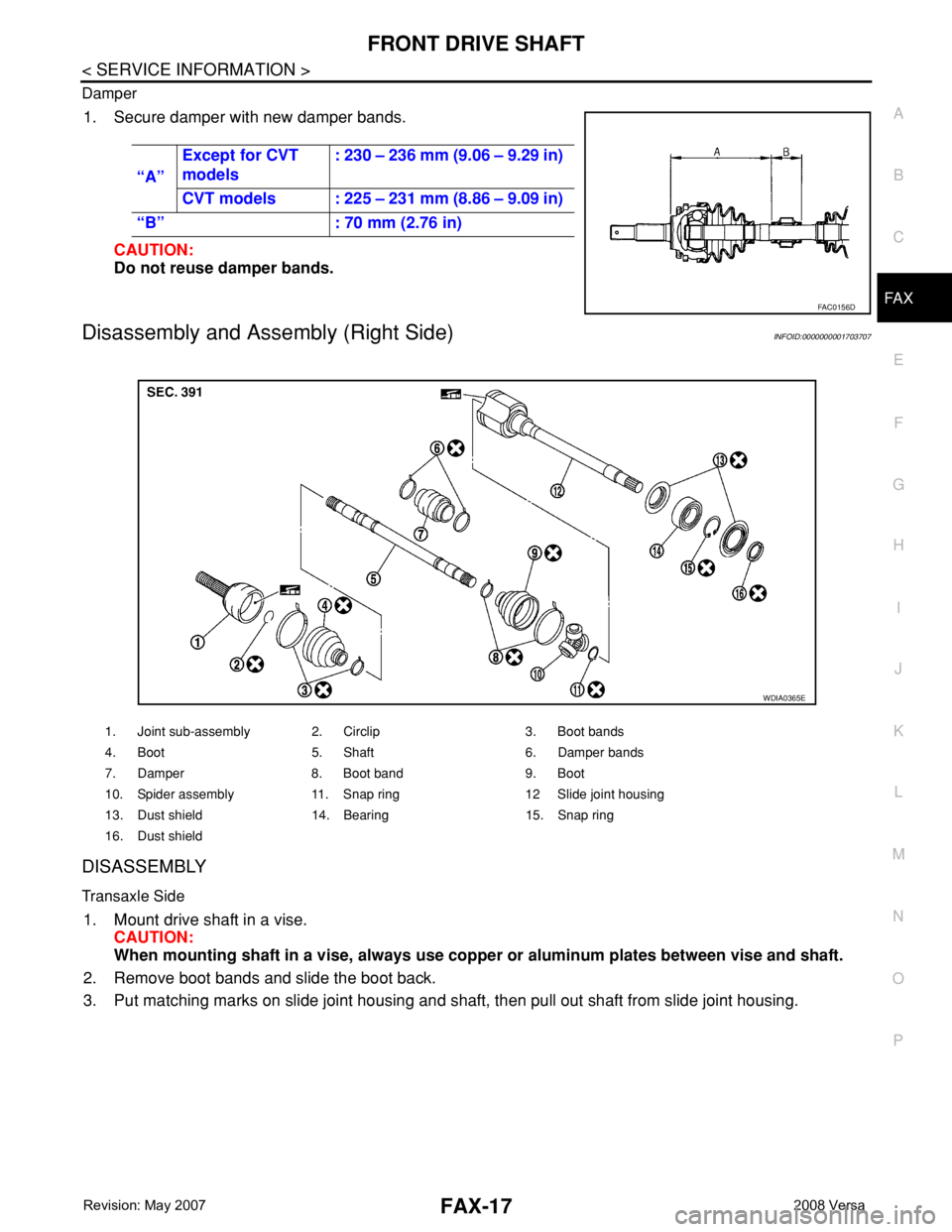
P Damper
1. Secure damper with new damper bands.
CAUTION:
Do not reuse damper bands.
Disassembly and Assembly (Right Side)INFOID:0000000001703707
DISASSEMBLY
Transaxle Side
1. Mount drive shaft in a vise.
CAUTION:
When mounting shaft in a vise, always use copper or aluminum plates between vise and shaft.
2. Remove boot bands and slide the boot back.
3. Put matching marks on slide joint housing and shaft, then pull out shaft from slide joint housing. “A”Except for CVT
models: 230 – 236 mm (9.06 – 9.29 in)
CVT models : 225 – 231 mm (8.86 – 9.09 in)
“B” : 70 mm (2.76 in)
FAC0156D
1. Joint sub-assembly 2. Circlip 3. Boot bands
4. Boot 5. Shaft 6. Damper bands
7. Damper 8. Boot band 9. Boot
10. Spider assembly 11. Snap ring 12 Slide joint housing
13. Dust shield 14. Bearing 15. Snap ring
16. Dust shield
WDIA0365E
Page 1815 of 2771
FRONT DRIVE SHAFT
FAX-19
< SERVICE INFORMATION >
C
E
F
G
H
I
J
K
L
MA
B
FA X
N
O
P
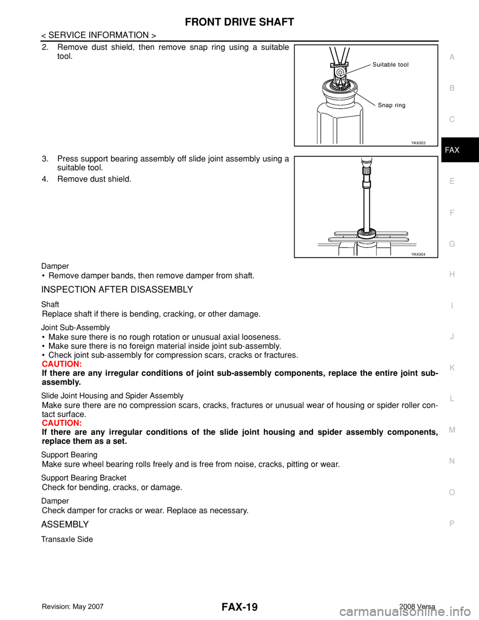
2. Remove dust shield, then remove snap ring using a suitable
tool.
3. Press support bearing assembly off slide joint assembly using a
suitable tool.
4. Remove dust shield.
Damper
• Remove damper bands, then remove damper from shaft.
INSPECTION AFTER DISASSEMBLY
Shaft
Replace shaft if there is bending, cracking, or other damage.
Joint Sub-Assembly
• Make sure there is no rough rotation or unusual axial looseness.
• Make sure there is no foreign material inside joint sub-assembly.
• Check joint sub-assembly for compression scars, cracks or fractures.
CAUTION:
If there are any irregular conditions of joint sub-assembly components, replace the entire joint sub-
assembly.
Slide Joint Housing and Spider Assembly
Make sure there are no compression scars, cracks, fractures or unusual wear of housing or spider roller con-
tact surface.
CAUTION:
If there are any irregular conditions of the slide joint housing and spider assembly components,
replace them as a set.
Support Bearing
Make sure wheel bearing rolls freely and is free from noise, cracks, pitting or wear.
Support Bearing Bracket
Check for bending, cracks, or damage.
Damper
Check damper for cracks or wear. Replace as necessary.
ASSEMBLY
Transaxle Side
YA X 0 0 3
YA X 0 0 4