Page 347 of 2771
ASSEMBLY
AT-335
< SERVICE INFORMATION >
D
E
F
G
H
I
J
K
L
MA
B
AT
N
O
P
b. Back off anchor end pin two and a half turns.
c. Tighten lock nut while holding anchor end pin. Refer to AT-230,
"Component".
14. Apply compressed air into oil holes of transaxle case and check
operation of brake band.
15. Install final drive assembly on transaxle case.
16. Install differential lubricant tube (1) and clips (2) on converter
housing.
: Bolt (3)
17. Tighten differential lubricant tube fitting bolts to the specified
torque. Refer to AT-230, "
Component".
SAT395D
SAT396D
SAT397D
SAT228F
SCIA7817E
Page 348 of 2771
AT-336
< SERVICE INFORMATION >
ASSEMBLY
18. Install O-ring on differential oil port of transaxle case.
19. Apply locking sealant (loctite #518) to transaxle case as shown
in the figure.
: Inside of transaxle case
CAUTION:
Completely remove all moisture, oil and old sealant, etc.
from the transaxle case and converter housing mating sur-
faces.
20. Install converter housing on transaxle case.
21. Install bracket on converter housing.
22. Tighten converter housing fitting bolts (1) and (2) to the specified
torque. Refer to AT-230, "
Component".
23. Install plug or speedometer pinion according to the following
procedures.
a. With ABS
i. Install O-ring (3) to plug (1).
ii. Install plug (1) to converter housing (2).
: Bolt (1)
SCIA3281E
“A”: 3 - 5 mm (0.12 - 0.20 in)
“B”: 8 mm (0.31 in) R
“C”: 1.5 mm (0.059 in) dia.
“D”: 4 mm (0.16 in)
SCIA7089E
Bolt 1 2
Bolt length
[mm (in)]
32.8 (1.291) 40 (1.57)
Number of bolts 10 10
SCIA7970E
SCIA7747E
Page 349 of 2771
ASSEMBLY
AT-337
< SERVICE INFORMATION >
D
E
F
G
H
I
J
K
L
MA
B
AT
N
O
P
b. Without ABS
i. Install O-ring (3) to speedometer pinion (1).
ii. Install speedometer pinion (1) to converter housing (2).
: Bolt (1)
24. Tighten plug or speedometer pinion fitting bolt to the specified torque. Refer to AT-230, "
Component".
25. Install accumulator pistons.
a. Install O-rings (1) on servo release accumulator piston (2) and
N-D accumulator piston (3). Refer to AT-343, "
Accumulator".
b. Install return springs (1), servo release accumulator piston (2)
and N-D accumulator piston (3) into transaxle case (4). Refer to
AT-343, "
Accumulator".
26. Install lip seals (1) for band servo oil holes on transaxle case.
27. Install control valve assembly on transaxle case.
a. Install O-ring on terminal body.
CAUTION:
• Do not reuse O-ring.
• Apply ATF to O-ring.
SCIA7462E
SCIA6033J
SCIA6042J
SCIA5895J
Page 350 of 2771
AT-338
< SERVICE INFORMATION >
ASSEMBLY
b. Insert manual valve into control valve assembly.
CAUTION:
Be careful not to drop manual valve.
c. Set manual shaft in “N” position.
d. Install control valve assembly on transaxle case while aligning
manual valve (2) with manual plate (1).
e. Install terminal body (2) into transaxle case by pushing it.
f. Install snap ring (1) to terminal body (2).
g. Tighten bolts A, B and C to the specified torque. Refer to AT-230, "
Component".
Bolt length, number and location:
28. Install oil pan.
a. Attach magnets on oil pan.
SCIA3999E
SCIA7090E
SCIA6030J
Bolt symbol A B C
Bolt length “ ” [mm (in)]
40.0 mm
(1.575 in)33.0 mm
(1.299 in)43.5 mm
(1.713 in)
Number of bolts 5 6 2
SCIA5911J
Page 351 of 2771

ASSEMBLY
AT-339
< SERVICE INFORMATION >
D
E
F
G
H
I
J
K
L
MA
B
AT
N
O
P
b. Install oil pan gasket on transaxle case.
CAUTION:
• Completely remove all moisture, oil and old gasket, etc.
from the oil pan gasket mounting surface of transaxle
case.
• Do not reuse oil pan gasket.
c. Install oil pan on transaxle case.
CAUTION:
Completely remove all moisture, oil and old gasket, etc.
from the oil pan gasket mounting surface of oil pan.
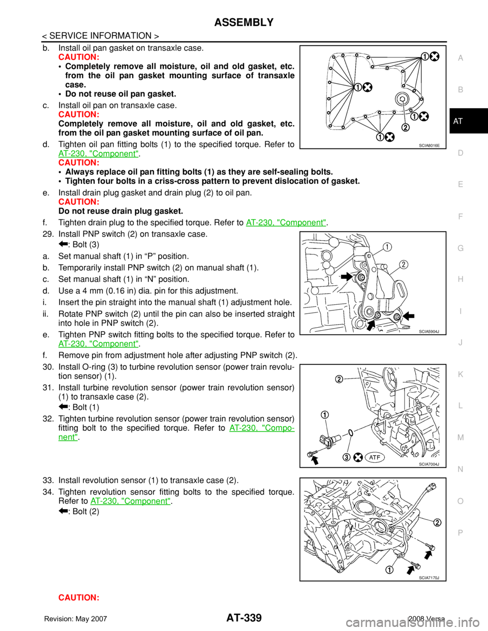
d. Tighten oil pan fitting bolts (1) to the specified torque. Refer to
AT-230, "
Component".
CAUTION:
• Always replace oil pan fitting bolts (1) as they are self-sealing bolts.
• Tighten four bolts in a criss-cross pattern to prevent dislocation of gasket.
e. Install drain plug gasket and drain plug (2) to oil pan.
CAUTION:
Do not reuse drain plug gasket.
f. Tighten drain plug to the specified torque. Refer to AT-230, "
Component".
29. Install PNP switch (2) on transaxle case.
: Bolt (3)
a. Set manual shaft (1) in “P” position.
b. Temporarily install PNP switch (2) on manual shaft (1).
c. Set manual shaft (1) in “N” position.
d. Use a 4 mm (0.16 in) dia. pin for this adjustment.
i. Insert the pin straight into the manual shaft (1) adjustment hole.
ii. Rotate PNP switch (2) until the pin can also be inserted straight
into hole in PNP switch (2).
e. Tighten PNP switch fitting bolts to the specified torque. Refer to
AT-230, "
Component".
f. Remove pin from adjustment hole after adjusting PNP switch (2).
30. Install O-ring (3) to turbine revolution sensor (power train revolu-
tion sensor) (1).
31. Install turbine revolution sensor (power train revolution sensor)
(1) to transaxle case (2).
: Bolt (1)
32. Tighten turbine revolution sensor (power train revolution sensor)
fitting bolt to the specified torque. Refer to AT-230, "
Compo-
nent".
33. Install revolution sensor (1) to transaxle case (2).
34. Tighten revolution sensor fitting bolts to the specified torque.
Refer to AT-230, "
Component".
: Bolt (2)
CAUTION:
SCIA8016E
SCIA5904J
SCIA7004J
SCIA7170J
Page 353 of 2771

SERVICE DATA AND SPECIFICATIONS (SDS)
AT-341
< SERVICE INFORMATION >
D
E
F
G
H
I
J
K
L
MA
B
AT
N
O
P
SERVICE DATA AND SPECIFICATIONS (SDS)
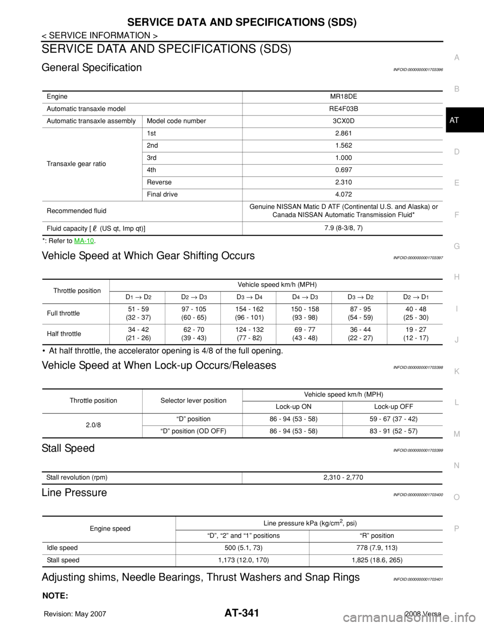
General SpecificationINFOID:0000000001703396
*: Refer to MA-10.
Vehicle Speed at Which Gear Shifting OccursINFOID:0000000001703397
• At half throttle, the accelerator opening is 4/8 of the full opening.
Vehicle Speed at When Lock-up Occurs/ReleasesINFOID:0000000001703398
Stall SpeedINFOID:0000000001703399
Line PressureINFOID:0000000001703400
Adjusting shims, Needle Bearings, Thrust Washers and Snap RingsINFOID:0000000001703401
NOTE:
EngineMR18DE
Automatic transaxle model RE4F03B
Automatic transaxle assembly Model code number 3CX0D
Transaxle gear ratio1st 2.861
2nd 1.562
3rd 1.000
4th 0.697
Reverse 2.310
Final drive 4.072
Recommended fluidGenuine NISSAN Matic D ATF (Continental U.S. and Alaska) or
Canada NISSAN Automatic Transmission Fluid*
Fluid capacity [ (US qt, Imp qt)]7.9 (8-3/8, 7)
Throttle positionVehicle speed km/h (MPH)
D1 → D2D2 → D3D3 → D4D4 → D3D3 → D2D2 → D1
Full throttle51 - 59
(32 - 37)97 - 105
(60 - 65)154 - 162
(96 - 101)150 - 158
(93 - 98)87 - 95
(54 - 59)40 - 48
(25 - 30)
Half throttle34 - 42
(21 - 26)62 - 70
(39 - 43)124 - 132
(77 - 82)69 - 77
(43 - 48)36 - 44
(22 - 27)19 - 27
(12 - 17)
Throttle position Selector lever positionVehicle speed km/h (MPH)
Lock-up ON Lock-up OFF
2.0/8“D” position 86 - 94 (53 - 58) 59 - 67 (37 - 42)
“D” position (OD OFF) 86 - 94 (53 - 58) 83 - 91 (52 - 57)
Stall revolution (rpm)2,310 - 2,770
Engine speedLine pressure kPa (kg/cm2, psi)
“D”, “2” and “1” positions “R” position
Idle speed 500 (5.1, 73) 778 (7.9, 113)
Stall speed 1,173 (12.0, 170) 1,825 (18.6, 265)
Page 803 of 2771

CL-2
< SERVICE INFORMATION >
PRECAUTIONS
SERVICE INFORMATION
PRECAUTIONS
Precaution for Supplemental Restraint System (SRS) "AIR BAG" and "SEAT BELT
PRE-TENSIONER"
INFOID:0000000001703112
The Supplemental Restraint System such as “AIR BAG” and “SEAT BELT PRE-TENSIONER”, used along
with a front seat belt, helps to reduce the risk or severity of injury to the driver and front passenger for certain
types of collision. This system includes seat belt switch inputs and dual stage front air bag modules. The SRS
system uses the seat belt switches to determine the front air bag deployment, and may only deploy one front
air bag, depending on the severity of a collision and whether the front occupants are belted or unbelted.
Information necessary to service the system safely is included in the SRS and SB section of this Service Man-
ual.
WARNING:
• To avoid rendering the SRS inoperative, which could increase the risk of personal injury or death in
the event of a collision which would result in air bag inflation, all maintenance must be performed by
an authorized NISSAN/INFINITI dealer.
• Improper maintenance, including incorrect removal and installation of the SRS, can lead to personal
injury caused by unintentional activation of the system. For removal of Spiral Cable and Air Bag
Module, see the SRS section.
• Do not use electrical test equipment on any circuit related to the SRS unless instructed to in this
Service Manual. SRS wiring harnesses can be identified by yellow and/or orange harnesses or har-
ness connectors.
Precaution for Procedure without Cowl Top CoverINFOID:0000000001843684
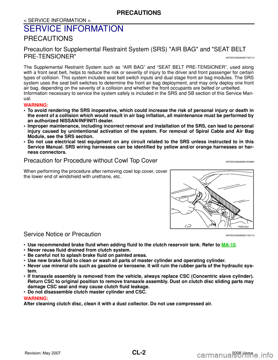
When performing the procedure after removing cowl top cover, cover
the lower end of windshield with urethane, etc.
Service Notice or PrecautionINFOID:0000000001703113
•Use recommended brake fluid when adding fluid to the clutch reservoir tank. Refer to MA-10.
•Never reuse fluid drained from clutch system.
•Be careful not to splash brake fluid on painted areas.
•Use new brake fluid to clean or wash all parts of master cylinder and operating cylinder.
•Never use mineral oils such as gasoline or kerosene. It will ruin the rubber parts of the hydraulic sys-
tem.
•If transaxle assembly is removed from the vehicle, always replace CSC (Concentric slave cylinder).
Return CSC to original position to remove transaxle assembly. Dust on clutch disc sliding parts may
damage CSC seal and may cause clutch fluid leakage.
•Do not disassemble clutch master cylinder and CSC.
WARNING:
After cleaning clutch disc, clean it with a dust collector. Do not use compressed air.
PIIB3706J
Page 812 of 2771

CSC (CONCENTRIC SLAVE CYLINDER)
CL-11
< SERVICE INFORMATION >
D
E
F
G
H
I
J
K
L
MA
B
CL
N
O
P
CSC (CONCENTRIC SLAVE CYLINDER)
Removal and InstallationINFOID:0000000001703121
CAUTION:
• If transaxle assembly is removed from the vehicle, always replace CSC (Concentric slave cylinder).
Return CSC insert to original position to remove transaxle assembly. Dust on clutch disc sliding
parts may damage CSC seal and may cause clutch fluid leakage.
• Keep painted surface of the body and other parts free of clutch fluid. If it spills, wipe up immediately
and wash the affected area with water.
REMOVAL
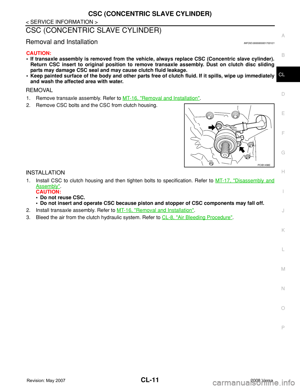
1. Remove transaxle assembly. Refer to MT-16, "Removal and Installation".
2. Remove CSC bolts and the CSC from clutch housing.
INSTALLATION
1. Install CSC to clutch housing and then tighten bolts to specification. Refer to MT-17, "Disassembly and
Assembly".
CAUTION:
• Do not reuse CSC.
• Do not insert and operate CSC because piston and stopper of CSC components may fall off.
2. Install transaxle assembly. Refer to MT-16, "
Removal and Installation".
3. Bleed the air from the clutch hydraulic system. Refer to CL-8, "
Air Bleeding Procedure".
PCIB1498E