Page 1 of 2771

-1
QUICK REFERENCE INDEX
AGENERAL INFORMATIONGIGeneral Information
BENGINEEMEngine Mechanical
LUEngine Lubrication System
COEngine Cooling System
ECEngine Control System
FLFuel System
EXExhaust System
ACCAccelerator Control System
CTRANSMISSION/
TRANSAXLECLClutch System
MTManual Transaxle
ATAutomatic Transaxle
CVTCVT
DDRIVELINE/AXLEFAXFront Axle
RAXRear Axle
ESUSPENSIONFSUFront Suspension
RSURear Suspension
WTRoad Wheels & Tires
FBRAKESBRBrake System
PBParking Brake System
BRCBrake Control System
GSTEERINGPSPower Steering System
STCSteering Control System
HRESTRAINTSSBSeat Belts
SRSSupplemental Restraint System (SRS)
IBODYBLBody, Lock & Security System
GWGlasses, Window System & Mirrors
RFRoof
EIExterior & Interior
IPInstrument Panel
SESeat
JAIR CONDITIONERMTCManual Air Conditioner
KELECTRICALSCStarting & Charging System
LTLighting System
DIDriver Information System
WWWiper, Washer & Horn
BCSBody Control System
LANLAN System
AVAudio Visual, Navigation & Telephone System
ACSAuto Cruise Control System
PGPower Supply, Ground & Circuit Elements
LMAINTENANCEMAMaintenance
Edition: May 2007
Revision: May 2007
Publication No. SM8E-1C11U0
B
D
© 2007 NISSAN NORTH AMERICA, INC.
All rights reserved. No part of this Service Manual may be reproduced or stored in a retrieval system, or transmitted in any
form, or by any means, electronic, mechanical, photo-copying, recording or otherwise, without the prior written permission
of Nissan North America Inc.
A
C
E
F
G
H
I
J
K
L
M
Page 31 of 2771
A/T CONTROL SYSTEM
AT-19
< SERVICE INFORMATION >
D
E
F
G
H
I
J
K
L
MA
B
AT
N
O
P
A/T CONTROL SYSTEM
Cross-Sectional ViewINFOID:0000000001703161
Shift MechanismINFOID:0000000001703162
CONSTRUCTION
1. Converter housing 2. Oil pump 3. Brake band
4. Reverse clutch 5. High clutch 6. Front planetary gear
7. Low one-way clutch 8. Rear planetary gear 9. Forward clutch
10. Overrun clutch 11. Low & reverse brake 12. Output gear
13. Band servo piston 14. Reverse clutch drum 15. Side cover
16. Idler gear 17. Forward one-way clutch 18. Transaxle case
19. Reduction pinion gear 20. Final gear 21. Differential case
22. Input shaft 23. Torque converter
SCIA7938E
Page 37 of 2771
A/T CONTROL SYSTEM
AT-25
< SERVICE INFORMATION >
D
E
F
G
H
I
J
K
L
MA
B
AT
N
O
P “D
4” (OD) Position
SAT379J
•High clutch
•Brake band
•Forward clutch (Does not affect power
transmission)Input power is transmitted to front carrier through high clutch.
This front carrier turns around the sun gear which is fixed by brake band and makes
front internal gear (output) turn faster.
Engine brakeAt D
4 position, there is no one-way clutch in the power transaxle line and engine brake
can be obtained when decelerating.
Page 38 of 2771
AT-26
< SERVICE INFORMATION >
A/T CONTROL SYSTEM
“R” Position
SAT380J
•Reverse clutch
•Low & reverse brakeFront planetary carrier is stationary because of the operation of low and reverse brake.
Input power is transmitted to front sun gear through reverse clutch, which drives front
internal gear in the opposite direction.
Engine brakeAs there is no one-way clutch in the power transaxle line, engine brake can be obtained
when decelerating.
Page 235 of 2771
ON-VEHICLE SERVICE
AT-223
< SERVICE INFORMATION >
D
E
F
G
H
I
J
K
L
MA
B
AT
N
O
P
3. Disconnect turbine revolution sensor (power train revolution
sensor) harness connector (1).
4. Remove turbine revolution sensor (power train revolution sen-
sor) bolt.
: Bolt (1)
5. Remove turbine revolution sensor (power train revolution sen-
sor) (2) from A/T.
6. Remove O-ring from turbine revolution sensor (power train revo-
lution sensor) (2).
Installation
Installation is in the reverse order of removal.
CAUTION:
• Do not reuse O-ring.
• Apply ATF to O-ring.
Differential Side Oil SealINFOID:0000000001703370
COMPONENTS
REMOVAL AND INSTALLATION
Removal
1. Remove front drive shaft. Refer to FA X - 8.
2. Remove differential side oil seals using a flat-bladed screw-
driver.
CAUTION:
Be careful not to scratch transaxle case and converter
housing.
Installation
WCIA0658E
1. A/T 2. LH differential side oil seal 3. RH differential side oil seal
SCIA8021E
SCIA4857E
Page 239 of 2771

TRANSAXLE ASSEMBLY
AT-227
< SERVICE INFORMATION >
D
E
F
G
H
I
J
K
L
MA
B
AT
N
O
P
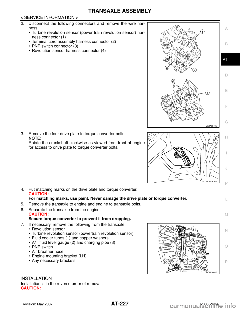
2. Disconnect the following connectors and remove the wire har-
ness.
• Turbine revolution sensor (power train revolution sensor) har-
ness connector (1)
• Terminal cord assembly harness connector (2)
• PNP switch connector (3)
• Revolution sensor harness connector (4)
3. Remove the four drive plate to torque converter bolts.
NOTE:
Rotate the crankshaft clockwise as viewed from front of engine
for access to drive plate to torque converter bolts.
4. Put matching marks on the drive plate and torque converter.
CAUTION:
For matching marks, use paint. Never damage the drive plate or torque converter.
5. Remove the transaxle to engine and engine to transaxle bolts.
6. Separate the transaxle from the engine.
CAUTION:
Secure torque converter to prevent it from dropping.
7. If necessary, remove the following from the transaxle:
• Revolution sensor
• Turbine revolution sensor (powertrain revolution sensor)
• Fluid cooler tubes (1) and copper washers
• A/T fluid level gauge (2) and charging pipe (3)
• PNP switch
• Air breather hose
• Engine mounting bracket (LH)
• Any necessary brackets
INSTALLATION
Installation is in the reverse order of removal.
CAUTION:
WCIA0647E
WCIA0616E
WCIA0648E
Page 240 of 2771

AT-228
< SERVICE INFORMATION >
TRANSAXLE ASSEMBLY
• When replacing an engine or transmission you must make sure any dowels are installed correctly
during re-assembly.
• Improper alignment caused by missing dowels may cause vibration, oil leaks or breakage of drive
train components.
• Do not reuse O-rings and copper washers. Refer to "COMPONENTS".
• When turning crankshaft, turn it clockwise as viewed from the front of the engine.
• When tightening the bolts for the torque converter while securing the crankshaft pulley bolt, be sure
to confirm the tightening torque of the crankshaft pulley bolt. Refer to EM-37
.
• After converter is installed to drive plate, rotate crankshaft several turns to check that transaxle
rotates freely without binding.
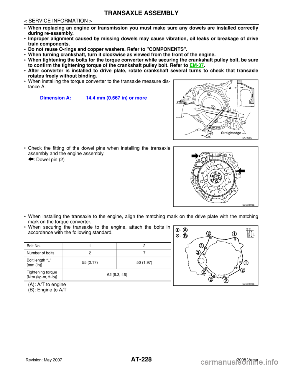
• When installing the torque converter to the transaxle measure dis-
tance A.
• Check the fitting of the dowel pins when installing the transaxle
assembly and the engine assembly.
: Dowel pin (2)
• When installing the transaxle to the engine, align the matching mark on the drive plate with the matching
mark on the torque converter.
• When securing the transaxle to the engine, attach the bolts in
accordance with the following standard.
(A): A/T to engine
(B): Engine to A/TDimension A: 14.4 mm (0.567 in) or more
SAT430D
SCIA7698E
Bolt No. 1 2
Number of bolts 2 7
Bolt length “L”
[mm (in)]55 (2.17) 50 (1.97)
Tightening torque
[N·m (kg-m, ft-lb)]62 (6.3, 46)
SCIA7685E
Page 262 of 2771
AT-250
< SERVICE INFORMATION >
DISASSEMBLY
37. Remove front planetary carrier and low one-way clutch according to the following procedures.
a. Remove snap ring using a flat-bladed screwdriver.
b. Remove low one-way clutch (1) and front planetary carrier (2) as
a set from transaxle case.
c. Check that low one-way clutch rotates counter-clockwise around
front planetary carrier. Then try to turn it clockwise and check
that it is locked.
•Replace low one-way clutch if necessary.
d. Remove low one-way clutch from front planetary carrier by turn-
ing it in the direction of unlock.
•Inspect low one-way clutch, and replace if damaged or
worn.
e. Remove needle bearing (1) from front planetary carrier (2).
•Inspect needle bearing (1) and front planetary carrier (2),
and replace if damaged or worn.
SCIA3633E
SCIA5896J
SAT048D
SCIA6047J