Page 885 of 2771

CVT-46
< SERVICE INFORMATION >
TROUBLE DIAGNOSIS
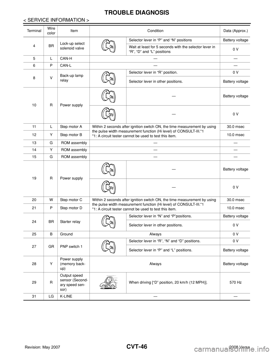
4BRLock-up select
solenoid valveSelector lever in “P” and “N” positions Battery voltage
Wait at least for 5 seconds with the selector lever in
“R”, “D” and “L” positions0 V
5 L CAN-H — —
6 P CAN-L — —
8VBack-up lamp
relaySelector lever in “R” position. 0 V
Selector lever in other positions. Battery voltage
10 R Power supply— Battery voltage
—0 V
11 L Step motor A Within 2 seconds after ignition switch ON, the time measurement by using
the pulse width measurement function (Hi level) of CONSULT-III.*1
*1: A circuit tester cannot be used to test this item.30.0 msec
12 Y Step motor B10.0 msec
13 G ROM assembly — —
14 Y ROM assembly — —
15 G ROM assembly — —
19 R Power supply— Battery voltage
—0 V
20 W Step motor C Within 2 seconds after ignition switch ON, the time measurement by using
the pulse width measurement function (Hi level) of CONSULT-III.*1
*1: A circuit tester cannot be used to test this item.30.0 msec
21 P Step motor D10.0 msec
24 BR Starter relaySelector lever in “N” and “P”positions. Battery voltage
Selector lever in other positions. 0 V
25 B Ground Always 0 V
27 GR PNP switch 1Selector lever in “R”, “N” and “D” positions. 0 V
Selector lever in “P” and “L” positions. Battery voltage
28 YPower supply
(memory back-
up)Always Battery voltage
29 ROutput speed
sensor (Second-
ary speed sen-
sor)When driving [“D” position, 20 km/h (12 MPH)]. 570 Hz
31 LG K-LINE — — Te r m i n a lWire
colorItem Condition Data (Approx.)
Page 1379 of 2771

DTC P0340 CMP SENSOR (PHASE)
EC-305
< SERVICE INFORMATION >
C
D
E
F
G
H
I
J
K
L
MA
EC
N
P O
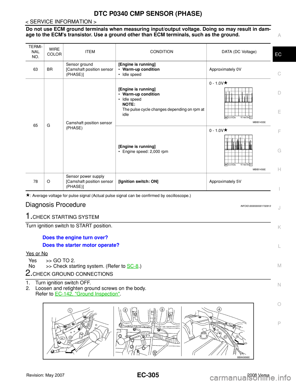
Do not use ECM ground terminals when measuring input/output voltage. Doing so may result in dam-
age to the ECM's transistor. Use a ground other than ECM terminals, such as the ground.
: Average voltage for pulse signal (Actual pulse signal can be confirmed by oscilloscope.)
Diagnosis ProcedureINFOID:0000000001702813
1.CHECK STARTING SYSTEM
Turn ignition switch to START position.
Ye s o r N o
Yes >> GO TO 2.
No >> Check starting system. (Refer to SC-8
.)
2.CHECK GROUND CONNECTIONS
1. Turn ignition switch OFF.
2. Loosen and retighten ground screws on the body.
Refer to EC-142, "
Ground Inspection".
TERMI-
NAL
NO.WIRE
COLORITEM CONDITION DATA (DC Voltage)
63 BRSensor ground
[Camshaft position sensor
(PHASE)][Engine is running]
•Warm-up condition
• Idle speedApproximately 0V
65 GCamshaft position sensor
(PHASE)[Engine is running]
•Warm-up condition
• Idle speed
NOTE:
The pulse cycle changes depending on rpm at
idle0 - 1.0V
[Engine is running]
• Engine speed: 2,000 rpm0 - 1.0V
78 OSensor power supply
[Camshaft position sensor
(PHASE)][Ignition switch: ON]Approximately 5V
MBIB1455E
MBIB1456E
Does the engine turn over?
Does the starter motor operate?
BBIA0698E
Page 2456 of 2771

IPDM E/R (INTELLIGENT POWER DISTRIBUTION MODULE ENGINE ROOM)
PG-23
< SERVICE INFORMATION >
C
D
E
F
G
H
I
J
L
MA
B
PG
N
O
P
Terminal and Reference Value for IPDM E/RINFOID:0000000001704703
Te r m i n a lWire
colorSignal nameSignal
input/
outputMeasuring condition
Reference value
(Approx.) Ignition
switchOperation or condition
1 R Battery power supply Input OFF — Battery voltage
2 G Battery power supply Input OFF — Battery voltage
3YECM Relay Output—Ignition switch ON or START Battery voltage
Ignition switch OFF or ACC 0V
4GECM relay Output—Ignition switch ON or START Battery voltage
Ignition switch OFF or ACC 0V
6RDaytime light relay
controlInput ON Daytime light system active. Less than battery voltage
Daytime light system inactive. Battery voltage
7 G ECM relay control Input —Ignition switch ON or START 0V
Ignition switch OFF or ACC Battery voltage
8GThrottle control motor
relayOutput —Ignition switch ON or START Battery voltage
Ignition switch OFF or ACC 0V
11 W A/C compressor OutputON or
STARTA/C switch ON or defrost A/C
switchBattery voltage
A/C switch OFF or defrost A/C
switch0V
12 OIgnition switch sup-
plied powerInput —OFF or ACC 0V
ON or START Battery voltage
14LG
(M/T)
R
(A/T
or
CVT)Fuse 49 Output —Ignition switch ON or START Battery voltage
Ignition switch OFF or ACC 0V
15 V Fuse 50 Output —Ignition switch ON or START Battery voltage
Ignition switch OFF or ACC 0V
16 BR Fuse 51 Output —Ignition switch ON or START Battery voltage
Ignition switch OFF or ACC 0V
17 Y Battery power supply Output — — Battery voltage
19 R Starter motor Output START — Battery voltage
20L
(with
A/C)
LG
(with-
out A/
C)Cooling fan relay-1 Output —Conditions correct for cooling
fan low operation.Battery voltage
Conditions not correct for
cooling fan low operation.0V
22 G Battery power supply Input — — Battery voltage
23 L Cooling fan relay-2 Input —Conditions correct for cooling
fan high operationBattery voltage
Conditions not correct for
cooling fan high operation0V
Page 2457 of 2771

PG-24
< SERVICE INFORMATION >
IPDM E/R (INTELLIGENT POWER DISTRIBUTION MODULE ENGINE ROOM)
24 Y Cooling fan relay-3 Output —Conditions correct for cooling
fan high operationBattery voltage
Conditions not correct for
cooling fan high operation0V
26 OTail lamp relay (park-
ing lamps)Output — Lighting switch in 2nd position Battery voltage
27 BRTail lamp relay (park-
ing lamps)Output — Lighting switch in 2nd position Battery voltage
28 GRTail lamp relay (park-
ing lamps)Output — Lighting switch in 2nd position Battery voltage
29 PTail lamp relay (park-
ing lamps)Output — Lighting switch in 2nd position Battery voltage
30
(A/T
only)R Fuse 54 Output —Ignition switch ON or START Battery voltage
Ignition switch OFF or ACC 0V
31 O Fuse 55 Output —Ignition switch ON or START Battery voltage
Ignition switch OFF or ACC 0V
32 LWiper high speed sig-
nalOutputON or
STARTWiper switchOFF, LO, INT 0V
HI Battery voltage
33 YWiper low speed sig-
nalOutputON or
STARTWiper switchOFF 0V
LO or INT Battery voltage
35 BRStarter relay (inhibit
switch)InputON or
STARTSelector lever in "P" or "N"
(CVT or A/T) or clutch pedal
depressed (M/T)Battery voltage
Selector lever any other posi-
tion (CVT or A/T) or clutch
pedal released (M/T)0V
36 BR Fuel pump relay Output —Ignition switch ON or START Battery voltage
Ignition switch OFF or ACC 0V
37 G Oil pressure switch InputON or
STARTEngine running and oil pres-
sure within specificationBattery voltage
Engine not running or oil pres-
sure below specification0V
38 R Wiper auto stop signal InputON or
STARTWipers not in park position Battery voltage
Wipers in park position 0V
39 B Ground Input — — 0V
40 P CAN-L — ON — —
41 L CAN-H — ON — —
45 R Horn relay control Input —Horn switch PUSHED, alarm
switch activated or door lock/
unlock is confirmed when op-
erating lock system via the
keyfob0V
Horn switch released, alarm
not active, keyfob not activeBattery voltage
46 YThrottle control motor
relay controlInput —Ignition switch ON or START 0V
Ignition switch OFF or ACC Battery voltage
47 GRFuel pump relay con-
trolInput —
Ignition switch ON or START 0V
Ignition switch OFF or ACC Battery voltage Te r m i n a lWire
colorSignal nameSignal
input/
outputMeasuring condition
Reference value
(Approx.) Ignition
switchOperation or condition