2008 NISSAN TIIDA Cylinder head
[x] Cancel search: Cylinder headPage 422 of 2771
BCS-6
< SERVICE INFORMATION >
BCM (BODY CONTROL MODULE)
• When CAN communication operation is detected, it switches to CAN communication status.
• When a state of the following switches changes, it switches to CAN communication state:
- Ignition switch
- Key switch (without Intelligent Key)
- Key switch and ignition knob switch (with Intelligent Key)
- Hazard switch
- Door lock/unlock switch
- Front door switch (LH, RH)
- Rear door switch (LH, RH)
- Back door lock assembly (Hatchback)
- Trunk key cylinder switch (Sedan)
- Trunk lamp switch and trunk release solenoid (Sedan)
- Combination switch (passing, lighting switch 1st position, front fog lamp)
- Keyfob (lock/unlock signal)
- Front door key cylinder switch LH
• When control performed only by BCM is required by switch, it shifts to CAN communication inactive
mode.
• Status of combination switch reading function is changed.
SYSTEMS CONTROLLED BY BCM DIRECTLY
• Power door lock system. Refer to BL-22 .
• Remote keyless entry system. Refer to BL-51
.
• Power window system. Refer to GW-18
. NOTE
• Sunroof system. Refer to RF-10. NOTE
• Room lamp timer. Refer to LT- 8 9 .
• Rear wiper and washer system. Refer to WW-24
.
NOTE:
Power supply only. No system control.
SYSTEMS CONTROLLED BY BCM AND IPDM E/R
• Panic system. Refer to BL-51 .
• Vehicle security (theft warning) system. Refer to BL-187
.
• NVIS(NATS) system. Refer to BL-210
.
• Headlamp, tail lamp and battery saver control systems. Refer to LT- 7 2
, LT- 4 or LT- 2 5 .
• Front fog lamp. Refer to LT- 3 9
.
• Front wiper and washer system. Refer to WW-3
.
• Rear window defogger system. Refer to GW-49
.
SYSTEMS CONTROLLED BY BCM AND COMBINATION METER
• Warning chime. Refer to DI-41 .
• Turn signal and hazard warning lamps. Refer to LT- 4 8
.
SYSTEMS CONTROLLED BY BCM AND INTELLIGENT KEY UNIT
• Intelligent Key system. Refer to BL-74 .
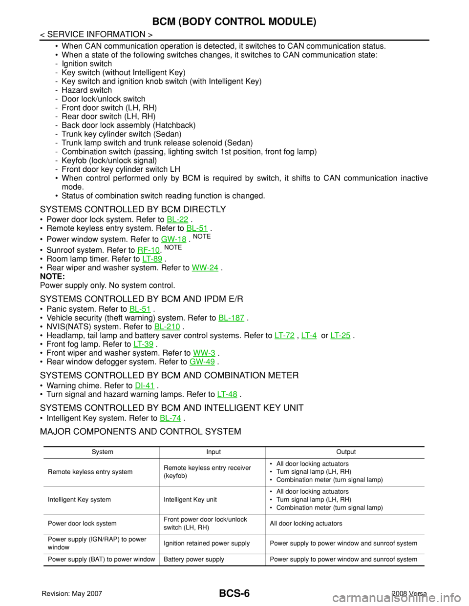
MAJOR COMPONENTS AND CONTROL SYSTEM
System Input Output
Remote keyless entry systemRemote keyless entry receiver
(keyfob)• All door locking actuators
• Turn signal lamp (LH, RH)
• Combination meter (turn signal lamp)
Intelligent Key system Intelligent Key unit• All door locking actuators
• Turn signal lamp (LH, RH)
• Combination meter (turn signal lamp)
Power door lock systemFront power door lock/unlock
switch (LH, RH)All door locking actuators
Power supply (IGN/RAP) to power
windowIgnition retained power supply Power supply to power window and sunroof system
Power supply (BAT) to power window Battery power supply Power supply to power window and sunroof system
Page 423 of 2771

BCM (BODY CONTROL MODULE)
BCS-7
< SERVICE INFORMATION >
C
D
E
F
G
H
I
J
L
MA
B
BCS
N
O
P
CAN Communication System DescriptionINFOID:0000000001704585
Refer to LAN-6, "System Description".
Panic alarm• Key switch
•KeyfobIPDM E/R
Vehicle security system• All door switches
•Keyfob
• Door lock/unlock switch
• Trunk key cylinder switch (Se-
dan)
• Front door key cylinder switch
LH• IPDM/ER
• Security indicator lamp
Battery saver control• Ignition switch
• Combination switchIPDM E/R
Headlamp Combination switch IPDM E/R
Tail lamp Combination switch IPDM E/R
Front fog lamp Combination switch IPDM E/R
Turn signal lamp Combination switch• Turn signal lamp
• Combination meter
Hazard lamp Hazard switch• Turn signal lamp
• Combination meter
Room lamp timer• Key switch
•Keyfob
• Main power window and door
lock/unlock switch
• Front door switch LH
• All door switchInterior room lamp
Back door switch signal (Hatchback) Back door lock assembly Luggage room lamp
Back door lock signal (Hatchback) Back door lock assembly Back door opener
Trunk lamp switch signalTrunk lamp switch and trunk re-
lease solenoidLuggage room lamp
Trunk lid opener signalTrunk lamp switch and trunk re-
lease solenoidTrunk lid opener
Key warning chime• Key switch
• Front door switch LHCombination meter (warning buzzer)
Light warning chime• Combination switch
• Key switch
• Front door switch LHCombination meter (warning buzzer)
Seat belt warning chime• Seat belt buckle switch LH
• Ignition switchCombination meter (warning buzzer)
Front wiper and washer system• Combination switch
• Ignition switchIPDM E/R
Rear window defogger Rear window defogger switch IPDM E/R
Rear wiper and washer system• Combination switch
• Ignition switchRear wiper motor
A/C switch signal Front air control ECM
Blower fan switch signal Front air control ECM
A/C indicator signal Front air control A/C indicator
Low tire pressure warning system Remote keyless entry receiver Combination meterSystem Input Output
Page 605 of 2771
TRUNK LID
BL-171
< SERVICE INFORMATION >
C
D
E
F
G
H
J
K
L
MA
B
BL
N
O
P
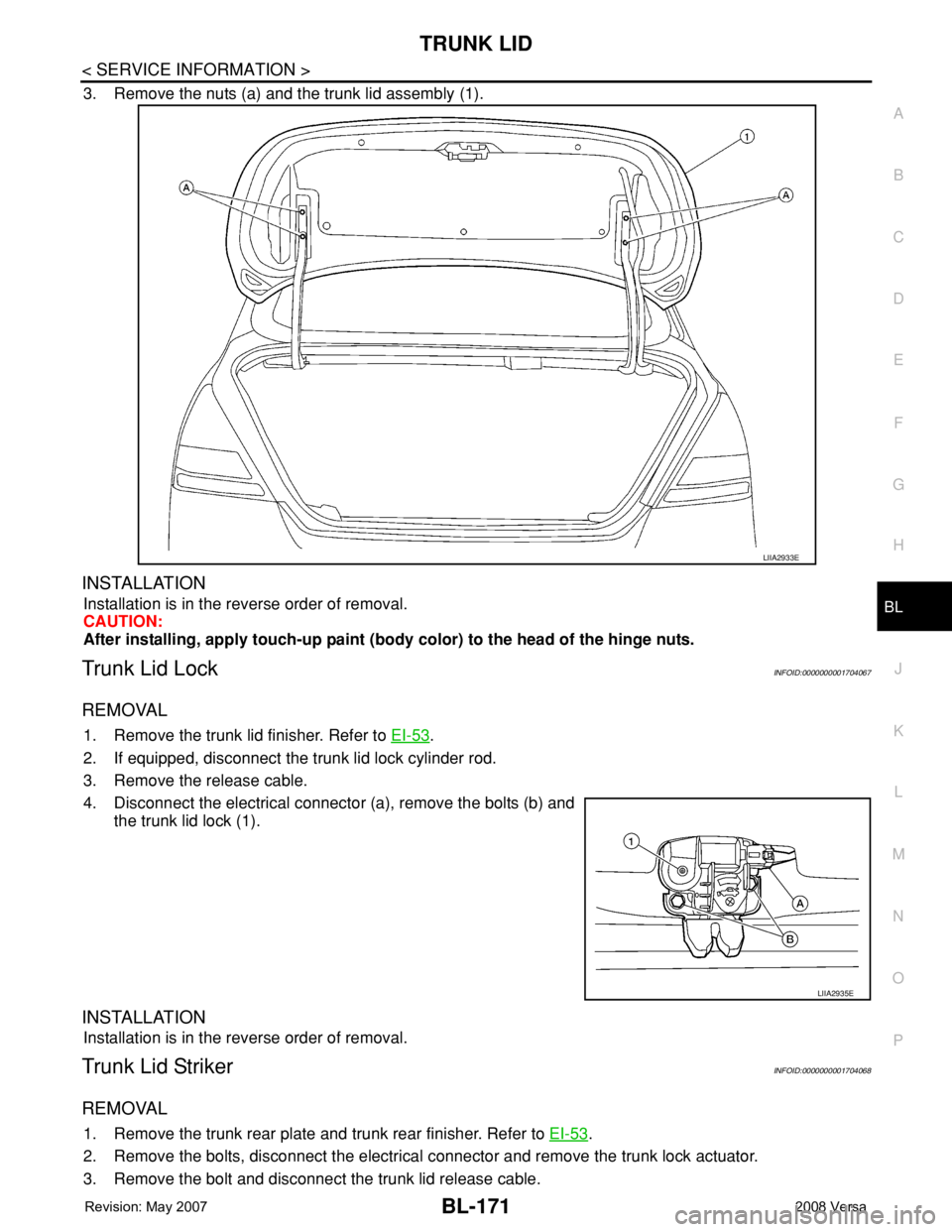
3. Remove the nuts (a) and the trunk lid assembly (1).
INSTALLATION
Installation is in the reverse order of removal.
CAUTION:
After installing, apply touch-up paint (body color) to the head of the hinge nuts.
Trunk Lid LockINFOID:0000000001704067
REMOVAL
1. Remove the trunk lid finisher. Refer to EI-53.
2. If equipped, disconnect the trunk lid lock cylinder rod.
3. Remove the release cable.
4. Disconnect the electrical connector (a), remove the bolts (b) and
the trunk lid lock (1).
INSTALLATION
Installation is in the reverse order of removal.
Trunk Lid StrikerINFOID:0000000001704068
REMOVAL
1. Remove the trunk rear plate and trunk rear finisher. Refer to EI-53.
2. Remove the bolts, disconnect the electrical connector and remove the trunk lock actuator.
3. Remove the bolt and disconnect the trunk lid release cable.
LIIA2933E
LIIA2935E
Page 622 of 2771
BL-188
< SERVICE INFORMATION >
VEHICLE SECURITY (THEFT WARNING) SYSTEM
System Description
INFOID:0000000001704084
DESCRIPTION
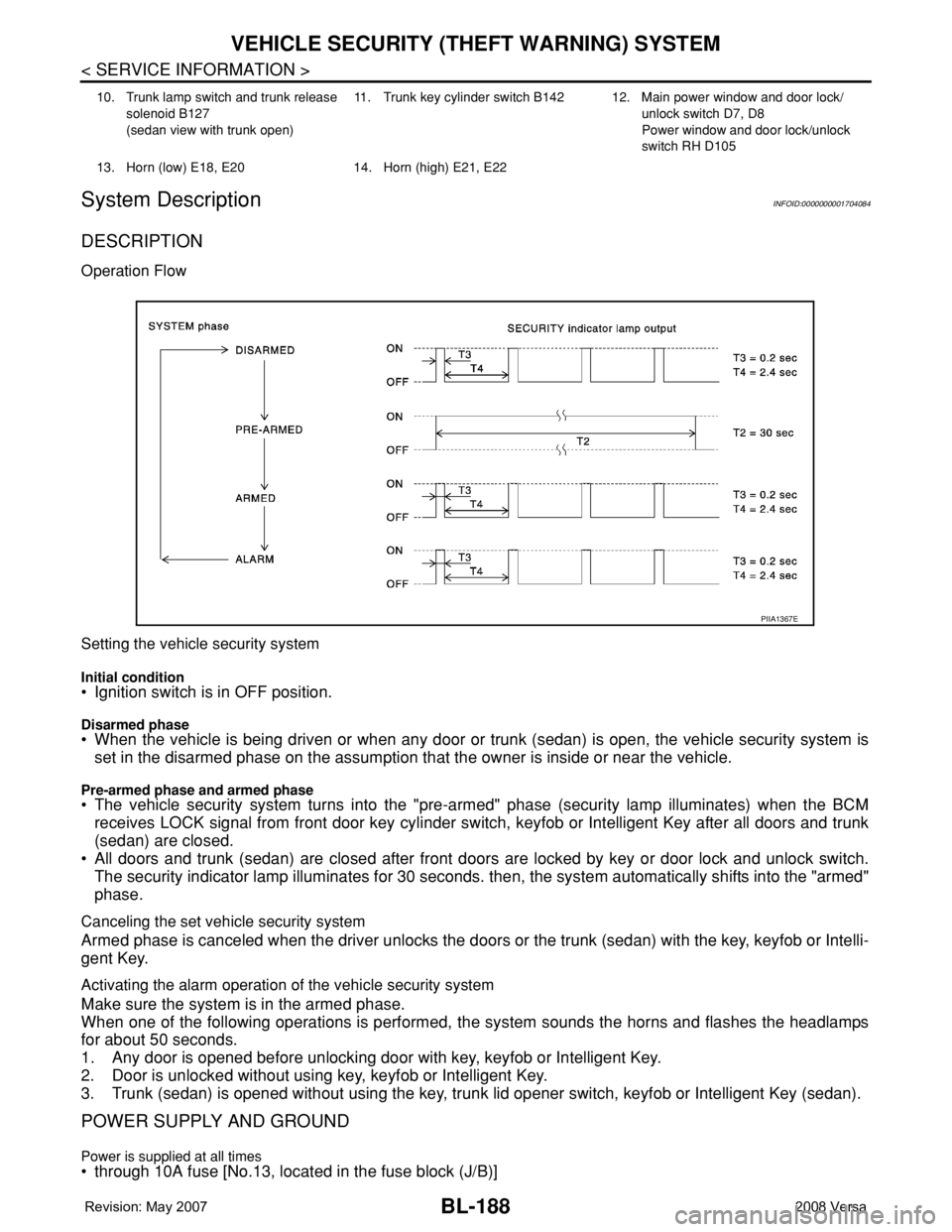
Operation Flow
Setting the vehicle security system
Initial condition• Ignition switch is in OFF position.
Disarmed phase• When the vehicle is being driven or when any door or trunk (sedan) is open, the vehicle security system is
set in the disarmed phase on the assumption that the owner is inside or near the vehicle.
Pre-armed phase and armed phase• The vehicle security system turns into the "pre-armed" phase (security lamp illuminates) when the BCM
receives LOCK signal from front door key cylinder switch, keyfob or Intelligent Key after all doors and trunk
(sedan) are closed.
• All doors and trunk (sedan) are closed after front doors are locked by key or door lock and unlock switch.
The security indicator lamp illuminates for 30 seconds. then, the system automatically shifts into the "armed"
phase.
Canceling the set vehicle security system
Armed phase is canceled when the driver unlocks the doors or the trunk (sedan) with the key, keyfob or Intelli-
gent Key.
Activating the alarm operation of the vehicle security system
Make sure the system is in the armed phase.
When one of the following operations is performed, the system sounds the horns and flashes the headlamps
for about 50 seconds.
1. Any door is opened before unlocking door with key, keyfob or Intelligent Key.
2. Door is unlocked without using key, keyfob or Intelligent Key.
3. Trunk (sedan) is opened without using the key, trunk lid opener switch, keyfob or Intelligent Key (sedan).
POWER SUPPLY AND GROUND
Power is supplied at all times• through 10A fuse [No.13, located in the fuse block (J/B)]
10. Trunk lamp switch and trunk release
solenoid B127
(sedan view with trunk open)11. Trunk key cylinder switch B142 12. Main power window and door lock/
unlock switch D7, D8
Power window and door lock/unlock
switch RH D105
13. Horn (low) E18, E20 14. Horn (high) E21, E22
PIIA1367E
Page 623 of 2771

VEHICLE SECURITY (THEFT WARNING) SYSTEM
BL-189
< SERVICE INFORMATION >
C
D
E
F
G
H
J
K
L
MA
B
BL
N
O
P
• to combination meter terminal 27 (security indicator lamp)
• through 40A fusible link (letter g, located in the fuse and fusible link box)
• to BCM terminal 70
• through 10A fuse [No. 8, located in the fuse block (J/B)]
• to BCM terminal 57
• through 10A fuse (No. 28, located in the fuse and fusible link box)
• to horn relay terminal 2
• through 15A fuse (No. 52, located in the IPDM E/R)
• to IPDM E/R internal CPU.
• through 20A fuse (No. 53, located in the IPDM E/R)
• to IPDM E/R internal CPU.
With the ignition switch in the ACC or ON position, power is supplied• through 10A fuse [No. 20, located in the fuse block (J/B)]
• to BCM terminal 11.
With the ignition switch in the ON or START position, power is supplied• through 10A fuse [No. 6, located in the fuse block (J/B)]
• to BCM terminal 38.
Ground is supplied• to BCM terminal 67
• through body grounds M57 and M61.
INITIAL CONDITION TO ACTIVATE THE SYSTEM
The operation of the vehicle security system is controlled by the doors and trunk (sedan).
To activate the vehicle security system, BCM must receive signals indicating the ignition switch is OFF, doors
and trunk (sedan) are closed and locked.
When a door or trunk (sedan) is open, BCM terminal 12, 13, 42, 43, 47 or 48 receives a ground signal from
each door or trunk switch. In addition to BCM, when back door is open, the Intelligent Key unit terminal 23
receives a ground signal from back door or trunk (sedan) through BCM terminal 30.
When front door LH is unlocked, BCM terminal 46 receives a signal from terminal 6 of main power window and
door lock/unlock switch.
When front door RH is unlocked, BCM terminal 46 receives a signal from terminal 2 of power window and door
lock/unlock switch RH.
VEHICLE SECURITY SYSTEM ALARM OPERATION
The vehicle security system is triggered by
• Opening a door without using the key, keyfob or Intelligent Key.
• Opening trunk without using the key, keyfob or Intelligent Key (sedan).
The vehicle security system will be triggered once the system is in armed phase,
• when BCM receives a ground signal at terminals 12, 13, 47, 48 (front or rear door switch), terminal 42
(sedan, trunk switch) or terminal 43 (hatchback, back door switch).
When the vehicle security system is triggered, ground is supplied intermittently
• from IPDM E/R terminal 45
• to horn relay terminal 1.
The headlamps flash and the horn sounds intermittently.
The alarm automatically turns off after 50 seconds, but will reactivate if the vehicle is tampered with again.
VEHICLE SECURITY SYSTEM DEACTIVATION
To deactivate the vehicle security system, a door or trunk (sedan) must be unlocked with the key, keyfob or
Intelligent Key.
When the key is used to unlock the driver door, BCM terminal 7 receives signal
• from terminal 3 of the front door key cylinder switch LH.
When the key is used to open the trunk (sedan), BCM terminal 41 receives signal
• from terminal 1 of the trunk key cylinder switch.
When the BCM receives an unlock signal from keyfob, Intelligent Key, front door key cylinder switch LH or
trunk key cylinder switch (sedan), the vehicle security system is deactivated (Disarmed phase).
PANIC ALARM OPERATION
Intelligent Key and remote keyless entry system may or may not operate vehicle security system (horn and
headlamps) as required.
When the remote keyless entry system is triggered, ground is supplied intermittently
Page 633 of 2771
VEHICLE SECURITY (THEFT WARNING) SYSTEM
BL-199
< SERVICE INFORMATION >
C
D
E
F
G
H
J
K
L
MA
B
BL
N
O
P
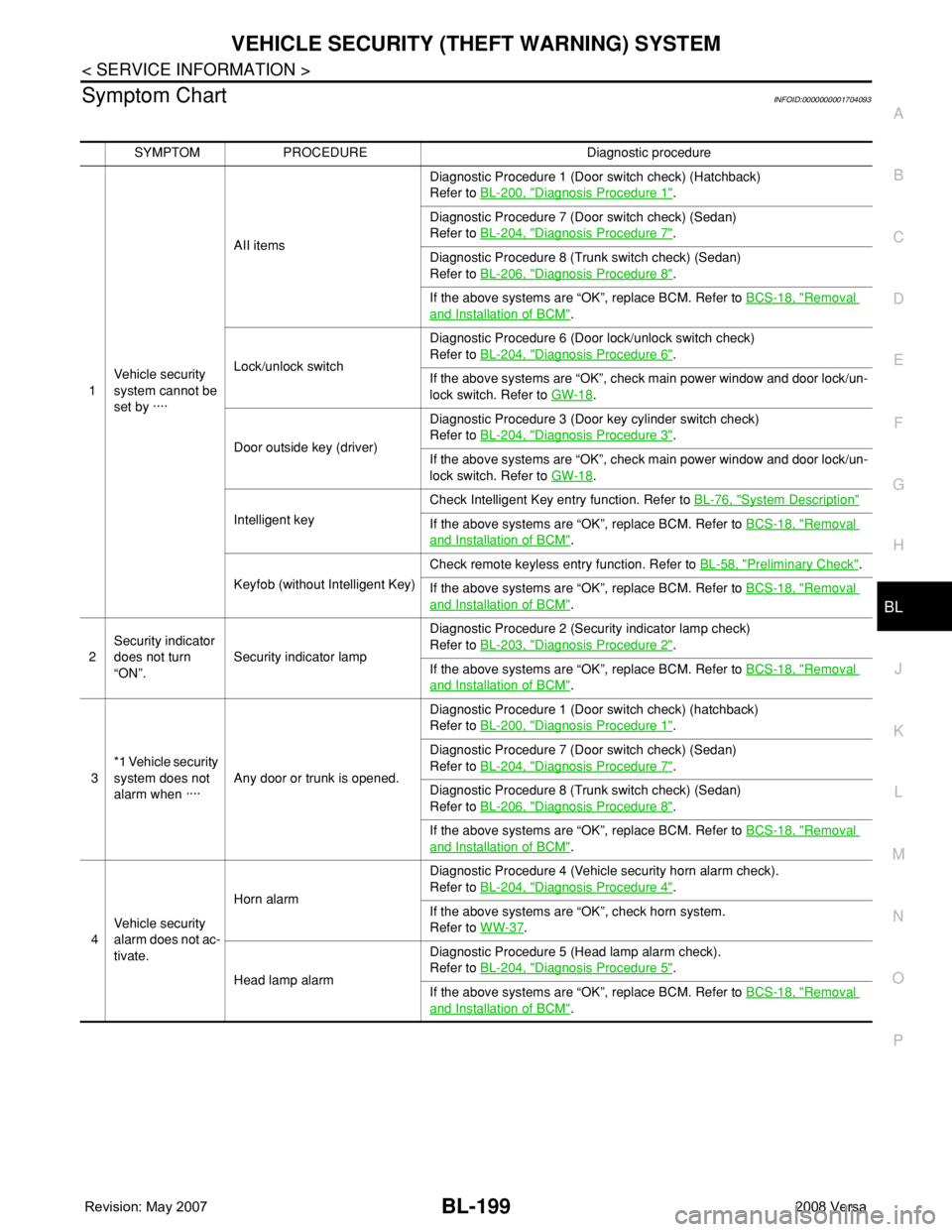
Symptom ChartINFOID:0000000001704093
SYMPTOM PROCEDURE Diagnostic procedure
1Vehicle security
system cannot be
set by ····AII itemsDiagnostic Procedure 1 (Door switch check) (Hatchback)
Refer to BL-200, "
Diagnosis Procedure 1".
Diagnostic Procedure 7 (Door switch check) (Sedan)
Refer to BL-204, "
Diagnosis Procedure 7".
Diagnostic Procedure 8 (Trunk switch check) (Sedan)
Refer to BL-206, "
Diagnosis Procedure 8".
If the above systems are “OK”, replace BCM. Refer to BCS-18, "
Removal
and Installation of BCM".
Lock/unlock switchDiagnostic Procedure 6 (Door lock/unlock switch check)
Refer to BL-204, "
Diagnosis Procedure 6".
If the above systems are “OK”, check main power window and door lock/un-
lock switch. Refer to GW-18
.
Door outside key (driver)Diagnostic Procedure 3 (Door key cylinder switch check)
Refer to BL-204, "
Diagnosis Procedure 3".
If the above systems are “OK”, check main power window and door lock/un-
lock switch. Refer to GW-18
.
Intelligent keyCheck Intelligent Key entry function. Refer to BL-76, "
System Description"
If the above systems are “OK”, replace BCM. Refer to BCS-18, "Removal
and Installation of BCM".
Keyfob (without Intelligent Key)Check remote keyless entry function. Refer to BL-58, "
Preliminary Check".
If the above systems are “OK”, replace BCM. Refer to BCS-18, "
Removal
and Installation of BCM".
2Security indicator
does not turn
“ON”.Security indicator lampDiagnostic Procedure 2 (Security indicator lamp check)
Refer to BL-203, "
Diagnosis Procedure 2".
If the above systems are “OK”, replace BCM. Refer to BCS-18, "
Removal
and Installation of BCM".
3*1 Vehicle security
system does not
alarm when ····Any door or trunk is opened.Diagnostic Procedure 1 (Door switch check) (hatchback)
Refer to BL-200, "
Diagnosis Procedure 1".
Diagnostic Procedure 7 (Door switch check) (Sedan)
Refer to BL-204, "
Diagnosis Procedure 7".
Diagnostic Procedure 8 (Trunk switch check) (Sedan)
Refer to BL-206, "
Diagnosis Procedure 8".
If the above systems are “OK”, replace BCM. Refer to BCS-18, "
Removal
and Installation of BCM".
4Vehicle security
alarm does not ac-
tivate.Horn alarmDiagnostic Procedure 4 (Vehicle security horn alarm check).
Refer to BL-204, "
Diagnosis Procedure 4".
If the above systems are “OK”, check horn system.
Refer to WW-37
.
Head lamp alarmDiagnostic Procedure 5 (Head lamp alarm check).
Refer to BL-204, "
Diagnosis Procedure 5".
If the above systems are “OK”, replace BCM. Refer to BCS-18, "
Removal
and Installation of BCM".
Page 638 of 2771
BL-204
< SERVICE INFORMATION >
VEHICLE SECURITY (THEFT WARNING) SYSTEM
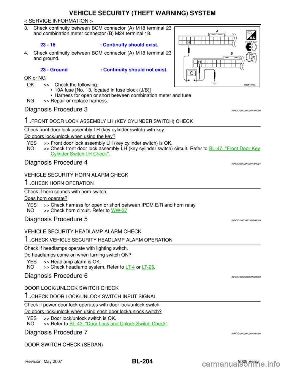
3. Check continuity between BCM connector (A) M18 terminal 23
and combination meter connector (B) M24 terminal 18.
4. Check continuity between BCM connector (A) M18 terminal 23
and ground.
OK or NG
OK >> Check the following:
• 10A fuse [No. 13, located in fuse block (J/B)]
• Harness for open or short between combination meter and fuse
NG >> Repair or replace harness.
Diagnosis Procedure 3INFOID:0000000001704096
1.FRONT DOOR LOCK ASSEMBLY LH (KEY CYLINDER SWITCH) CHECK
Check front door lock assembly LH (key cylinder switch) with key.
Do doors lock/unlock when using the key?
YES >> Front door lock assembly LH (key cylinder switch) is OK.
NO >> Check front door lock assembly LH (key cylinder switch) circuit. Refer to BL-47, "
Front Door Key
Cylinder Switch LH Check".
Diagnosis Procedure 4INFOID:0000000001704097
VEHICLE SECURITY HORN ALARM CHECK
1.CHECK HORN OPERATION
Check if horn sounds with horn switch.
Does horn operate?
YES >> Check harness for open or short between IPDM E/R and horn relay.
NO >> Check horn circuit. Refer to WW-37
.
Diagnosis Procedure 5INFOID:0000000001704098
VEHICLE SECURITY HEADLAMP ALARM CHECK
1.CHECK VEHICLE SECURITY HEADLAMP ALARM OPERATION
Check if headlamps operate with lighting switch.
Do headlamps come on when turning switch ON?
YES >> Headlamp alarm is OK.
NO >> Check headlamp system. Refer to LT- 4
or LT- 2 5.
Diagnosis Procedure 6INFOID:0000000001704099
DOOR LOCK/UNLOCK SWITCH CHECK
1.CHECK DOOR LOCK/UNLOCK SWITCH INPUT SIGNAL
Check if power door lock operates with door lock/unlock switch.
Do doors lock/unlock when using each door lock/unlock switch?
YES >> Door lock/unlock switch is OK.
NO >> Refer to BL-42, "
Door Lock and Unlock Switch Check".
Diagnosis Procedure 7INFOID:0000000001704100
DOOR SWITCH CHECK (SEDAN)
23 - 18 : Continuity should exist.
23 - Ground : Continuity should not exist.
WIIA1269E
Page 822 of 2771

OVERHEATING CAUSE ANALYSIS
CO-5
< SERVICE INFORMATION >
C
D
E
F
G
H
I
J
K
L
MA
CO
N
P O
OVERHEATING CAUSE ANALYSIS
Troubleshooting ChartINFOID:0000000001702527
Symptom Check items
Cooling sys-
tem parts
malfunctionPoor heat transferWater pump malfunction Worn or loose drive belt
— Thermostat stuck closed Thermostat
Damaged finsDust contamination or pa-
per clogging
Physical damage
Clogged radiator cooling
tubeExcess foreign material
(rust, dirt, sand, etc.)
Reduced air flowCooling fan does not oper-
ate
Fan assembly— High resistance to fan rota-
tion
Damaged fan blades
Damaged radiator shroud — —
Improper engine coolant
mixture ratio—
—
Engine coolant viscosity—
Poor engine coolant quality — —
Insufficient engine coolantEngine coolant leaksCooling hoseLoose clamp
Cracked hose
Water pump Poor sealing
Radiator capLoose
Poor sealing
RadiatorO-ring for damage, deterio-
ration or improper fitting
Cracked radiator tank
Cracked radiator core
Reservoir tank Cracked reservoir tank
Overflowing reservoir tankExhaust gas leaks into cool-
ing systemCylinder head deterioration
Cylinder head gasket deteri-
oration