2008 NISSAN TIIDA Lighting System
[x] Cancel search: Lighting SystemPage 1 of 2771

-1
QUICK REFERENCE INDEX
AGENERAL INFORMATIONGIGeneral Information
BENGINEEMEngine Mechanical
LUEngine Lubrication System
COEngine Cooling System
ECEngine Control System
FLFuel System
EXExhaust System
ACCAccelerator Control System
CTRANSMISSION/
TRANSAXLECLClutch System
MTManual Transaxle
ATAutomatic Transaxle
CVTCVT
DDRIVELINE/AXLEFAXFront Axle
RAXRear Axle
ESUSPENSIONFSUFront Suspension
RSURear Suspension
WTRoad Wheels & Tires
FBRAKESBRBrake System
PBParking Brake System
BRCBrake Control System
GSTEERINGPSPower Steering System
STCSteering Control System
HRESTRAINTSSBSeat Belts
SRSSupplemental Restraint System (SRS)
IBODYBLBody, Lock & Security System
GWGlasses, Window System & Mirrors
RFRoof
EIExterior & Interior
IPInstrument Panel
SESeat
JAIR CONDITIONERMTCManual Air Conditioner
KELECTRICALSCStarting & Charging System
LTLighting System
DIDriver Information System
WWWiper, Washer & Horn
BCSBody Control System
LANLAN System
AVAudio Visual, Navigation & Telephone System
ACSAuto Cruise Control System
PGPower Supply, Ground & Circuit Elements
LMAINTENANCEMAMaintenance
Edition: May 2007
Revision: May 2007
Publication No. SM8E-1C11U0
B
D
© 2007 NISSAN NORTH AMERICA, INC.
All rights reserved. No part of this Service Manual may be reproduced or stored in a retrieval system, or transmitted in any
form, or by any means, electronic, mechanical, photo-copying, recording or otherwise, without the prior written permission
of Nissan North America Inc.
A
C
E
F
G
H
I
J
K
L
M
Page 381 of 2771
AV-22
< SERVICE INFORMATION >
AUDIO
Power Supply Circuit Inspection
INFOID:0000000001704663
1.CHECK FUSE
Check that the following fuses of the subwoofer (premium system) and audio unit are not blown.
OK or NG
OK >> GO TO 2.
NG >> If fuse is blown, be sure to eliminate cause of blown fuse before installing new fuse. Refer to PG-
3 .
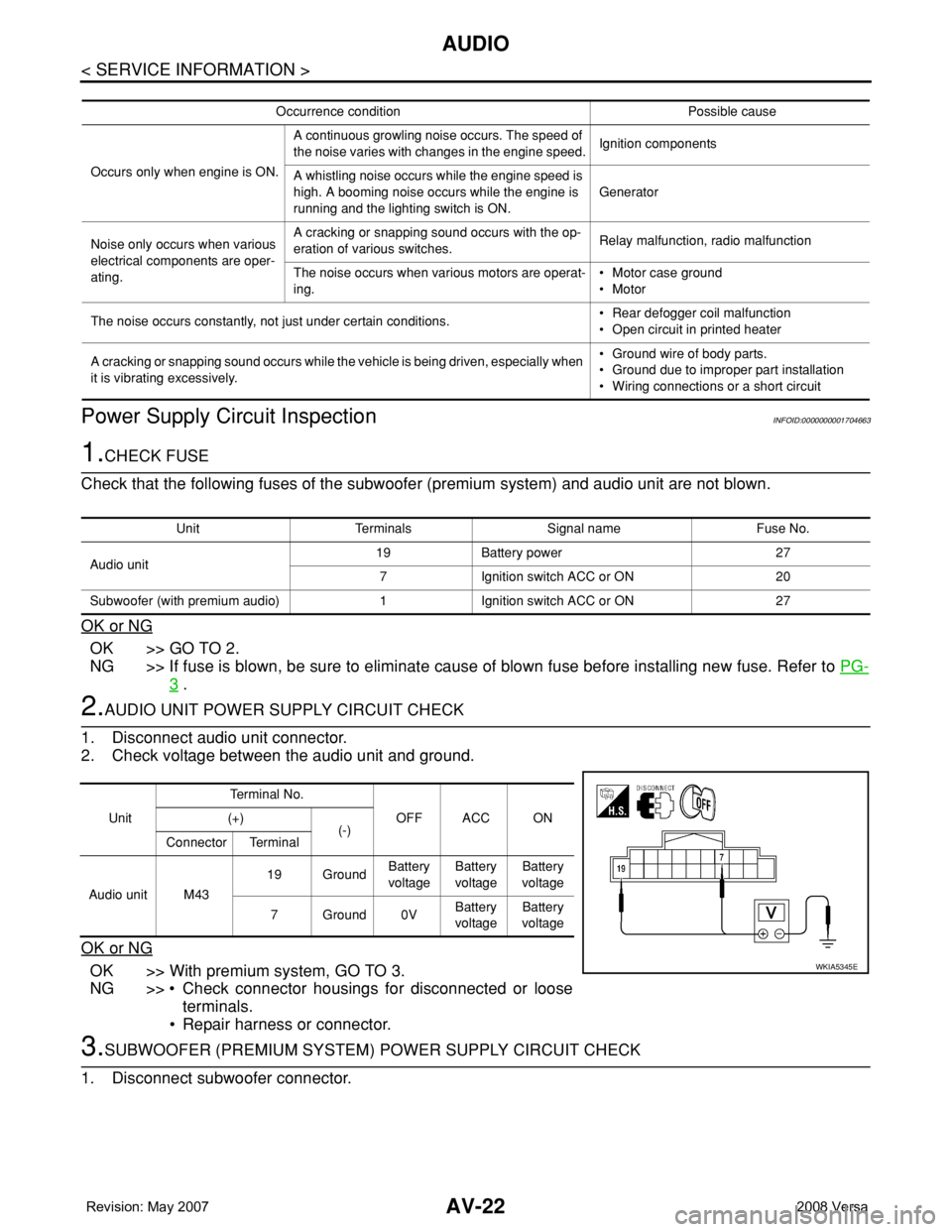
2.AUDIO UNIT POWER SUPPLY CIRCUIT CHECK
1. Disconnect audio unit connector.
2. Check voltage between the audio unit and ground.
OK or NG
OK >> With premium system, GO TO 3.
NG >> • Check connector housings for disconnected or loose
terminals.
• Repair harness or connector.
3.SUBWOOFER (PREMIUM SYSTEM) POWER SUPPLY CIRCUIT CHECK
1. Disconnect subwoofer connector.
Occurrence condition Possible cause
Occurs only when engine is ON.A continuous growling noise occurs. The speed of
the noise varies with changes in the engine speed.Ignition components
A whistling noise occurs while the engine speed is
high. A booming noise occurs while the engine is
running and the lighting switch is ON.Generator
Noise only occurs when various
electrical components are oper-
ating.A cracking or snapping sound occurs with the op-
eration of various switches.Relay malfunction, radio malfunction
The noise occurs when various motors are operat-
ing.• Motor case ground
• Motor
The noise occurs constantly, not just under certain conditions.• Rear defogger coil malfunction
• Open circuit in printed heater
A cracking or snapping sound occurs while the vehicle is being driven, especially when
it is vibrating excessively.• Ground wire of body parts.
• Ground due to improper part installation
• Wiring connections or a short circuit
Unit Terminals Signal name Fuse No.
Audio unit19 Battery power 27
7 Ignition switch ACC or ON 20
Subwoofer (with premium audio) 1 Ignition switch ACC or ON 27
UnitTe r m i n a l N o .
OFF ACC ON (+)
(-)
Connector Terminal
Audio unit M4319 GroundBattery
voltageBattery
voltageBattery
voltage
7Ground0VBattery
voltageBattery
voltage
WKIA5345E
Page 420 of 2771
BCS-4
< SERVICE INFORMATION >
BCM (BODY CONTROL MODULE)
NOTE:
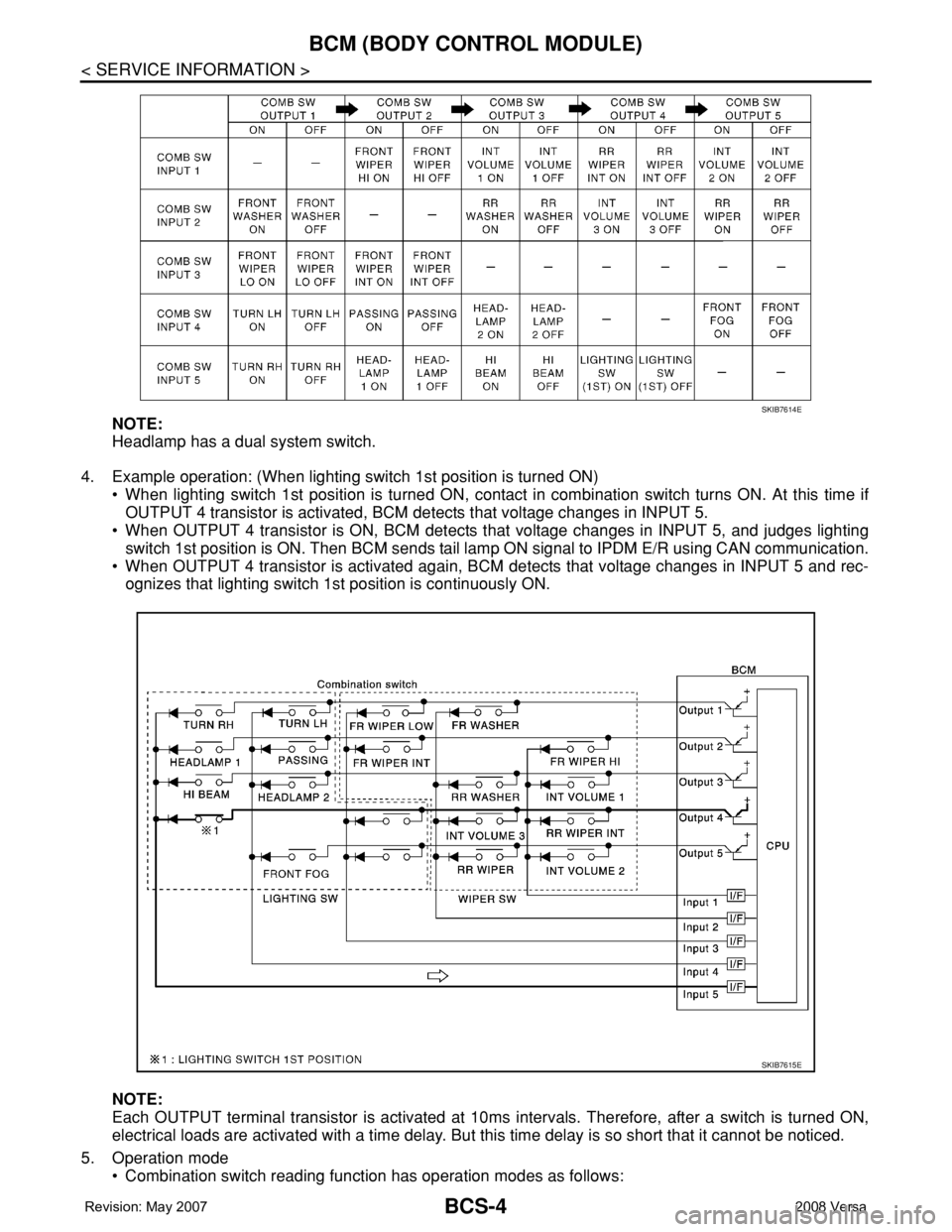
Headlamp has a dual system switch.
4. Example operation: (When lighting switch 1st position is turned ON)
• When lighting switch 1st position is turned ON, contact in combination switch turns ON. At this time if
OUTPUT 4 transistor is activated, BCM detects that voltage changes in INPUT 5.
• When OUTPUT 4 transistor is ON, BCM detects that voltage changes in INPUT 5, and judges lighting
switch 1st position is ON. Then BCM sends tail lamp ON signal to IPDM E/R using CAN communication.
• When OUTPUT 4 transistor is activated again, BCM detects that voltage changes in INPUT 5 and rec-
ognizes that lighting switch 1st position is continuously ON.
NOTE:
Each OUTPUT terminal transistor is activated at 10ms intervals. Therefore, after a switch is turned ON,
electrical loads are activated with a time delay. But this time delay is so short that it cannot be noticed.
5. Operation mode
• Combination switch reading function has operation modes as follows:
SKIB7614E
SKIB7615E
Page 421 of 2771
BCM (BODY CONTROL MODULE)
BCS-5
< SERVICE INFORMATION >
C
D
E
F
G
H
I
J
L
MA
B
BCS
N
O
P
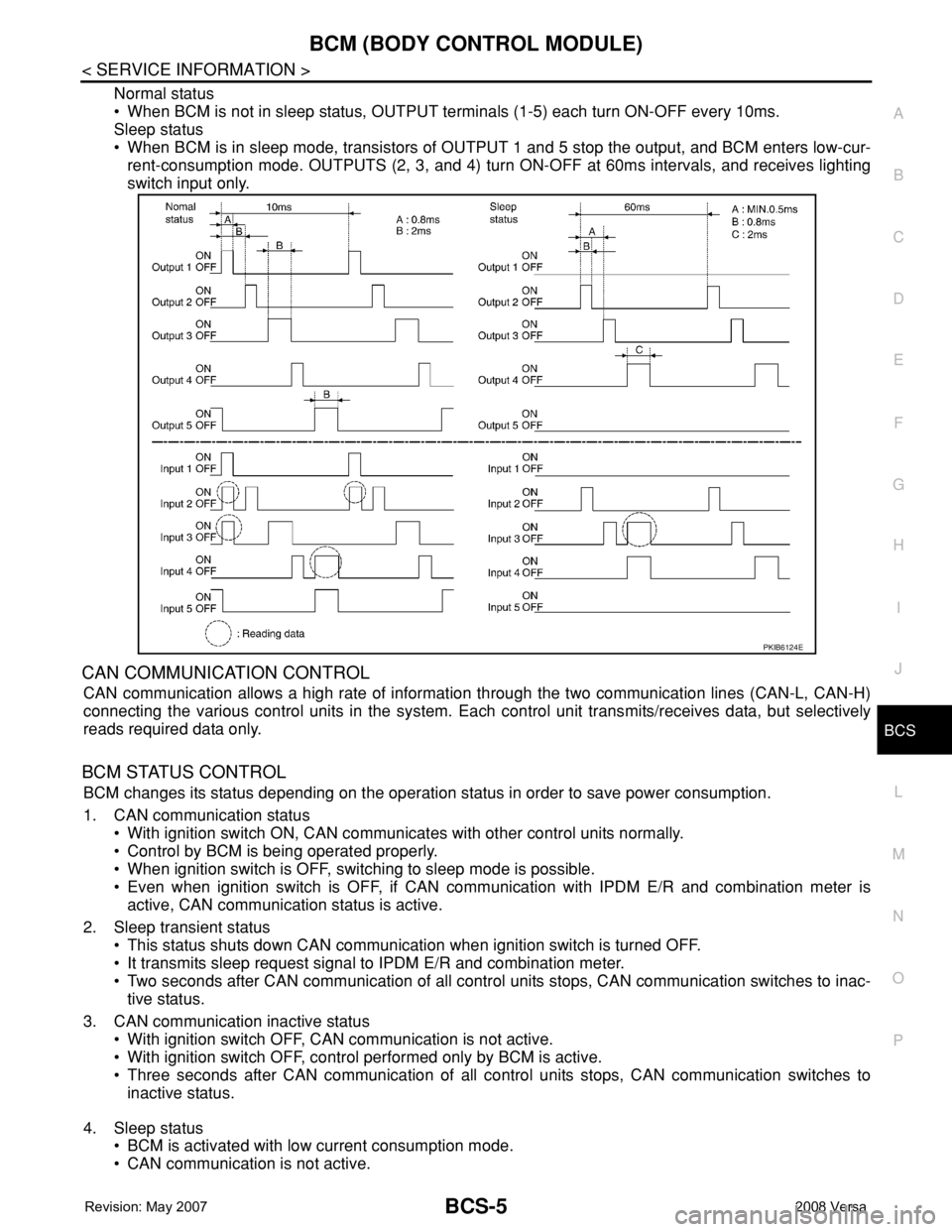
Normal status
• When BCM is not in sleep status, OUTPUT terminals (1-5) each turn ON-OFF every 10ms.
Sleep status
• When BCM is in sleep mode, transistors of OUTPUT 1 and 5 stop the output, and BCM enters low-cur-
rent-consumption mode. OUTPUTS (2, 3, and 4) turn ON-OFF at 60ms intervals, and receives lighting
switch input only.
CAN COMMUNICATION CONTROL
CAN communication allows a high rate of information through the two communication lines (CAN-L, CAN-H)
connecting the various control units in the system. Each control unit transmits/receives data, but selectively
reads required data only.
BCM STATUS CONTROL
BCM changes its status depending on the operation status in order to save power consumption.
1. CAN communication status
• With ignition switch ON, CAN communicates with other control units normally.
• Control by BCM is being operated properly.
• When ignition switch is OFF, switching to sleep mode is possible.
• Even when ignition switch is OFF, if CAN communication with IPDM E/R and combination meter is
active, CAN communication status is active.
2. Sleep transient status
• This status shuts down CAN communication when ignition switch is turned OFF.
• It transmits sleep request signal to IPDM E/R and combination meter.
• Two seconds after CAN communication of all control units stops, CAN communication switches to inac-
tive status.
3. CAN communication inactive status
• With ignition switch OFF, CAN communication is not active.
• With ignition switch OFF, control performed only by BCM is active.
• Three seconds after CAN communication of all control units stops, CAN communication switches to
inactive status.
4. Sleep status
• BCM is activated with low current consumption mode.
• CAN communication is not active.
PKIB6124E
Page 422 of 2771
BCS-6
< SERVICE INFORMATION >
BCM (BODY CONTROL MODULE)
• When CAN communication operation is detected, it switches to CAN communication status.
• When a state of the following switches changes, it switches to CAN communication state:
- Ignition switch
- Key switch (without Intelligent Key)
- Key switch and ignition knob switch (with Intelligent Key)
- Hazard switch
- Door lock/unlock switch
- Front door switch (LH, RH)
- Rear door switch (LH, RH)
- Back door lock assembly (Hatchback)
- Trunk key cylinder switch (Sedan)
- Trunk lamp switch and trunk release solenoid (Sedan)
- Combination switch (passing, lighting switch 1st position, front fog lamp)
- Keyfob (lock/unlock signal)
- Front door key cylinder switch LH
• When control performed only by BCM is required by switch, it shifts to CAN communication inactive
mode.
• Status of combination switch reading function is changed.
SYSTEMS CONTROLLED BY BCM DIRECTLY
• Power door lock system. Refer to BL-22 .
• Remote keyless entry system. Refer to BL-51
.
• Power window system. Refer to GW-18
. NOTE
• Sunroof system. Refer to RF-10. NOTE
• Room lamp timer. Refer to LT- 8 9 .
• Rear wiper and washer system. Refer to WW-24
.
NOTE:
Power supply only. No system control.
SYSTEMS CONTROLLED BY BCM AND IPDM E/R
• Panic system. Refer to BL-51 .
• Vehicle security (theft warning) system. Refer to BL-187
.
• NVIS(NATS) system. Refer to BL-210
.
• Headlamp, tail lamp and battery saver control systems. Refer to LT- 7 2
, LT- 4 or LT- 2 5 .
• Front fog lamp. Refer to LT- 3 9
.
• Front wiper and washer system. Refer to WW-3
.
• Rear window defogger system. Refer to GW-49
.
SYSTEMS CONTROLLED BY BCM AND COMBINATION METER
• Warning chime. Refer to DI-41 .
• Turn signal and hazard warning lamps. Refer to LT- 4 8
.
SYSTEMS CONTROLLED BY BCM AND INTELLIGENT KEY UNIT
• Intelligent Key system. Refer to BL-74 .
MAJOR COMPONENTS AND CONTROL SYSTEM
System Input Output
Remote keyless entry systemRemote keyless entry receiver
(keyfob)• All door locking actuators
• Turn signal lamp (LH, RH)
• Combination meter (turn signal lamp)
Intelligent Key system Intelligent Key unit• All door locking actuators
• Turn signal lamp (LH, RH)
• Combination meter (turn signal lamp)
Power door lock systemFront power door lock/unlock
switch (LH, RH)All door locking actuators
Power supply (IGN/RAP) to power
windowIgnition retained power supply Power supply to power window and sunroof system
Power supply (BAT) to power window Battery power supply Power supply to power window and sunroof system
Page 575 of 2771
INTELLIGENT KEY SYSTEM
BL-141
< SERVICE INFORMATION >
C
D
E
F
G
H
J
K
L
MA
B
BL
N
O
P
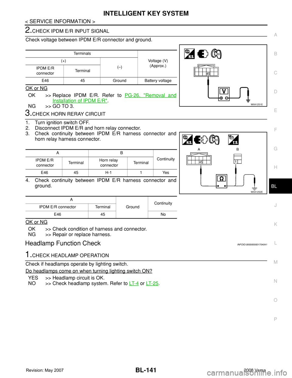
2.CHECK IPDM E/R INPUT SIGNAL
Check voltage between IPDM E/R connector and ground.
OK or NG
OK >> Replace IPDM E/R. Refer to PG-26, "Removal and
Installation of IPDM E/R".
NG >> GO TO 3.
3.CHECK HORN RERAY CIRCUIT
1. Turn ignition switch OFF.
2. Disconnect IPDM E/R and horn relay connector.
3. Check continuity between IPDM E/R harness connector and
horn relay harness connector.
4. Check continuity between IPDM E/R harness connector and
ground.
OK or NG
OK >> Check condition of harness and connector.
NG >> Repair or replace harness.
Headlamp Function CheckINFOID:0000000001704041
1.CHECK HEADLAMP OPERATION
Check if headlamps operate by lighting switch.
Do headlamps come on when turning lighting switch ON?
YES >> Headlamp circuit is OK.
NO >> Check headlamp system. Refer to LT- 4
or LT- 2 5.
Te r m i n a l s
Voltage (V)
(Approx.) (+)
(–)
IPDM E/R
connectorTe r m i n a l
E46 45 Ground Battery voltage
WIIA1251E
AB
Continuity
IPDM E/R
connectorTe r m i n a lHorn relay
connectorTe r m i n a l
E46 45 H-1 1 Yes
A
GroundContinuity
IPDM E/R connector Terminal
E46 45 No
WIIA1252E
Page 638 of 2771
BL-204
< SERVICE INFORMATION >
VEHICLE SECURITY (THEFT WARNING) SYSTEM
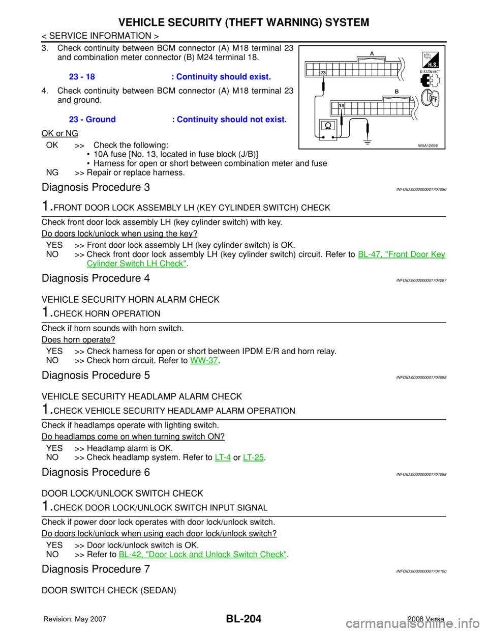
3. Check continuity between BCM connector (A) M18 terminal 23
and combination meter connector (B) M24 terminal 18.
4. Check continuity between BCM connector (A) M18 terminal 23
and ground.
OK or NG
OK >> Check the following:
• 10A fuse [No. 13, located in fuse block (J/B)]
• Harness for open or short between combination meter and fuse
NG >> Repair or replace harness.
Diagnosis Procedure 3INFOID:0000000001704096
1.FRONT DOOR LOCK ASSEMBLY LH (KEY CYLINDER SWITCH) CHECK
Check front door lock assembly LH (key cylinder switch) with key.
Do doors lock/unlock when using the key?
YES >> Front door lock assembly LH (key cylinder switch) is OK.
NO >> Check front door lock assembly LH (key cylinder switch) circuit. Refer to BL-47, "
Front Door Key
Cylinder Switch LH Check".
Diagnosis Procedure 4INFOID:0000000001704097
VEHICLE SECURITY HORN ALARM CHECK
1.CHECK HORN OPERATION
Check if horn sounds with horn switch.
Does horn operate?
YES >> Check harness for open or short between IPDM E/R and horn relay.
NO >> Check horn circuit. Refer to WW-37
.
Diagnosis Procedure 5INFOID:0000000001704098
VEHICLE SECURITY HEADLAMP ALARM CHECK
1.CHECK VEHICLE SECURITY HEADLAMP ALARM OPERATION
Check if headlamps operate with lighting switch.
Do headlamps come on when turning switch ON?
YES >> Headlamp alarm is OK.
NO >> Check headlamp system. Refer to LT- 4
or LT- 2 5.
Diagnosis Procedure 6INFOID:0000000001704099
DOOR LOCK/UNLOCK SWITCH CHECK
1.CHECK DOOR LOCK/UNLOCK SWITCH INPUT SIGNAL
Check if power door lock operates with door lock/unlock switch.
Do doors lock/unlock when using each door lock/unlock switch?
YES >> Door lock/unlock switch is OK.
NO >> Refer to BL-42, "
Door Lock and Unlock Switch Check".
Diagnosis Procedure 7INFOID:0000000001704100
DOOR SWITCH CHECK (SEDAN)
23 - 18 : Continuity should exist.
23 - Ground : Continuity should not exist.
WIIA1269E
Page 652 of 2771
BL-218
< SERVICE INFORMATION >
NATS (NISSAN ANTI-THEFT SYSTEM)
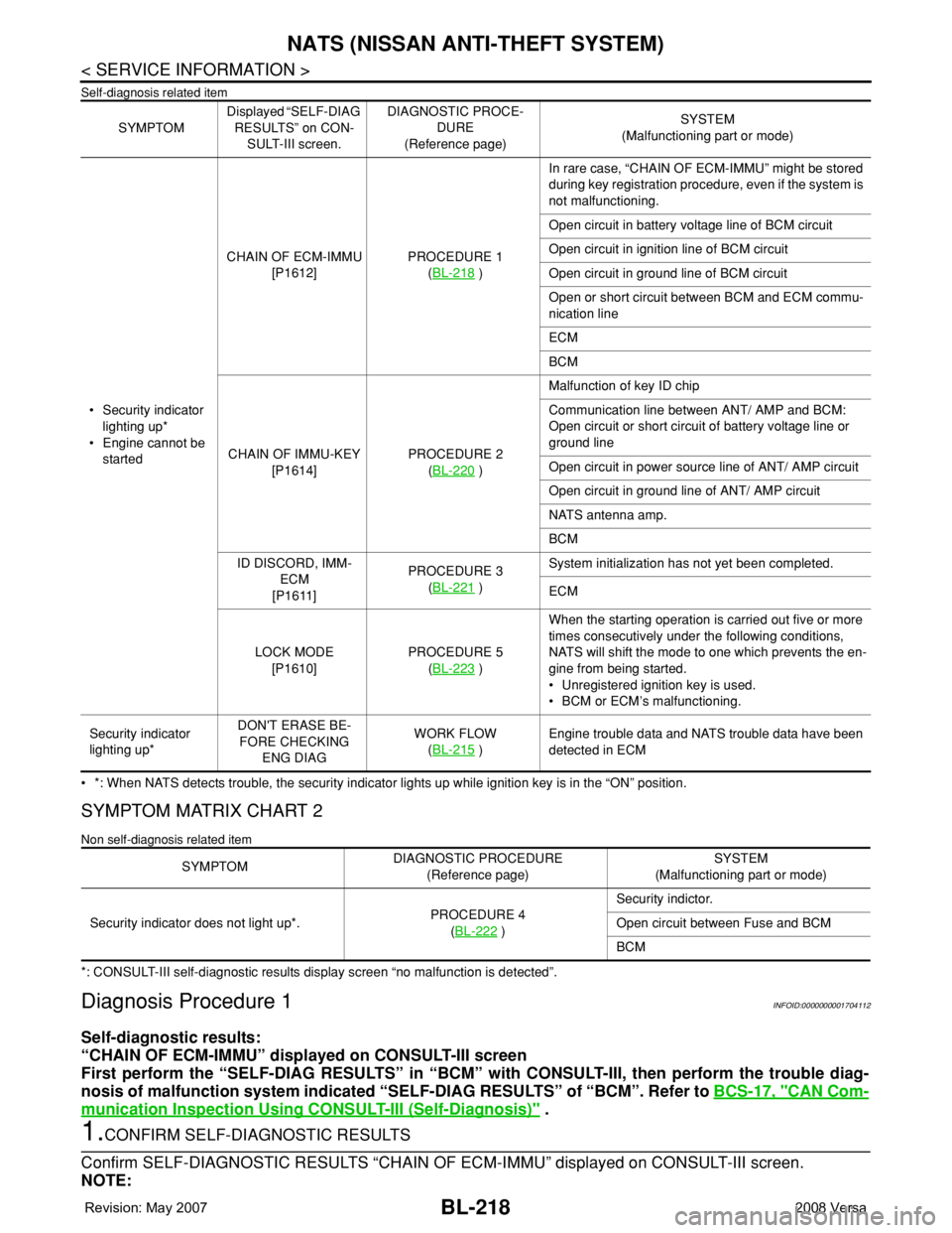
Self-diagnosis related item
• *: When NATS detects trouble, the security indicator lights up while ignition key is in the “ON” position.
SYMPTOM MATRIX CHART 2
Non self-diagnosis related item
*: CONSULT-III self-diagnostic results display screen “no malfunction is detected”.
Diagnosis Procedure 1INFOID:0000000001704112
Self-diagnostic results:
“CHAIN OF ECM-IMMU” displayed on CONSULT-III screen
First perform the “SELF-DIAG RESULTS” in “BCM” with CONSULT-III, then perform the trouble diag-
nosis of malfunction system indicated “SELF-DIAG RESULTS” of “BCM”. Refer to BCS-17, "
CAN Com-
munication Inspection Using CONSULT-III (Self-Diagnosis)" .
1.CONFIRM SELF-DIAGNOSTIC RESULTS
Confirm SELF-DIAGNOSTIC RESULTS “CHAIN OF ECM-IMMU” displayed on CONSULT-III screen.
NOTE:
SYMPTOMDisplayed “SELF-DIAG
RESULTS” on CON-
SULT-III screen.DIAGNOSTIC PROCE-
DURE
(Reference page)SYSTEM
(Malfunctioning part or mode)
• Security indicator
lighting up*
• Engine cannot be
startedCHAIN OF ECM-IMMU
[P1612]PROCEDURE 1
(BL-218
)In rare case, “CHAIN OF ECM-IMMU” might be stored
during key registration procedure, even if the system is
not malfunctioning.
Open circuit in battery voltage line of BCM circuit
Open circuit in ignition line of BCM circuit
Open circuit in ground line of BCM circuit
Open or short circuit between BCM and ECM commu-
nication line
ECM
BCM
CHAIN OF IMMU-KEY
[P1614]PROCEDURE 2
(BL-220
)Malfunction of key ID chip
Communication line between ANT/ AMP and BCM:
Open circuit or short circuit of battery voltage line or
ground line
Open circuit in power source line of ANT/ AMP circuit
Open circuit in ground line of ANT/ AMP circuit
NATS antenna amp.
BCM
ID DISCORD, IMM-
ECM
[P1611]PROCEDURE 3
(BL-221
)System initialization has not yet been completed.
ECM
LOCK MODE
[P1610]PROCEDURE 5
(BL-223
)When the starting operation is carried out five or more
times consecutively under the following conditions,
NATS will shift the mode to one which prevents the en-
gine from being started.
• Unregistered ignition key is used.
• BCM or ECM’s malfunctioning.
Security indicator
lighting up*DON'T ERASE BE-
FORE CHECKING
ENG DIAGWORK FLOW
(BL-215
)Engine trouble data and NATS trouble data have been
detected in ECM
SYMPTOMDIAGNOSTIC PROCEDURE
(Reference page)SYSTEM
(Malfunctioning part or mode)
Security indicator does not light up*.PROCEDURE 4
(BL-222
)Security indictor.
Open circuit between Fuse and BCM
BCM